EP0192193A2 - Ascenseur incliné comportant plusieurs éléments télescopiques - Google Patents
Ascenseur incliné comportant plusieurs éléments télescopiques Download PDFInfo
- Publication number
- EP0192193A2 EP0192193A2 EP86101839A EP86101839A EP0192193A2 EP 0192193 A2 EP0192193 A2 EP 0192193A2 EP 86101839 A EP86101839 A EP 86101839A EP 86101839 A EP86101839 A EP 86101839A EP 0192193 A2 EP0192193 A2 EP 0192193A2
- Authority
- EP
- European Patent Office
- Prior art keywords
- telescopic
- section
- telescopic section
- inclined elevator
- elevator according
- Prior art date
- Legal status (The legal status is an assumption and is not a legal conclusion. Google has not performed a legal analysis and makes no representation as to the accuracy of the status listed.)
- Granted
Links
Images


Classifications
-
- B—PERFORMING OPERATIONS; TRANSPORTING
- B65—CONVEYING; PACKING; STORING; HANDLING THIN OR FILAMENTARY MATERIAL
- B65G—TRANSPORT OR STORAGE DEVICES, e.g. CONVEYORS FOR LOADING OR TIPPING, SHOP CONVEYOR SYSTEMS OR PNEUMATIC TUBE CONVEYORS
- B65G21/00—Supporting or protective framework or housings for endless load-carriers or traction elements of belt or chain conveyors
- B65G21/10—Supporting or protective framework or housings for endless load-carriers or traction elements of belt or chain conveyors movable, or having interchangeable or relatively movable parts; Devices for moving framework or parts thereof
- B65G21/14—Supporting or protective framework or housings for endless load-carriers or traction elements of belt or chain conveyors movable, or having interchangeable or relatively movable parts; Devices for moving framework or parts thereof to allow adjustment of length or configuration of load-carrier or traction element
-
- B—PERFORMING OPERATIONS; TRANSPORTING
- B66—HOISTING; LIFTING; HAULING
- B66B—ELEVATORS; ESCALATORS OR MOVING WALKWAYS
- B66B9/00—Kinds or types of lifts in, or associated with, buildings or other structures
- B66B9/16—Mobile or transportable lifts specially adapted to be shifted from one part of a building or other structure to another part or to another building or structure
Definitions
- the invention relates to an inclined elevator consisting of a plurality of telescopic sections, the individual telescopic sections having guide rails for a load platform or the like which can be moved thereon, at least one telescopic section being cable-operated by means of a cable-operated, automatically snapping locking device which can be bent via a joint, and the kinked section of the telescopic section Guidance of another telescopic shot is used.
- Such inclined elevators consist of a plurality of telescopic sections and which are generally used in the construction industry for the transport of loads from the ground level to the roof area.
- Such inclined lifts are used for loading Move roof tiles with suitable load platforms, pouring buckets or the like.
- the upper, last telescopic section can be swiveled into different angular positions with the aid of a cable deflection device and can be fixed in these angular positions, the load platform or the like being able to pass over the kink area.
- both the upper end of the second-last telescopic section and the lower end of the last telescopic section are provided with a joint, that is to say they can be bent. It is necessary to move the kinks of both telescopic sections exactly one above the other so that they can be kinked.
- Such inclined lifts have proven themselves.
- a disadvantage of the known inclined elevators was that two kink points had to be moved exactly one above the other. Furthermore, part of the useful length of the last telescopic section was lost due to the lower, bent part of the last telescopic section remaining in the second last telescopic section. Secondly, it was necessary to guide the two telescopic sections into each other both to initiate the bending process and during the bending process on both sides of the articulated joint. In the event of severe angulation, the forces introduced into the joint are transmitted so that the parts that are brought together deform. This in turn has a disadvantageous effect on driving over the load platform or the like. In individual cases, the load platform may no longer drive over the deformed kink can. It was therefore necessary to carefully maintain the previously known inclined elevator in the area of its kink.
- the object of the invention is to eliminate the disadvantages described above, i.e. To reduce the susceptibility to wear in the area of the kink, to increase the useful length of the last telescopic section and to increase the safety when driving over the load platform.
- the invention solves this problem in an inclined elevator of the type mentioned in that the further (i.e. last) telescopic section has no articulated joint, is guided with respect to the bent telescopic section in the bent position only in the bent section of the same and is locked in this section.
- the invention thus frees itself from the consideration that it is necessary to provide the last telescopic section with an articulated joint. Rather, only the penultimate telescopic shot is kinked.
- This has the advantage that the last telescopic section can be moved with its free end beyond the kink as an "inherently stiff" telescopic section and can only be angled after the kink has been passed. So there are no constraints during the run-over because the articulated joint in the second to last telescopic section is in an absolutely extended position and the last telescope shot has no kinks that make the leadership indefinable.
- Simplification of the joint is also important; Since it is no longer necessary to cover two joint axes (namely the joint axes of both telescopic sections), no constraints are introduced into the joint.
- the locking of the two telescopic sections to one another is no longer located, as in the known embodiment, outside the kink area in the "straight" part of the second to last telescopic section, but was instead placed according to the invention in the bent section of the second to last telescopic section.
- the two telescopic sections can be locked together reliably and reliably.
- the articulated joint is formed by a hinge joint bridging the guide rail track and is wider than the guide rail track. The widening is directed outwards so that the inner sides are flush and the rollers of the load platform or the like guide safely.
- the hinge joint is advantageously designed so that it is arranged above the guide rail track and has hinge tabs which are formed with their free ends tapering to the level of the guide rail track. In this way, a smooth transition of the top rollers of the load platform or the like from the actual guide rail track to the hinge joint is possible.
- this section has a cross member on which a part of the locking device is arranged.
- This cross-member - and thus the part of the locking device - thus located at the extreme end of the penultimate telescope runner, which means a maximum utilization of the Nutzlän g s of the guide rail.
- the cross member itself is designed in such a way that it is double-plate over parts of its width and between the plates a spring-loaded lever carrying the locking bolt is guided.
- guide rollers for the load rope are arranged on the cross member A.
- the second part of the lock is located on the further (last) telescopic section. It is formed in that this telescopic section has a cross belt at the end, which has a locking latch which forms the counter-locking.
- extension limiters are arranged.
- the invention proposes an inclined elevator of the type mentioned at the outset, the kinking being effected by means of a rail rope guided in a pulley-like manner over several rollers, and the rollers being mounted in a cross member which engages under the further telescopic section and which is guided by sliding shoes on the further telescopic section , before that the cross member has two rollers offset in the longitudinal direction of the telescopic section, the axes of which are inclined to one another. Due to the inclination of the axes, the rail cable running from one of these two rollers can run back without constraints to the cross member forming the end of the bent penultimate telescopic shot and be fastened there.
- the kinking being effected by means of a rail rope which is guided in a pulley-like manner over several rollers, and the rollers are mounted in a cross member which engages under the lower telescopic section and which is guided by sliding shoes on the further telescopic section and wherein the guide shoes are connected via telescope tubes to the non-bent portion of the telescopic section, further suggested that the T eleskoprohre have an adjustable end stop.
- This technical teaching enables exact adjustment of the effective entry length the telescopic tubes, so that the stretched position of the second to last telescopic shot (straight joint) can be precisely defined, which results in a perfect guidance of the last telescopic shot.
- the end of the telescopic tubes is fork-like on the one hand on a support bracket arranged on the non-kinked section of the bendable telescopic section, on the other hand fork-like on the guide shoe and a spacing screw is provided as an adjustable end stop.
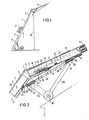
- the inclined elevator 1 consists of several telescopic sections a - e, on which a load platform 3 is guided in the illustrated embodiment. With 49 the side wall of a building is designated. A hinge joint 4 is provided between the telescopic sections a and b.
- the hinge joint consists of two hinge tabs 5, which the guide rail 2 and the guide rail 2 ' connect each other. As can be seen in particular from FIG. 2, the hinge flaps 5 run out in the region of the guide rail raceways 7, so that the load platform 3 enables a bump-free passage.
- the kink (see item 47 in Fig. 2) is not connected by a hinge;
- the invention is not left if a hinge is provided here, which is slidably arranged below the lower flange of the guide rail 2 in such a way that it can be included as a load-bearing joint in the kink area.
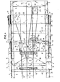
- a cross member 8 is provided at the extreme end of the bent section 6, which consists of two plates 10 and 11 arranged at a distance from one another. Between these two plates 10 and 11, a part 9 of the locking device is arranged, which essentially consists of the lever 14 with the locking bolt 13 and the associated spring 12.
- a cross belt 18 (FIGS. 5 and 6) is arranged, which carries the counter lock 19.
- the counter-lock 19 consists essentially of the bolt latch 20 with the leaf spring 20 'and the locking piece 41. It can be seen that with the locking fully engaged (FIGS. 2 and 4) the bolt bolt 13 has bypassed the bolt latch 20 and in the recess of this bolt latch snaps into place. The bolt only releases when the further (last) telescopic shot is extended again drop the locking bolt so that it can move around to the left in the image plane (due to the load on the spring 12, see arrow direction 50 in FIG. 6) and can bypass the locking latch.
- extension limiters designated with 21 and 22 are provided, the extension limiter 22 being arranged on a cross member of the last telescopic section and the extension limiter 21 on the cross member 8.
- the rope referred to as rail rope 37 (which both extends and retracts the telescopic sections and also causes the kink) is first guided over the roller 24 from the winch (not shown).
- the roller 24 is arranged in a cross member 26 designed as a roller box. From here, the rail cable is guided further over the roller designated 23, which is displaced in the roller box 39, which in turn is mounted on the non-kinked (straight) section 29 of the second-last telescopic section via a pivot axis 38. From here, the rail cable runs further to the roller 25 and from there to the attachment on the cross member 8, which is designated by 40.
- the roller 25 is mounted in a special roller box 48 (FIG.
- rollers 24 and 25 are thus offset in the longitudinal direction of the telescopic shot.
- the special displacement of the roller 25 and by an inclination of the roller box 48 with respect to the vertical ensures that the rail cable 37 runs somewhat obliquely onto the roller 25, so that a better one Course to the attachment point 40 is given.
- the axes 31 and 32 of the rollers 24 and 25 are thus slightly inclined towards each other.
- the cross member 26 has in a known manner guide shoes 27 with which it slidably engages over the guide rails 2 'of the telescopic section a.
- the load cable 17 is guided at the very end of the last telescopic section a over a roller 44, with deflector rollers 15, 15 ', 16 and 16' serving to guide the load cable as well as the deflector roller 42 is used to guide the rail cable.
- support beams 35 are provided on the bent telescopic section, which are connected to the latter at an angle-resistant manner.
- a link 36 is connected to this support bracket via a pivot axis 46, which is in turn connected to the slide shoe 27 by means of a pivot axis 45.
- the fork 34 of an outer telescopic tube which is generally designated 28, is also attached to the slide shoe 27.
- the inner telescopic tube engages with a further fork 33 on a pivot axis 38, which at the same time carries the roller box 39.
- an adjustable end stop, designated 30, is provided, with the aid of which the effective length of the telescopic tube can be exactly determined.
- the fork 34 is pivotally mounted on the slide shoe 27 as well as on the handlebar 36 via the pivot axis 45.
- stiffening belts which have been designated 43.
Landscapes
- Engineering & Computer Science (AREA)
- Structural Engineering (AREA)
- Civil Engineering (AREA)
- Transportation (AREA)
- Automation & Control Theory (AREA)
- Mechanical Engineering (AREA)
- Types And Forms Of Lifts (AREA)
- Lift-Guide Devices, And Elevator Ropes And Cables (AREA)
- Ladders (AREA)
- Actuator (AREA)
- Vehicle Cleaning, Maintenance, Repair, Refitting, And Outriggers (AREA)
- Valve-Gear Or Valve Arrangements (AREA)
Priority Applications (1)
| Application Number | Priority Date | Filing Date | Title |
|---|---|---|---|
| AT86101839T ATE57891T1 (de) | 1985-02-16 | 1986-02-13 | Aus mehreren teleskopschuessen bestehender schraegaufzug. |
Applications Claiming Priority (2)
| Application Number | Priority Date | Filing Date | Title |
|---|---|---|---|
| DE3505506 | 1985-02-16 | ||
| DE3505506A DE3505506C2 (de) | 1985-02-16 | 1985-02-16 | Aus mehreren seilbetätigt teleskopierbaren Teleskopschüssen bestehender Schrägaufzug |
Publications (3)
| Publication Number | Publication Date |
|---|---|
| EP0192193A2 true EP0192193A2 (fr) | 1986-08-27 |
| EP0192193A3 EP0192193A3 (en) | 1988-08-31 |
| EP0192193B1 EP0192193B1 (fr) | 1990-10-31 |
Family
ID=6262803
Family Applications (1)
| Application Number | Title | Priority Date | Filing Date |
|---|---|---|---|
| EP86101839A Expired - Lifetime EP0192193B1 (fr) | 1985-02-16 | 1986-02-13 | Ascenseur incliné comportant plusieurs éléments télescopiques |
Country Status (3)
| Country | Link |
|---|---|
| EP (1) | EP0192193B1 (fr) |
| AT (1) | ATE57891T1 (fr) |
| DE (2) | DE3505506C2 (fr) |
Cited By (6)
| Publication number | Priority date | Publication date | Assignee | Title |
|---|---|---|---|---|
| EP0382913A1 (fr) * | 1989-02-09 | 1990-08-22 | OSTMA Maschinenbau GmbH | Dispositif de transfert, particulièrement pour machines à emballer des piles de papier |
| EP0396096A3 (fr) * | 1989-05-02 | 1991-08-14 | Albert Böcker GmbH & Co. KG | Elévateur incliné composé de plusieurs sections téléscopiques |
| EP0654427A1 (fr) * | 1993-11-18 | 1995-05-24 | ETS. THENAUD et FILS | Tapis transporteur, notamment pour camion-bétonnière |
| CN102556807A (zh) * | 2012-03-12 | 2012-07-11 | 北京建筑机械化研究院 | 具有垂直输送和倾斜输送双功能的轻便经济安全型升降机 |
| CN107352222A (zh) * | 2017-07-17 | 2017-11-17 | 何宏昌 | 一种多段式折叠输送机 |
| CN110051047A (zh) * | 2019-05-15 | 2019-07-26 | 深圳市金致远科技有限公司 | 一种防尘保护装置及带防尘保护装置的电子烟 |
Families Citing this family (1)
| Publication number | Priority date | Publication date | Assignee | Title |
|---|---|---|---|---|
| DE102004022931A1 (de) * | 2004-05-10 | 2005-12-15 | Liebherr-Mischtechnik Gmbh | Bandförderer für Fahrmischer |
Family Cites Families (4)
| Publication number | Priority date | Publication date | Assignee | Title |
|---|---|---|---|---|
| DE3120048C2 (de) * | 1981-05-20 | 1984-08-16 | Albert Boecker Gmbh & Co Kg, 4712 Werne | Teleskopausleger für Schrägaufzüge |
| US4491196A (en) * | 1981-09-23 | 1985-01-01 | Albert Bocker Gmbh & Co. Kg | Telescopic beam |
| DE3222697C2 (de) * | 1982-06-16 | 1985-06-13 | Theodor Klaas Gmbh & Co Kg, 4715 Ascheberg | Mobiler Schienenaufzug mit neigungsverstellbarer Teleskopschiene |
| DE3330082C2 (de) * | 1983-08-18 | 1986-10-23 | August Wilhelm Andernach KG, 5300 Bonn | Bausatz für einen Schrägaufzug |
-
1985
- 1985-02-16 DE DE3505506A patent/DE3505506C2/de not_active Expired
-
1986
- 1986-02-13 AT AT86101839T patent/ATE57891T1/de active
- 1986-02-13 DE DE8686101839T patent/DE3675229D1/de not_active Expired - Lifetime
- 1986-02-13 EP EP86101839A patent/EP0192193B1/fr not_active Expired - Lifetime
Cited By (7)
| Publication number | Priority date | Publication date | Assignee | Title |
|---|---|---|---|---|
| EP0382913A1 (fr) * | 1989-02-09 | 1990-08-22 | OSTMA Maschinenbau GmbH | Dispositif de transfert, particulièrement pour machines à emballer des piles de papier |
| EP0396096A3 (fr) * | 1989-05-02 | 1991-08-14 | Albert Böcker GmbH & Co. KG | Elévateur incliné composé de plusieurs sections téléscopiques |
| EP0654427A1 (fr) * | 1993-11-18 | 1995-05-24 | ETS. THENAUD et FILS | Tapis transporteur, notamment pour camion-bétonnière |
| FR2712575A1 (fr) * | 1993-11-18 | 1995-05-24 | Thenaud Fils Ets | Tapis transporteur, notamment pour camion-bétonnière. |
| CN102556807A (zh) * | 2012-03-12 | 2012-07-11 | 北京建筑机械化研究院 | 具有垂直输送和倾斜输送双功能的轻便经济安全型升降机 |
| CN107352222A (zh) * | 2017-07-17 | 2017-11-17 | 何宏昌 | 一种多段式折叠输送机 |
| CN110051047A (zh) * | 2019-05-15 | 2019-07-26 | 深圳市金致远科技有限公司 | 一种防尘保护装置及带防尘保护装置的电子烟 |
Also Published As
| Publication number | Publication date |
|---|---|
| EP0192193A3 (en) | 1988-08-31 |
| DE3675229D1 (de) | 1990-12-06 |
| ATE57891T1 (de) | 1990-11-15 |
| EP0192193B1 (fr) | 1990-10-31 |
| DE3505506C2 (de) | 1987-02-05 |
| DE3505506A1 (de) | 1986-08-28 |
Similar Documents
| Publication | Publication Date | Title |
|---|---|---|
| DE4243812C2 (de) | Schiffs-Förderanlage | |
| EP0080038A2 (fr) | Flèche télescopique, en particulier pour ascenseurs inclinés | |
| EP0192193B1 (fr) | Ascenseur incliné comportant plusieurs éléments télescopiques | |
| DE3513405C2 (fr) | ||
| EP0341563A2 (fr) | Ascenceur incliné constitué de plusieurs éléments télescopiques | |
| AT407379B (de) | Seilführung für ein windwerk, insbesondere ein hubwerk | |
| DE4023585C1 (en) | Conveyor system for goods - has laterally displaced and non-overlapping guide tracks | |
| DE3500841C1 (de) | Verriegelungsvorrichtung fuer die aneinander zwangsgefuehrten Teleskopschuesse eines Aufzuges | |
| EP0409059B1 (fr) | Système de verrouillage des éléments télescopiques d'un ascenseur incliné | |
| DE2832991C2 (de) | Kettenaufzug für zu Gruppen aneinandergekuppelte Fahrzeuge von Belustigungsvorrichtungen | |
| EP0187976B1 (fr) | Dispositif de verrouillage pour éléments télescopiques de monte-charge | |
| EP0267411B1 (fr) | Ascenseur incliné, en particulier pour personnes ou meubles | |
| DE3517291A1 (de) | Schraegaufzug fuer den transport von lasten | |
| DE3408134C2 (de) | Gerüstaufzug mit einem aus mehreren Teleskopschüssen bestehenden Teleskopausleger | |
| DE2935440A1 (de) | Antrieb fuer eine teleskoptribuene | |
| DE3322697C2 (de) | Doppelmittenkettenband für einen Kettenkratzerförderer | |
| DE2828871A1 (de) | Munitionszufuehrung fuer automatische waffen mit grossem schwenkwinkel | |
| EP0120400B1 (fr) | Assemblage entre le rail d'un monte-charge incliné et ses béquilles d'appui | |
| DE3543101C2 (de) | Verriegelungsvorrichtung für die aneinander zwangsgeführten Teleskopschüsse eines Aufzuges | |
| DE3213692A1 (de) | Stallentmistungsanlage | |
| DE602006000245T2 (de) | Luftseilförderanlage mit einem System für die seitliche Versetzung des Notseiles | |
| DE19607983C2 (de) | Lastentransportwagen für einen Schräglastenaufzug | |
| DE3532062A1 (de) | Aus mehreren teleskopschuessen bestehender schraegaufzug | |
| DE1857054U (de) | Vorrichtung zur seilfuehrung und -halterung bei einer einschienen-haengebahn. | |
| CH669590A5 (en) | Staircase conveyor for infirm person - has platform connected to front rollers each side of chain guide and rear rollers travelling on side guides |
Legal Events
| Date | Code | Title | Description |
|---|---|---|---|
| PUAI | Public reference made under article 153(3) epc to a published international application that has entered the european phase |
Free format text: ORIGINAL CODE: 0009012 |
|
| AK | Designated contracting states |
Kind code of ref document: A2 Designated state(s): AT BE CH DE FR GB IT LI LU NL SE |
|
| 17P | Request for examination filed |
Effective date: 19861223 |
|
| PUAL | Search report despatched |
Free format text: ORIGINAL CODE: 0009013 |
|
| AK | Designated contracting states |
Kind code of ref document: A3 Designated state(s): AT BE CH DE FR GB IT LI LU NL SE |
|
| 17Q | First examination report despatched |
Effective date: 19890622 |
|
| ITF | It: translation for a ep patent filed | ||
| GRAA | (expected) grant |
Free format text: ORIGINAL CODE: 0009210 |
|
| ITF | It: translation for a ep patent filed | ||
| AK | Designated contracting states |
Kind code of ref document: B1 Designated state(s): AT BE CH DE FR GB IT LI LU NL SE |
|
| REF | Corresponds to: |
Ref document number: 57891 Country of ref document: AT Date of ref document: 19901115 Kind code of ref document: T |
|
| REF | Corresponds to: |
Ref document number: 3675229 Country of ref document: DE Date of ref document: 19901206 |
|
| GBT | Gb: translation of ep patent filed (gb section 77(6)(a)/1977) | ||
| ET | Fr: translation filed | ||
| PLBE | No opposition filed within time limit |
Free format text: ORIGINAL CODE: 0009261 |
|
| STAA | Information on the status of an ep patent application or granted ep patent |
Free format text: STATUS: NO OPPOSITION FILED WITHIN TIME LIMIT |
|
| 26N | No opposition filed | ||
| ITTA | It: last paid annual fee | ||
| EPTA | Lu: last paid annual fee | ||
| EAL | Se: european patent in force in sweden |
Ref document number: 86101839.8 |
|
| PGFP | Annual fee paid to national office [announced via postgrant information from national office to epo] |
Ref country code: LU Payment date: 19961201 Year of fee payment: 12 |
|
| PGFP | Annual fee paid to national office [announced via postgrant information from national office to epo] |
Ref country code: FR Payment date: 19961230 Year of fee payment: 12 |
|
| PGFP | Annual fee paid to national office [announced via postgrant information from national office to epo] |
Ref country code: GB Payment date: 19970203 Year of fee payment: 12 |
|
| PGFP | Annual fee paid to national office [announced via postgrant information from national office to epo] |
Ref country code: DE Payment date: 19970213 Year of fee payment: 12 |
|
| PGFP | Annual fee paid to national office [announced via postgrant information from national office to epo] |
Ref country code: SE Payment date: 19970217 Year of fee payment: 12 |
|
| PGFP | Annual fee paid to national office [announced via postgrant information from national office to epo] |
Ref country code: BE Payment date: 19970219 Year of fee payment: 12 |
|
| PGFP | Annual fee paid to national office [announced via postgrant information from national office to epo] |
Ref country code: AT Payment date: 19970225 Year of fee payment: 12 |
|
| PGFP | Annual fee paid to national office [announced via postgrant information from national office to epo] |
Ref country code: NL Payment date: 19970228 Year of fee payment: 12 |
|
| PGFP | Annual fee paid to national office [announced via postgrant information from national office to epo] |
Ref country code: CH Payment date: 19970304 Year of fee payment: 12 |
|
| PG25 | Lapsed in a contracting state [announced via postgrant information from national office to epo] |
Ref country code: LU Free format text: LAPSE BECAUSE OF NON-PAYMENT OF DUE FEES Effective date: 19980213 Ref country code: GB Free format text: LAPSE BECAUSE OF NON-PAYMENT OF DUE FEES Effective date: 19980213 Ref country code: AT Free format text: LAPSE BECAUSE OF NON-PAYMENT OF DUE FEES Effective date: 19980213 |
|
| PG25 | Lapsed in a contracting state [announced via postgrant information from national office to epo] |
Ref country code: SE Free format text: LAPSE BECAUSE OF NON-PAYMENT OF DUE FEES Effective date: 19980214 |
|
| PG25 | Lapsed in a contracting state [announced via postgrant information from national office to epo] |
Ref country code: LI Free format text: LAPSE BECAUSE OF NON-PAYMENT OF DUE FEES Effective date: 19980228 Ref country code: FR Free format text: THE PATENT HAS BEEN ANNULLED BY A DECISION OF A NATIONAL AUTHORITY Effective date: 19980228 Ref country code: CH Free format text: LAPSE BECAUSE OF NON-PAYMENT OF DUE FEES Effective date: 19980228 Ref country code: BE Free format text: LAPSE BECAUSE OF NON-PAYMENT OF DUE FEES Effective date: 19980228 |
|
| BERE | Be: lapsed |
Owner name: ALBERT BOCKER G.M.B.H. & CO. K.G. Effective date: 19980228 |
|
| PG25 | Lapsed in a contracting state [announced via postgrant information from national office to epo] |
Ref country code: NL Free format text: LAPSE BECAUSE OF NON-PAYMENT OF DUE FEES Effective date: 19980901 |
|
| GBPC | Gb: european patent ceased through non-payment of renewal fee |
Effective date: 19980213 |
|
| REG | Reference to a national code |
Ref country code: CH Ref legal event code: PL |
|
| EUG | Se: european patent has lapsed |
Ref document number: 86101839.8 |
|
| NLV4 | Nl: lapsed or anulled due to non-payment of the annual fee |
Effective date: 19980901 |
|
| PG25 | Lapsed in a contracting state [announced via postgrant information from national office to epo] |
Ref country code: DE Free format text: LAPSE BECAUSE OF NON-PAYMENT OF DUE FEES Effective date: 19981103 |
|
| REG | Reference to a national code |
Ref country code: FR Ref legal event code: ST |
|
| PG25 | Lapsed in a contracting state [announced via postgrant information from national office to epo] |
Ref country code: IT Free format text: LAPSE BECAUSE OF NON-PAYMENT OF DUE FEES;WARNING: LAPSES OF ITALIAN PATENTS WITH EFFECTIVE DATE BEFORE 2007 MAY HAVE OCCURRED AT ANY TIME BEFORE 2007. THE CORRECT EFFECTIVE DATE MAY BE DIFFERENT FROM THE ONE RECORDED. Effective date: 20050213 |