EP0192278A2 - Dispositif de nettoyage des fenêtres - Google Patents
Dispositif de nettoyage des fenêtres Download PDFInfo
- Publication number
- EP0192278A2 EP0192278A2 EP86102342A EP86102342A EP0192278A2 EP 0192278 A2 EP0192278 A2 EP 0192278A2 EP 86102342 A EP86102342 A EP 86102342A EP 86102342 A EP86102342 A EP 86102342A EP 0192278 A2 EP0192278 A2 EP 0192278A2
- Authority
- EP
- European Patent Office
- Prior art keywords
- handle
- window cleaner
- cleaner according
- support bar
- receiving part
- Prior art date
- Legal status (The legal status is an assumption and is not a legal conclusion. Google has not performed a legal analysis and makes no representation as to the accuracy of the status listed.)
- Granted
Links
Images


Classifications
-
- A—HUMAN NECESSITIES
- A47—FURNITURE; DOMESTIC ARTICLES OR APPLIANCES; COFFEE MILLS; SPICE MILLS; SUCTION CLEANERS IN GENERAL
- A47L—DOMESTIC WASHING OR CLEANING; SUCTION CLEANERS IN GENERAL
- A47L1/00—Cleaning windows
- A47L1/06—Hand implements
Definitions
- the invention relates to a window cleaner with a strip-shaped carrier, a cleaner part attached to it and a stem attached at an angle to the carrier strip.
- the carrier strip usually has a groove-like profile on its front edge, into which, for example, a rubber wiping strip with a lip profile is inserted as a cleaning part. This wiper strip can be replaced when worn.
- the carrier strip often has a clamping profile in order to be able to clamp a sponge or the like, which is used primarily for moistening and pre-cleaning the panes, while the wiping strip is used for the final cleaning and the pushing off of the water from the pane surface.
- the handle usually engages at an angle on the support bar, on the one hand to maintain the necessary distance from the surface to be cleaned, and on the other hand to be able to exert the necessary pressure on the cleaning part.
- the handle of these window cleaners is usually made in several parts, a short part rigidly connected to the support bar, which is attached to the support bar at an angle, being designed as a handle in order to be able to operate the cleaning device even without a handle.
- a receiving part is mounted on a pivot axis, into which the actual handle of the cleaning device can be inserted, screwed in or fastened in some other way.
- latches are also provided in order to be able to fix the handle at different angles relative to the handle part, so that the relative position of the handle and the cleaning part can be ergonomically optimized.
- the known devices have several disadvantages. It is therefore only possible with difficulty to paint over the area in the corners of a window exactly and completely at a certain position assumed by the user with the cleaning part and thus to clean such corners perfectly. As a rule, the user has to change his position constantly. If the window pane is cleaned in vertical paths from top to bottom, the user must generally change his position here as well. In another wiping technique, in which the user pulls the window cleaner in horizontal paths over the window, he must be constantly inclined so that the water that is removed is not pushed back onto the already cleaned surface. As a rule, cleanliness along the edges of the frame suffers.
- connection between the handle part and the receiving part is to be regarded as disadvantageous, since for setting a different angular position or for dismantling the receiving part with the handle (to use the device only with the handle part) the clamping screw, which has to be tightened for a perfect fixation of both parts, has to be partially or completely loosened, which is only possible with the appropriate effort.
- the connecting parts (threaded bolt and clamping nut) dt made of metal which must either be corrosion-resistant or, in the other case, starts to rust slightly. In another known embodiment is between the handle part
- a ball joint is provided, which can be fixed in any position by means of a union nut. This allows a wide angular range to be covered, but for each change the union nut must be loosened, the desired angle set and the nut tightened again. The user makes use of this only in exceptional cases due to the associated circumstances.
- the invention has for its object to eliminate the aforementioned disadvantages.
- This object is first achieved in that the carrier bar is rotatably mounted on the handle and that the axis of rotation is approximately parallel to the plane of extent and approximately perpendicular to the direction of extension of the carrier bar or the cleaner part.
- the invention proposes a rotary connection in such a way that the support bar or the cleaner part extends around an axis running perpendicular to its longitudinal extension, the at the same time vertically or - depending on the position of the cleaning device - at a more or less inclined angle to the disc surface to be cleaned, automatically or by rotating the handle.
- the pivot bearing is preferably with some friction, so that the Reinlgerteil or the support bar after taking a certain position relative to the handle no longer twists easily or maintains the position under the pressure exerted by the user.
- the cleaning part is guided on the frame edges of the pane.
- the user does not have to constantly change his location, since the F some part automatically assumes its optimal position by the guidance on the edges and / or by turning the handle.
- the clean part only changes its position if the handle is deliberately rotated after pressing on the disc. The position of the cleaning part with respect to the pane can thus be optimally adapted to the location of the user.
- the axis of rotation is formed by two axle stubs arranged at a distance from one another on one part - support bar or stem - the other part - arm or support bar - having holes at a corresponding distance into which the axle stubs can be latched.
- This embodiment has the advantage that the handle or the part attached to the carrier strip and the carrier strip itself are injection molded from plastic and can only be connected to one another by a simple latching process. There are no cumbersome assembly processes necessary. If necessary, the handle or the handle part can be separated from the support bar and replaced.
- the handle has a fork-shaped end and the stub axles on the mutually facing inner sides of the fork legs, while the carrier strip has an attachment with the holes overlapped by the fork legs. So it is the stem or the stem part with the fork-shaped end and arranged there neten stub axles pushed over the shoulder on the carrier bar until the stub axles snap into the holes on the carrier bar.
- one of the two holes on the support bar is open to the side via an incision of smaller cross-section, so that the fork legs only have to dodge to an insignificant extent so that the stub axle in the holes can snap into place.
- a locking device that excludes the rotary movement is provided between the support bar and the handle.
- This lock can be inserted if necessary if the user desires a rigid connection between the support bar or cleaner part on the one hand and the handle on the other hand, this lock is generally provided in a position in which the handle plane and the plane of the support bar are perpendicular to each other.
- the handle consists of a short handle part which receives the support bar and a receiving part for a handle which is pivotably mounted thereon and can be adjusted at different angles
- a further feature of the invention it is provided that an in.
- the arranged on one part of the hollow pin has a spring action due to the gap, which can be used by the eccentric engaging in the hollow pin to ge by the hollow pin formed jaws against the bearing shell surrounding it on the part (receiving part or grip part) in a certain position.
- the tensioning connection By turning the eccentric by means of the tensioning lever, the tensioning connection can be released and, if necessary, a different angular position can be set.
- a tensioning lever is much easier to operate and requires less effort than a tensioning screw or a union nut;
- the handle part, the receiving part and the clamping lever together with the eccentric molded in one piece from plastic and can be assembled by simple plug-in operations. This eliminates the need for high-quality or corrosion-prone metal parts and the associated disadvantages of warehousing and assembly.
- the hollow pins are provided on the outside or the bearing shell on the inside with at least two depressions arranged in different rotational positions and the other part in each case with at least one correspondingly designed projection.
- the user first makes a presetting by axially separating the hollow pin and bearing pin or the grip part and the receiving part until the protrusion (s) come out of the recesses and the two parts can be rotated against each other then bring them back together axially so that the projection can penetrate into another recess.
- This change is possible at a certain position of the tensioning lever, in which the eccentric does not exert any pressure on the jaws of the hollow pin.
- the clamping lever can be pivoted back into its clamping position, the jaws of the hollow pin coming into their locked position. In practice, three different turning positions are sufficient.
- an axial projection similar to a key bit and to the bearing shell for axial locking on the eccentric a breakthrough similar to a key hole.
- the projection on the eccentric can be passed through the correspondingly shaped opening on the bearing shell.
- the bearing shell is gripped behind by the projection, which is designed like a key bit, and the eccentric is thus axially secured.
- the invention further provides that the hollow pin and the bearing shell are each arranged on a narrow transition part on the handle or receiving part and that the two transition sides add to the full width of the handle or receiving part. This ensures a seamless transition between the receiving part and the grip part.
- the tensioning lever is arranged at right angles to the swivel axis of the grip part and the receiving part and in the tensioned position in alignment with the receiving part, bearing against the same.
- the clamping lever is thus flush with the handle in the clamping position and extends in the direction of its extension, so that unintentional lateral impact forces can act on the handle, but not on the clamping lever and thus the eccentric cannot unintentionally loosen.
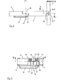
- the window cleaner consists of a carrier strip 1 with a wiper part 2 inserted therein in the form of a rubber strip with a lip profile, a grip part 3 and a receiving part 4 pivotably mounted thereon for a conventional round or polygonal handle 5.
- the grip part 3 engages on the one hand at an angle on the carrier strip 1 and is on the other hand connected via an axis perpendicular to the drawing plane according to FIG. 1 to the receiving part 4, which together with the inserted handle 5 can be pivoted about this axis relative to the handle part 3 and can be locked in one or more rotational positions by means of a tensioning lever 6.
- an axle stub 10, 11 is arranged, which together form an axis of rotation for the carrier bar 1.
- holes 12, 13 are provided in the opposite walls of the attachment, one hole 12 being open to the side via an incision 14 with a narrower cross section (see also FIG. 2), see above that the stub axles 10, 11 can be snapped into the holes 12, 13 by sliding the fork legs 7, 8 onto the shoulder 9 of the support bar 1.
- the handle part 3 and the receiving part 4 for the handle 5 each have, as shown in FIG. 2, a shell-like transition part 15 or 16, in the area of which the two parts are reduced to about half their thickness, so that they are not attached in the assembled state merge.
- the pivot axis mentioned at the outset which is shown in FIGS. 2 and 3 with a dash-dotted line 17, is arranged.
- the receiving part 4 has in the region of its transition side 15 a hollow pin 18 (FIGS. 3 and 4) which, like the grip part 4, is split in the direct connection to the transition part 15.
- the gap is designated 19 in FIG.
- the hollow pin 18 forms two radially resilient jaws 20 which engage in a bearing shell 21 on the other transition part 16 of the handle part 3.
- An eccentric 22 engages in the hollow pin 18, which also protrudes into the bearing shell 21.
- the eccentric 22 is seated on the tensioning lever 6, which runs perpendicular to this.
- the eccentric 22 has an axially and radially extending projection 24 similar to a key bit, which engages in a corresponding recess 25, formed in a similar manner to a keyhole, on the end wall of the journal 23 and in any position deviating from the cover position for axially locking the Eccentric and thus also of the hollow pin 18 or the receiving part 4 on the handle part 3.
- the projection 24 can be brought into the cover position with the opening 25, so that the handle part 3 and receiving part l 4 move away from one another in the direction of the pivot axis 17 and can also be brought back into engagement.
- the tensioning lever 6 By turning the tensioning lever 6, the axial locking is then reinserted.
- the bearing shell 21 on the transition part 16 of the grip part 3 has three depressions 26 on each side on opposite sides, while the jaws 20 of the hollow pin 18 each have a projection 27 at diametrically opposite points.
- the projections 27 on the jaws 20 each engage in two opposite recesses 26 on the bearing shell 21 of the handle part 3.
- the projections 27 are seated in different recesses 26, so that the position of the receiving part 4 and thus the handle 5 relative to the handle part 3 and thus relative to the carrier bar 1 or the cleaning part 2 can be changed 6 pivoted back into its clamping position shown in Figure 1, so that again a firm connection between ischen handle part 3 and receiving part 4 is present.
- the carrier bar 1 with the cleaning part 2 can rotate freely relative to the handle part 3 about an axis lying in a parallel plane (stub axle 10, 11), while on the other hand the angular position of the handle 5 relative to the handle part 3 and thus relative to the cleaning plate 2 after loosening of the tension lever 6 can change.
- the support bar 1 on the stub axles 10, 11 can, for example, in the position shown in FIG. 2, in which the support bar 1 and the handle are arranged in mutually perpendicular planes, be lifted by a locking mechanism (not shown).
Landscapes
- Cleaning Implements For Floors, Carpets, Furniture, Walls, And The Like (AREA)
- Electric Vacuum Cleaner (AREA)
- Detergent Compositions (AREA)
Priority Applications (1)
| Application Number | Priority Date | Filing Date | Title |
|---|---|---|---|
| AT86102342T ATE66798T1 (de) | 1985-02-22 | 1986-02-24 | Fensterreiniger. |
Applications Claiming Priority (2)
| Application Number | Priority Date | Filing Date | Title |
|---|---|---|---|
| DE8505077U | 1985-02-22 | ||
| DE19858505077U DE8505077U1 (de) | 1985-02-22 | 1985-02-22 | Fensterreiniger |
Publications (3)
| Publication Number | Publication Date |
|---|---|
| EP0192278A2 true EP0192278A2 (fr) | 1986-08-27 |
| EP0192278A3 EP0192278A3 (en) | 1988-02-10 |
| EP0192278B1 EP0192278B1 (fr) | 1991-09-04 |
Family
ID=6777758
Family Applications (1)
| Application Number | Title | Priority Date | Filing Date |
|---|---|---|---|
| EP86102342A Expired - Lifetime EP0192278B1 (fr) | 1985-02-22 | 1986-02-24 | Dispositif de nettoyage des fenêtres |
Country Status (3)
| Country | Link |
|---|---|
| EP (1) | EP0192278B1 (fr) |
| AT (1) | ATE66798T1 (fr) |
| DE (2) | DE8505077U1 (fr) |
Cited By (4)
| Publication number | Priority date | Publication date | Assignee | Title |
|---|---|---|---|---|
| EP0672375A1 (fr) * | 1994-03-17 | 1995-09-20 | Hans Raab | Essuie-vitre |
| JP2023548322A (ja) * | 2020-10-30 | 2023-11-16 | アンガー・マーケティング・インターナショナル・エルエルシー | 伸縮式洗浄用具 |
| US12059112B2 (en) | 2020-07-01 | 2024-08-13 | Jonathan Beaudry | Cleaning implement |
| CN119908622A (zh) * | 2023-10-30 | 2025-05-02 | 深圳银星智能集团股份有限公司 | 一种滚刷组件和清洁设备 |
Family Cites Families (7)
| Publication number | Priority date | Publication date | Assignee | Title |
|---|---|---|---|---|
| US2446401A (en) * | 1946-05-10 | 1948-08-03 | Safeway Specialty Corp | Window cleaner |
| US2681464A (en) * | 1952-02-15 | 1954-06-22 | Edward J Baril | Squeegee and holder |
| US2771623A (en) * | 1952-08-20 | 1956-11-27 | Edward J Baril | Adjustable mounting devices for window cleaning squeegee and other articles |
| US2791027A (en) * | 1953-05-20 | 1957-05-07 | James R Davidson | Scraping and cutting tool |
| CH584027A5 (fr) * | 1974-11-08 | 1977-01-31 | Benz August | |
| DE2529061C3 (de) * | 1975-06-30 | 1979-10-04 | Leifheit International Guenter Leifheit Gmbh, 5408 Nassau | Drehgelenk an der Verlängerungsstange eines zum Reinigen von Fensterscheiben o.dgl. dienenden Fensterwischgerätes |
| DE2844185C2 (de) * | 1978-10-11 | 1980-08-14 | Hans 6602 Dudweiler Raab | Fensterreinigungsgerät |
-
1985
- 1985-02-22 DE DE19858505077U patent/DE8505077U1/de not_active Expired
-
1986
- 1986-02-24 DE DE8686102342T patent/DE3681183D1/de not_active Expired - Lifetime
- 1986-02-24 EP EP86102342A patent/EP0192278B1/fr not_active Expired - Lifetime
- 1986-02-24 AT AT86102342T patent/ATE66798T1/de not_active IP Right Cessation
Cited By (5)
| Publication number | Priority date | Publication date | Assignee | Title |
|---|---|---|---|---|
| EP0672375A1 (fr) * | 1994-03-17 | 1995-09-20 | Hans Raab | Essuie-vitre |
| US12059112B2 (en) | 2020-07-01 | 2024-08-13 | Jonathan Beaudry | Cleaning implement |
| JP2023548322A (ja) * | 2020-10-30 | 2023-11-16 | アンガー・マーケティング・インターナショナル・エルエルシー | 伸縮式洗浄用具 |
| EP4203757A4 (fr) * | 2020-10-30 | 2025-03-19 | Unger Marketing International, LLC | Outil de nettoyage télescopique |
| CN119908622A (zh) * | 2023-10-30 | 2025-05-02 | 深圳银星智能集团股份有限公司 | 一种滚刷组件和清洁设备 |
Also Published As
| Publication number | Publication date |
|---|---|
| DE8505077U1 (de) | 1985-05-15 |
| DE3681183D1 (de) | 1991-10-10 |
| EP0192278A3 (en) | 1988-02-10 |
| EP0192278B1 (fr) | 1991-09-04 |
| ATE66798T1 (de) | 1991-09-15 |
Similar Documents
| Publication | Publication Date | Title |
|---|---|---|
| EP0283811B1 (fr) | Appareil de nettoyage notamment pour nettoyer des vitres | |
| EP0287598A1 (fr) | Appareil portatif pour nettoyer des surfaces lisses, notamment des vitres | |
| EP0768938A1 (fr) | Dispositif permettant la fixation amovible d'appareils de nettoyage | |
| DE3128169C2 (de) | Abnehmbarer Tragegriff | |
| DE19908259A1 (de) | Wischmopplatte mit Schwenkkarretiereinrichtung | |
| DE3105951A1 (de) | "kraftwerkzeug" | |
| CH659613A5 (de) | Befestigungskloben. | |
| DE3136401C2 (de) | Mehrzweck-Reinigungsgerät | |
| DE2617622C2 (de) | Kupplungsnippel zur Verbindung eines Arbeitsgerätes mit einem Stiel | |
| DE9102070U1 (de) | Vorrichtung zum lösbaren Verbinden eines Ausstellarms mit einem Hilfslenker | |
| DE20205279U1 (de) | Umschaltaufbau für einen umsteuerbaren Schraubenschlüssel | |
| EP0192278B1 (fr) | Dispositif de nettoyage des fenêtres | |
| DE7620591U1 (de) | Drehgriff fuer fenster, tueren o.dgl. | |
| DE102021105288A1 (de) | Leicht umkehrbare Umschaltknarre | |
| CH625153A5 (en) | Releasable handle fastening for cleaning appliances, such as brooms, scrubbing brushes or window wipers | |
| EP0536509B1 (fr) | Dispositif de fixation d'un corps de balai ou similaire, à un manche | |
| DE29701179U1 (de) | Reinigungsgerät | |
| DE19959940B4 (de) | Lastträgerfuß | |
| EP0121768B1 (fr) | Dispositif de fixation amovible d'un ustensile de nettoyage à un manche | |
| DE2443190B2 (de) | Abschließbarer Verschluß | |
| EP0704580A2 (fr) | Garniture de douche avec élément de serrage ajustable | |
| DE3813351C2 (fr) | ||
| DE19850772C1 (de) | Stielbefestigung für Putzgeräte | |
| DE2148469A1 (de) | Wasserwaage mit einer im winkel einstellbaren libelle | |
| DE8135062U1 (de) | Farbroller |
Legal Events
| Date | Code | Title | Description |
|---|---|---|---|
| PUAI | Public reference made under article 153(3) epc to a published international application that has entered the european phase |
Free format text: ORIGINAL CODE: 0009012 |
|
| AK | Designated contracting states |
Kind code of ref document: A2 Designated state(s): AT BE CH DE FR GB IT LI LU NL SE |
|
| RBV | Designated contracting states (corrected) |
Designated state(s): AT BE CH DE FR GB IT LI NL SE |
|
| PUAL | Search report despatched |
Free format text: ORIGINAL CODE: 0009013 |
|
| AK | Designated contracting states |
Kind code of ref document: A3 Designated state(s): AT BE CH DE FR GB IT LI NL SE |
|
| 17P | Request for examination filed |
Effective date: 19880716 |
|
| 17Q | First examination report despatched |
Effective date: 19891024 |
|
| GRAA | (expected) grant |
Free format text: ORIGINAL CODE: 0009210 |
|
| AK | Designated contracting states |
Kind code of ref document: B1 Designated state(s): AT BE CH DE FR GB IT LI NL SE |
|
| REF | Corresponds to: |
Ref document number: 66798 Country of ref document: AT Date of ref document: 19910915 Kind code of ref document: T |
|
| REF | Corresponds to: |
Ref document number: 3681183 Country of ref document: DE Date of ref document: 19911010 |
|
| ITF | It: translation for a ep patent filed | ||
| ET | Fr: translation filed | ||
| GBT | Gb: translation of ep patent filed (gb section 77(6)(a)/1977) | ||
| PG25 | Lapsed in a contracting state [announced via postgrant information from national office to epo] |
Ref country code: LI Effective date: 19920229 Ref country code: CH Effective date: 19920229 |
|
| PLBE | No opposition filed within time limit |
Free format text: ORIGINAL CODE: 0009261 |
|
| STAA | Information on the status of an ep patent application or granted ep patent |
Free format text: STATUS: NO OPPOSITION FILED WITHIN TIME LIMIT |
|
| 26N | No opposition filed | ||
| REG | Reference to a national code |
Ref country code: CH Ref legal event code: PL |
|
| EAL | Se: european patent in force in sweden |
Ref document number: 86102342.2 |
|
| PGFP | Annual fee paid to national office [announced via postgrant information from national office to epo] |
Ref country code: GB Payment date: 19960223 Year of fee payment: 11 |
|
| PGFP | Annual fee paid to national office [announced via postgrant information from national office to epo] |
Ref country code: SE Payment date: 19960226 Year of fee payment: 11 |
|
| PGFP | Annual fee paid to national office [announced via postgrant information from national office to epo] |
Ref country code: FR Payment date: 19960228 Year of fee payment: 11 Ref country code: DE Payment date: 19960228 Year of fee payment: 11 |
|
| PGFP | Annual fee paid to national office [announced via postgrant information from national office to epo] |
Ref country code: NL Payment date: 19960229 Year of fee payment: 11 Ref country code: AT Payment date: 19960229 Year of fee payment: 11 |
|
| PGFP | Annual fee paid to national office [announced via postgrant information from national office to epo] |
Ref country code: BE Payment date: 19960301 Year of fee payment: 11 |
|
| PG25 | Lapsed in a contracting state [announced via postgrant information from national office to epo] |
Ref country code: GB Effective date: 19970224 Ref country code: AT Effective date: 19970224 |
|
| PG25 | Lapsed in a contracting state [announced via postgrant information from national office to epo] |
Ref country code: SE Effective date: 19970225 |
|
| PG25 | Lapsed in a contracting state [announced via postgrant information from national office to epo] |
Ref country code: BE Effective date: 19970228 |
|
| BERE | Be: lapsed |
Owner name: CORONET-WERKE HEINRICH SCHLERF G.M.B.H. Effective date: 19970228 |
|
| PG25 | Lapsed in a contracting state [announced via postgrant information from national office to epo] |
Ref country code: NL Effective date: 19970901 |
|
| GBPC | Gb: european patent ceased through non-payment of renewal fee |
Effective date: 19970224 |
|
| PG25 | Lapsed in a contracting state [announced via postgrant information from national office to epo] |
Ref country code: FR Effective date: 19971030 |
|
| PG25 | Lapsed in a contracting state [announced via postgrant information from national office to epo] |
Ref country code: DE Effective date: 19971101 |
|
| EUG | Se: european patent has lapsed |
Ref document number: 86102342.2 |
|
| NLV4 | Nl: lapsed or anulled due to non-payment of the annual fee |
Effective date: 19970901 |
|
| REG | Reference to a national code |
Ref country code: FR Ref legal event code: ST |
|
| PG25 | Lapsed in a contracting state [announced via postgrant information from national office to epo] |
Ref country code: IT Free format text: LAPSE BECAUSE OF NON-PAYMENT OF DUE FEES Effective date: 20050224 |