EP0192308A2 - Behälter zum Aufstellen an einer festen Stelle auf dem Boden und Verfahren zur Herstellung des Behälters - Google Patents
Behälter zum Aufstellen an einer festen Stelle auf dem Boden und Verfahren zur Herstellung des Behälters Download PDFInfo
- Publication number
- EP0192308A2 EP0192308A2 EP86200240A EP86200240A EP0192308A2 EP 0192308 A2 EP0192308 A2 EP 0192308A2 EP 86200240 A EP86200240 A EP 86200240A EP 86200240 A EP86200240 A EP 86200240A EP 0192308 A2 EP0192308 A2 EP 0192308A2
- Authority
- EP
- European Patent Office
- Prior art keywords
- reservoir
- upright wall
- piles
- foregoing
- wire mesh
- Prior art date
- Legal status (The legal status is an assumption and is not a legal conclusion. Google has not performed a legal analysis and makes no representation as to the accuracy of the status listed.)
- Granted
Links
- 238000000034 method Methods 0.000 title claims description 6
- 238000004519 manufacturing process Methods 0.000 title claims description 5
- 210000003608 fece Anatomy 0.000 claims abstract description 5
- 239000007788 liquid Substances 0.000 claims abstract description 5
- 239000010871 livestock manure Substances 0.000 claims abstract description 5
- 230000000284 resting effect Effects 0.000 claims abstract description 5
- 150000003839 salts Chemical class 0.000 claims abstract description 4
- 239000007787 solid Substances 0.000 claims abstract description 4
- 238000003892 spreading Methods 0.000 claims abstract description 4
- 239000003245 coal Substances 0.000 claims abstract description 3
- 239000000047 product Substances 0.000 claims abstract description 3
- 238000003860 storage Methods 0.000 claims abstract description 3
- 230000009182 swimming Effects 0.000 claims abstract description 3
- 238000010276 construction Methods 0.000 claims description 19
- 239000004567 concrete Substances 0.000 claims description 18
- 239000000463 material Substances 0.000 claims description 9
- XLYOFNOQVPJJNP-UHFFFAOYSA-N water Substances O XLYOFNOQVPJJNP-UHFFFAOYSA-N 0.000 claims description 7
- 238000005187 foaming Methods 0.000 claims description 6
- 238000007667 floating Methods 0.000 claims description 3
- 239000004568 cement Substances 0.000 claims description 2
- 150000001875 compounds Chemical class 0.000 claims description 2
- 230000008646 thermal stress Effects 0.000 claims description 2
- 238000006073 displacement reaction Methods 0.000 claims 1
- 239000011888 foil Substances 0.000 description 15
- 238000007789 sealing Methods 0.000 description 5
- 239000012528 membrane Substances 0.000 description 3
- 238000009416 shuttering Methods 0.000 description 3
- 230000035882 stress Effects 0.000 description 3
- 229910000831 Steel Inorganic materials 0.000 description 2
- 238000004873 anchoring Methods 0.000 description 2
- 230000008878 coupling Effects 0.000 description 2
- 238000010168 coupling process Methods 0.000 description 2
- 238000005859 coupling reaction Methods 0.000 description 2
- 238000009826 distribution Methods 0.000 description 2
- 239000004576 sand Substances 0.000 description 2
- 239000010959 steel Substances 0.000 description 2
- 238000005273 aeration Methods 0.000 description 1
- 230000003467 diminishing effect Effects 0.000 description 1
- 238000005553 drilling Methods 0.000 description 1
- 230000002706 hydrostatic effect Effects 0.000 description 1
- 238000003780 insertion Methods 0.000 description 1
- 230000037431 insertion Effects 0.000 description 1
- 239000013521 mastic Substances 0.000 description 1
- 239000011513 prestressed concrete Substances 0.000 description 1
- 239000011150 reinforced concrete Substances 0.000 description 1
- 239000000126 substance Substances 0.000 description 1
- 229920002994 synthetic fiber Polymers 0.000 description 1
- 239000004758 synthetic textile Substances 0.000 description 1
Images



Classifications
-
- E—FIXED CONSTRUCTIONS
- E04—BUILDING
- E04H—BUILDINGS OR LIKE STRUCTURES FOR PARTICULAR PURPOSES; SWIMMING OR SPLASH BATHS OR POOLS; MASTS; FENCING; TENTS OR CANOPIES, IN GENERAL
- E04H7/00—Construction or assembling of bulk storage containers employing civil engineering techniques in situ or off the site
- E04H7/02—Containers for fluids or gases; Supports therefor
-
- B—PERFORMING OPERATIONS; TRANSPORTING
- B65—CONVEYING; PACKING; STORING; HANDLING THIN OR FILAMENTARY MATERIAL
- B65D—CONTAINERS FOR STORAGE OR TRANSPORT OF ARTICLES OR MATERIALS, e.g. BAGS, BARRELS, BOTTLES, BOXES, CANS, CARTONS, CRATES, DRUMS, JARS, TANKS, HOPPERS, FORWARDING CONTAINERS; ACCESSORIES, CLOSURES, OR FITTINGS THEREFOR; PACKAGING ELEMENTS; PACKAGES
- B65D88/00—Large containers
- B65D88/02—Large containers rigid
- B65D88/06—Large containers rigid cylindrical
- B65D88/08—Large containers rigid cylindrical with a vertical axis
-
- B—PERFORMING OPERATIONS; TRANSPORTING
- B65—CONVEYING; PACKING; STORING; HANDLING THIN OR FILAMENTARY MATERIAL
- B65D—CONTAINERS FOR STORAGE OR TRANSPORT OF ARTICLES OR MATERIALS, e.g. BAGS, BARRELS, BOTTLES, BOXES, CANS, CARTONS, CRATES, DRUMS, JARS, TANKS, HOPPERS, FORWARDING CONTAINERS; ACCESSORIES, CLOSURES, OR FITTINGS THEREFOR; PACKAGING ELEMENTS; PACKAGES
- B65D90/00—Component parts, details or accessories for large containers
- B65D90/02—Wall construction
- B65D90/023—Modular panels
- B65D90/024—Modular panels with features of cylindrical curvature
-
- E—FIXED CONSTRUCTIONS
- E04—BUILDING
- E04H—BUILDINGS OR LIKE STRUCTURES FOR PARTICULAR PURPOSES; SWIMMING OR SPLASH BATHS OR POOLS; MASTS; FENCING; TENTS OR CANOPIES, IN GENERAL
- E04H4/00—Swimming or splash baths or pools
- E04H4/0018—Easily movable or transportable swimming pools
- E04H4/0043—Easily movable or transportable swimming pools mainly made of panels
- E04H4/005—Easily movable or transportable swimming pools mainly made of panels characterised by the framework for supporting the panels
Definitions
- the invention relates to a reservoir for placing in a fixed position on the ground, for example a swimming pool or a storage tank for liquid and/or solid (bulk) goods having little or no cohesion, for example crop products, coal, manure, spreading salt and the like, having at least a bottom and an upright wall connecting thereto which is resistant to outwardly directed pressure.
- a reservoir for placing in a fixed position on the ground for example a swimming pool or a storage tank for liquid and/or solid (bulk) goods having little or no cohesion, for example crop products, coal, manure, spreading salt and the like, having at least a bottom and an upright wall connecting thereto which is resistant to outwardly directed pressure.
- a reservoir for placing in a fixed position on the ground, for example a swimming pool or a storage tank for liquid and/or solid (bulk) goods having little or no cohesion, for example crop products, coal, manure, spreading salt and the like, having at least a bottom and an upright wall connecting thereto which is resistant to outwardly
- Such a reservoir is known in various forms.
- a current form is one in which the upright wall is formed by concrete or, if required, reinforced concrete.
- Such a reservoir has the drawback that it is comparatively expensive, as much because of the quantity of material required as the method of manufacturing that has to be followed, namely the placing of shutterings, the filling of these shutterings by pouring and their subsequent removal. This method does not moreover lead itself to application by little trained users.
- the invention has for its object to now make a reservoir in a form such that it can be built very simply and with little knowledge and training at comparatively low cost.
- the invention provides to this end a reservoir of. the type referred to in the preamble which displays the feature that the upright wall consists of a number of vertical piles placed in a closed configuration at intervals from one another, a vertical wire mesh arranged between these piles and a bottom element extending on the bottom, on which element an upright wall part is formed or arranged resting against the inner side of the said wire mesh.
- Each pile can consist advantageously of a vertical pile driven into the ground and anchored if necessary by cement or concrete.
- a very simple variant is one in which each pile inserted into this tube takes the form of a tube filled by pouring.
- the bottom is capable of good plastic deformation while preserving the required properties, for example impermeability to water
- the bottom can consist of a several centimeter thick layer of (foaming) concrete arranged on the ground and a subsequent plastic membrane impermeable to water, onto which another layer of (foaming) concrete is arranged.
- This construction has the advantage of having a long deformation line and of adapting easily if necessary to small changes in the around structure.
- an embodiment can be applied which has the feature that between the vertical wire mesh attached to the vertical piles and the upright wall is arranged a substantially rigid board for distributing outwardly directed forces.
- Yet another embodiment can display the feature that in addition to the upright wall part resting against the inner side of the piles, an upright wall part is arranged extending around the outer side of the piles and the space between both these wall parts is filled by pouring with a curing material such as (floating) concrete.
- a curing material such as (floating) concrete.
- a possibly slack roof covering which extends over the upper edge of the upright wall and is supported in the centre by for example a constructed horizontal beam.
- the supporting beam can support on the bottom of the reservoir.
- the supporting beam can advantageously consist of a construction consisting of tubes filled by pouring, whereby the tubes form for example the ribs of a cube.
- the reservoir according to the invention can display the characteristic that the upright wall is provided close to its upper edge and above the maximum filling level of the reservoir with at least one gas outlet duct connecting to a tube with water seal.
- Such an embodiment is particularly of practical importance in the case of a reservoir serving as manure store.
- the invention extends to a method for manufacturing such a reservoir.
- This method can have the feature that, after levelling the ground where required, the reservoir bottom is laid thereon, that around this bottom vertical tubes are placed in the ground at intervals from one another, that upright piles are placed in these tubes, that these piles are anchored therein by a filling compound, that to the inner side of these piles is attached a circumferentially closed upright wire mesh and that a wall part formed or arranged on the bottom part is arranged against this wire mesh, covering same.
- Fig. 1 shows a bottom 1 consisting of a layer 3 of (foaming) concrete arranged on the ground 2, the concrete having arranged on it an impermeable membrane 4, on which is placed a layer of (foaming) concrete 5.
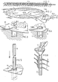
- Fig. 2 shows the laying of membrane or foil 4. This is round in shape and displays on its circumference holes 6 arranged at regular mutual intervals having radial slots 7 open to outside, as is shown in more detail in fig. 3. These holes and slots are arranged in the edge zone 28. On the inner side of the edge zone is arranged a cylindrical casing shaped foil part 8 intended for the forming of an upright wall part.
- tubes 10 are placed therein, these tubes being provided on their underside with horizontal bearing pins 1 1 which serve in the way shown in fig. 5 to support a pile 1 2 to be placed later.
- Such a pile can take the form of a tube later filled by pouring with concrete 13.
- Fig. 6 shows the manner of attaching wire mesh members 14 on pile 12. These horizontal wire mesh members 14 display on their ends loops consisting of an end that is bent round and welded.
- connections 15, 16 are positioned outside the yet to be placed reservoir such that the user can fill and empty the reservoir using his own means.
- lines 17, 1 8 which emerge above foil 4. This aspect will be discussed further in reference to fig. 32.
- F ig. 7 shows how wire meshes 19 are linked with vertical piles 12.
- boards 20 are arranged against wire mesh 19 on the inner side for the distribution of the force which the filling of a reservoir applies to the wire meshes.
- one board extends between two adjacent piles.
- a strip 89 is arranged on the inner side over the seam between boards 20. This is attached to only one board, in order to avoid possible thermal stress.
- wire meshes 21 are arranged between piles 12 leaving an intermediate pile free; the same applies to the associated boards 22.
- Fig. 10 shows a completed reservoir 23 in an embodiment, namely one in which the wire meshes are accessible on the outer side.
- Fig. 11 shows a possible way of attaching upright foil part 8 to wire meshes 19, namely by means of hooks 24.
- Fig. 12 shows edge zone 28 which in this embodiment is provided with tensioning lips 25 arranged with a regular distribution and extending in radial direction, which serve to tighten foil 4.
- Fig. 13 shows this latter in the final configuration.
- Fig. 14 shows a variant in which edge zone 28 is provided with an extra edge zone 26 having tensile strength which serves to replace tensioning lips 25. Edge zone 26 will be further mentioned in reference to fig. 16 and 17.
- Fig. 1 5 shows a completed reservoir 29. This differs from reservoir 23 according to fig. 10 in that wire meshes 19 are no longer visible but are covered by wall parts 30 extending on the outer side. These wall parts can take the form of foil or reinforced synthetic textile strip or the like.
- Fig. 16 and 17 show the construction of the said wall parts 30 as according to fig. 15. As is seen in these figures, another wall part 30 is arranged outside each wire mesh 1 9 such that a pouring space results which is filled with a layer 31 of (foaming) concrete in the way indicated in these figures.
- edge zone 26 having tensioning strength is placed on the ground 2, while in the embodiment according to fig. 17 edge zone 26 with the lower edge zone of wall part 30 coupled thereto is entrenched in the ground 2.
- the concrete wall is supported by a slide layer 90, over which edge zone 28 can slide in the case of load variations, for example varying fillings and temperature variations.
- the reservoir Prior to filling the pouring spaces with concrete 31 in the embodiment according to figures 15, 16, 17 the reservoir is filled with the material it is intended for, such as water, spreading salt, sand or the like. In this way the wall construction comes under tensile stress. Filling by pouring under this stress results in a construction analogous to that of prestressed concrete. Without going into details it can be stated that the pouring height must be selected to conform with the specific weight of the pouring material and that of the filling of the reservoir. A partially prestressed construction is thus obtained in a very simple manner with all the resulting advantages, particularly in the unfilled state.
- Fig. 18 shows a reservoir 32 having an upright wall part 33 the outwardly directed force of which is absorbed by tensioned ropes 34. Attention is drawn to the fact that the mutual spacing of ropes 34 becomes greater with increasing height in view of the diminishing hydrostatic pressure, wholly analogous to the construction of wire meshes 19, 21 according to the fig. 7, 8, 9.
- the vertical piles consist in this case of substantially omega shaped profiled beams 35 with recesses 36 (see fig. 21) for the passage of ropes 34.
- Wall parts 33 are anchored in bottom 37 by anchoring members 38.
- a foil 39 On bottom 37 is placed a foil 39. The edge of this is sealing connected with wall part 33 by a weld zone 40. In the absence of foil, a mastic joint can be applied.
- Fig. 19 shows an alternative in which anchoring members 38 are omitted.
- a plastic foil 41 is situated under the bottom 37.
- Fig. 20 shows a reservoir 42 having two wall parts 33 which are held together by ropes 34 which also co-operate with beams 35.
- overlapping zones 43 present of the adjoining wall parts 33. These latter are sealing coupled there with one another.
- Fig. 22 shows how this coupling is carried out. Between both boards is located a rubber sealing strip 44, while two connecting strips 45 and 46 respectively are placed on the inner and outer side and coupled by bolts/nuts 47.
- Fig. 21 shows the construction of the omega shaped beams 35 and the manner of fixing of ropes 34.
- Fig. 23 shows the coupling element 48 as illustrated in fig. 20. It consists of a housing into which the ends of rope 34 are inserted, after which the housing is filled with a curing plastic.
- Fig. 24 shows a cube-shaped structure 49 which serves as roof support.
- This support 49 comprises tubular parts 50 which are connected to one another with corner elements 51 and, as is indicated symbolically by a funnel 52, are filled by pouring with for example concrete or sand.
- Fig. 25 shows a reservoir 53 with a roof support 54 which is constructed in accordance with the embodiment as in fig. 24.
- Fig. 26 shows an upper edge of a reservoir which is provided with a cover 55 (see also fig. 25), this cover displaying at least one opening 56, which connects with the environment via a water seal 57.
- a roof 58 consists of a foil that is supported in the centre by support 54 and connected at the edges to edge 5-9.
- Fig. 27 shows, in contrast to the fixed connection 60 of roof 58 with wall part 30, that roof 58 can be provided along its circumference with loops 61 which can be hooked round knobs 62 in the way shown in fig. 28.
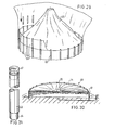
- Fig. 29 shows that use can also be made of connectable vertical piles 63, namely piles having a lower part 64 of smaller diameter, such that this lower part fits inside the upper part of another identical pile. In this way any required height of a reservoir according to the invention can in principle be realised.
- Fig. 29 also shows the way in which the sack 65 serving as impermeable foil can in this case be placed so as to be later folded outwards such that it comes to rest against the members 66 having tensile strength, such as ropes or wire meshes, which are arranged between piles 63.
- Fig. 31 shows a pile 63 in detail.
- the uppermost pile can be closed by means of a stopper 67.
- Fig. 30 shows a reservoir 68 which is filled with a liquid 69 on which rests a covering 70.
- a covering 70 rests a foil form roof 71.
- Fig. 32 shows another possible bearing construction for a roof.
- This bearing construction comprises a vertical hollow pipe 72 on the upper part of which is attached a collar 73 provided with supporting eyes 74 for radial bars 75 the ends of which can be bent over to rest on the annular cover 55.
- a cover with supporting eyes or hole which is placed on pipe 72.
- Pipe 72 is provided with holes 76 and an upper end open for de-aeration. It is supported by a table 78 which is supported by supports 79. Under these emerges a feed/outlet pipe 80. Supports 79 bear on a flange construction 81 which co-operates with sealing via an impermeable foil 82 and a bottom part 83 with a flange part 84 which is joined to a pipe connection 85.
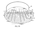
- fig. 33 shows schematically a reservoir 86 that is provided with a feed system 87 and a draining system 88 having a sample pit 91.
- the fixing tubes that are to be placed in the ground can consist of any suitable material, for example PVC.
- PVC polyvinyl styrene
- the wire meshes can be placed in register, after which the piles or steel tubes 12 are placed and arranged in the positioning tubes 10. This operation can if desired be prepared per group. After its completion steel tubes 12 can if necessary be filled in the way indicated in fig. 6 with a curing material such as concrete in order to prevent deformation under load.
- an extra interior covering may or may not be necessary.
- outer wall parts 30 and the filling by pouring with for example concrete 31 can be omitted.
- the REKO boards can be provided with an overlapping or free end zone with connecting piece with a view to expansion/shrinkage, particularly in the case of temperature changes.
- Ropes 34 in the embodiment according to fig. 18, 20, 21, 22, 23 can be of the type on the market under the trade name "POLYSTAL".
- connections 15 and 16 are placed such that the user can transport in this case manure to and from the reservoir using his own means without an extra pump.
Landscapes
- Engineering & Computer Science (AREA)
- Architecture (AREA)
- Civil Engineering (AREA)
- Structural Engineering (AREA)
- Mechanical Engineering (AREA)
- General Engineering & Computer Science (AREA)
- Revetment (AREA)
- Waveguide Aerials (AREA)
- Control Of Motors That Do Not Use Commutators (AREA)
- Sewage (AREA)
- Underground Structures, Protecting, Testing And Restoring Foundations (AREA)
- Supplying Of Containers To The Packaging Station (AREA)
- Vehicle Cleaning, Maintenance, Repair, Refitting, And Outriggers (AREA)
- Investigation Of Foundation Soil And Reinforcement Of Foundation Soil By Compacting Or Drainage (AREA)
- Conveying And Assembling Of Building Elements In Situ (AREA)
- Containers Having Bodies Formed In One Piece (AREA)
- Road Paving Structures (AREA)
Priority Applications (1)
| Application Number | Priority Date | Filing Date | Title |
|---|---|---|---|
| AT86200240T ATE72475T1 (de) | 1985-02-21 | 1986-02-18 | Behaelter zum aufstellen an einer festen stelle auf dem boden und verfahren zur herstellung des behaelters. |
Applications Claiming Priority (4)
| Application Number | Priority Date | Filing Date | Title |
|---|---|---|---|
| NL8500497A NL8500497A (nl) | 1985-02-21 | 1985-02-21 | Reservoir en werkwijze voor het vervaardigen daarvan. |
| NL8500497 | 1985-02-21 | ||
| NL8503003A NL8503003A (nl) | 1985-02-21 | 1985-11-01 | Op een vaste plaats op de grond te plaatsen reservoir en werkwijze voor het vervaardigen daarvan. |
| NL8503003 | 1985-11-01 |
Publications (3)
| Publication Number | Publication Date |
|---|---|
| EP0192308A2 true EP0192308A2 (de) | 1986-08-27 |
| EP0192308A3 EP0192308A3 (en) | 1987-05-27 |
| EP0192308B1 EP0192308B1 (de) | 1992-02-05 |
Family
ID=26646026
Family Applications (1)
| Application Number | Title | Priority Date | Filing Date |
|---|---|---|---|
| EP86200240A Expired EP0192308B1 (de) | 1985-02-21 | 1986-02-18 | Behälter zum Aufstellen an einer festen Stelle auf dem Boden und Verfahren zur Herstellung des Behälters |
Country Status (7)
| Country | Link |
|---|---|
| US (1) | US4756033A (de) |
| EP (1) | EP0192308B1 (de) |
| AT (1) | ATE72475T1 (de) |
| CA (1) | CA1284264C (de) |
| DE (1) | DE3683781D1 (de) |
| DK (1) | DK167409B1 (de) |
| NL (1) | NL8503003A (de) |
Cited By (4)
| Publication number | Priority date | Publication date | Assignee | Title |
|---|---|---|---|---|
| FR2642735A1 (fr) * | 1989-02-03 | 1990-08-10 | Artix Sa | Armature pour structure legere formant reservoir de liquide et reservoirs pourvus de cette armature |
| EP0519124A1 (de) * | 1991-06-21 | 1992-12-23 | Hendrik Willem Schelfhorst | Dach für einen Silo oder dergleichen |
| ITFI20100002A1 (it) * | 2010-01-07 | 2011-07-08 | Daniele Pianigiani | Vasca per attivita' sportive e/o ludiche. |
| FR3133400A1 (fr) * | 2022-03-08 | 2023-09-15 | Mathieu PORTELLI | Structure de piscine hors sol et son procede de montage |
Families Citing this family (19)
| Publication number | Priority date | Publication date | Assignee | Title |
|---|---|---|---|---|
| US4860916A (en) * | 1988-09-15 | 1989-08-29 | Environetics, Inc. | Tank and method of making same |
| US5192162A (en) * | 1991-11-08 | 1993-03-09 | Mckinnon Gordon | Pool apparatus and method of making |
| US5419656A (en) * | 1991-11-08 | 1995-05-30 | Mckinnon; Gordon | Pool apparatus and method of making |
| US5833007A (en) * | 1994-05-23 | 1998-11-10 | Jean-Noel M. Guyot | Container for manure |
| USD394907S (en) | 1996-10-18 | 1998-06-02 | Pacific Industries, Inc. | Pool |
| US5791099A (en) * | 1996-10-18 | 1998-08-11 | Pacific Industries, Inc. | Multi-walled, sectional swimming pool fabricated of preformed plastic or resin |
| US5732753A (en) * | 1996-12-31 | 1998-03-31 | Danzi; Robert | Concrete wall form aligning funnel system |
| US6108972A (en) * | 1998-02-23 | 2000-08-29 | Solis; George Patrick | Apparatus for and methods of bracing soil, retaining water, and blocking roots |
| FR2856332B1 (fr) * | 2003-06-20 | 2007-03-23 | Piscines Desjoyaux Sa | Panneau pour la realisation d'un bassin de piscine |
| US7390141B2 (en) * | 2004-06-03 | 2008-06-24 | Rytand David H | Wave-attenuating system |
| AT501866B1 (de) * | 2005-05-23 | 2007-07-15 | Federspiel Per G Mag Dr | Flachboden-tankanlage für die lagerung von brennbaren und/oder umweltschädigenden flüssigkeiten |
| ES2336516B1 (es) * | 2007-06-13 | 2011-03-11 | Alpi Sistemas, S.L. | Sistema de encofrado perdido de material plastico. |
| US8136177B2 (en) * | 2010-01-20 | 2012-03-20 | Kuo-Ying Kan | Assembled water reservoir |
| US8794872B2 (en) * | 2012-08-16 | 2014-08-05 | Alf Kolbjoern Sevre | Method for constructing membrane lined structures for holding large fluid volumes |
| US10081487B2 (en) | 2012-10-11 | 2018-09-25 | Allied Steel | Secondary containment |
| US11230853B2 (en) | 2013-04-24 | 2022-01-25 | JWF Industries | Large capacity above ground impoundment tank |
| IL232751B (en) * | 2014-05-22 | 2019-03-31 | Avi Victor Romano | Industrial pool |
| RU180668U1 (ru) * | 2017-12-06 | 2018-06-21 | Валерий Павлович Левицкий | Надземное каркасное водохранилище |
| US10625185B1 (en) * | 2019-03-01 | 2020-04-21 | Precision Dewatering, Llc | Portable filtration apparatus, systems and methods |
Citations (3)
| Publication number | Priority date | Publication date | Assignee | Title |
|---|---|---|---|---|
| CH396351A (de) | 1961-06-28 | 1965-07-31 | Kneubuehl Fritz | Zerlegbares Badebassin |
| GB1049272A (en) | 1965-02-11 | 1966-11-23 | Drix Products Ltd | Improvements in or relating to swimming or bathing pools |
| EP0060084A1 (de) | 1981-03-03 | 1982-09-15 | Leigh Flexible Structures Limited | Speicherbehälter |
Family Cites Families (15)
| Publication number | Priority date | Publication date | Assignee | Title |
|---|---|---|---|---|
| US865488A (en) * | 1906-12-27 | 1907-09-10 | G A Edward Kohler | Building girder and column. |
| US1065237A (en) * | 1911-10-30 | 1913-06-17 | John Tweddle Graham | Grain-bin. |
| US1153205A (en) * | 1915-02-15 | 1915-09-14 | William C Edwards Jr | Wall-construction apparatus. |
| US1963980A (en) * | 1931-09-05 | 1934-06-26 | Garrett Neal | Structure |
| US2315894A (en) * | 1940-10-16 | 1943-04-06 | John M Crom | Concrete construction |
| US2748904A (en) * | 1951-09-25 | 1956-06-05 | Arndt Raymond | Corn crib |
| US2815512A (en) * | 1955-12-08 | 1957-12-10 | Hettrick Mfg Co | Swimming pool structure |
| US3008148A (en) * | 1960-07-18 | 1961-11-14 | Jacob A Vierling | Polygonal swimming pool cover |
| GB1133476A (en) * | 1965-12-04 | 1968-11-13 | G K N Reinforcements Ltd | Improvements in or relating to storage tanks and swimming pools |
| US3468088A (en) * | 1966-04-14 | 1969-09-23 | Clarence J Miller | Wall construction |
| GB1207966A (en) * | 1966-11-16 | 1970-10-07 | Cherwell Valley Silos | Improvements in silos |
| US3608099A (en) * | 1969-10-20 | 1971-09-28 | Domain Ind Inc | Swimming pool cover |
| US3847184A (en) * | 1972-10-05 | 1974-11-12 | A God | Metal pipe with spaced flexible portions |
| US4267676A (en) * | 1979-02-26 | 1981-05-19 | Preload Technology, Inc. | Earthquake resisting tank and methods of constructing same |
| AU9181582A (en) * | 1982-01-05 | 1983-07-14 | J.R. Wyllie & Sons Pty Ltd | Metal tanks |
-
1985
- 1985-11-01 NL NL8503003A patent/NL8503003A/nl not_active Application Discontinuation
-
1986
- 1986-02-18 US US06/829,965 patent/US4756033A/en not_active Expired - Fee Related
- 1986-02-18 CA CA000502125A patent/CA1284264C/en not_active Expired - Lifetime
- 1986-02-18 EP EP86200240A patent/EP0192308B1/de not_active Expired
- 1986-02-18 DE DE8686200240T patent/DE3683781D1/de not_active Expired - Lifetime
- 1986-02-18 AT AT86200240T patent/ATE72475T1/de not_active IP Right Cessation
- 1986-02-19 DK DK077586A patent/DK167409B1/da not_active IP Right Cessation
Patent Citations (3)
| Publication number | Priority date | Publication date | Assignee | Title |
|---|---|---|---|---|
| CH396351A (de) | 1961-06-28 | 1965-07-31 | Kneubuehl Fritz | Zerlegbares Badebassin |
| GB1049272A (en) | 1965-02-11 | 1966-11-23 | Drix Products Ltd | Improvements in or relating to swimming or bathing pools |
| EP0060084A1 (de) | 1981-03-03 | 1982-09-15 | Leigh Flexible Structures Limited | Speicherbehälter |
Cited By (5)
| Publication number | Priority date | Publication date | Assignee | Title |
|---|---|---|---|---|
| FR2642735A1 (fr) * | 1989-02-03 | 1990-08-10 | Artix Sa | Armature pour structure legere formant reservoir de liquide et reservoirs pourvus de cette armature |
| EP0519124A1 (de) * | 1991-06-21 | 1992-12-23 | Hendrik Willem Schelfhorst | Dach für einen Silo oder dergleichen |
| US5444943A (en) * | 1991-06-21 | 1995-08-29 | Schelfhorst; Hendrik W. | Roof for a silo or the like |
| ITFI20100002A1 (it) * | 2010-01-07 | 2011-07-08 | Daniele Pianigiani | Vasca per attivita' sportive e/o ludiche. |
| FR3133400A1 (fr) * | 2022-03-08 | 2023-09-15 | Mathieu PORTELLI | Structure de piscine hors sol et son procede de montage |
Also Published As
| Publication number | Publication date |
|---|---|
| EP0192308A3 (en) | 1987-05-27 |
| ATE72475T1 (de) | 1992-02-15 |
| EP0192308B1 (de) | 1992-02-05 |
| US4756033A (en) | 1988-07-12 |
| DE3683781D1 (de) | 1992-03-19 |
| DK77586A (da) | 1986-08-22 |
| DK167409B1 (da) | 1993-10-25 |
| CA1284264C (en) | 1991-05-21 |
| NL8503003A (nl) | 1986-09-16 |
| DK77586D0 (da) | 1986-02-19 |
Similar Documents
| Publication | Publication Date | Title |
|---|---|---|
| US4756033A (en) | Reservoir for placing in a fixed position on the ground and method for manufacturing same | |
| EP0123401B1 (de) | Turmkonstruktion und Verfahren zum Herstellen einer solchen Konstruktion | |
| US3736754A (en) | Reservoirs for the storage of liquids especially volatile liquids | |
| US4961293A (en) | Precast, prestressed concrete secondary containment vault | |
| KR101223667B1 (ko) | 프리캐스트 콘크리트 패널을 이용한 관개용수로 및 이 시공방법 | |
| US4075801A (en) | Storage tanks | |
| US4818151A (en) | Secondary containment systems especially well suited for hydrocarbon storage and delivery systems | |
| US20050210795A1 (en) | Method for constructing a plastic lined concrete structure and structure built thereby | |
| US4879859A (en) | Method and apparatus for constructing circumferentially wrapped prestressed structures utilizing a membrane | |
| US3712002A (en) | Silo container respectively silo construction | |
| US4602463A (en) | Tank construction having a floor formed of interconnected panels | |
| US5857293A (en) | Flexible formwork assembly | |
| KR101698916B1 (ko) | 응급 물막이 장치를 이용한 차수벽 시공방법 | |
| US3707850A (en) | Cryogenic storage tank improvements | |
| EP3757294A1 (de) | Schnell einsetzbares hochwasserabwehrsystem | |
| US4776145A (en) | Multi purpose dome structure and the construction thereof | |
| US5134830A (en) | Method and apparatus for constructing circumferentially wrapped prestressed structures utilizing a membrane | |
| DE1434598A1 (de) | Dachkonstruktion fuer im Erdboden eingelassene Behaelter | |
| US4813200A (en) | Large container for pourable, pasty and sludge-like materials and a method of using the same | |
| JPH0415680Y2 (de) | ||
| US3106045A (en) | Swimming pools and like structures of the type having endless peripheral metal walls | |
| US7000800B2 (en) | Storage tank assembly | |
| AU2001242562A1 (en) | Improved storage tank assembly | |
| EP0060084A1 (de) | Speicherbehälter | |
| US20070068100A1 (en) | Footing tube foundation |
Legal Events
| Date | Code | Title | Description |
|---|---|---|---|
| PUAI | Public reference made under article 153(3) epc to a published international application that has entered the european phase |
Free format text: ORIGINAL CODE: 0009012 |
|
| AK | Designated contracting states |
Kind code of ref document: A2 Designated state(s): AT BE CH DE FR GB IT LI LU NL SE |
|
| PUAL | Search report despatched |
Free format text: ORIGINAL CODE: 0009013 |
|
| AK | Designated contracting states |
Kind code of ref document: A3 Designated state(s): AT BE CH DE FR GB IT LI LU NL SE |
|
| 17P | Request for examination filed |
Effective date: 19871117 |
|
| 17Q | First examination report despatched |
Effective date: 19890116 |
|
| ITF | It: translation for a ep patent filed | ||
| GRAA | (expected) grant |
Free format text: ORIGINAL CODE: 0009210 |
|
| AK | Designated contracting states |
Kind code of ref document: B1 Designated state(s): AT BE CH DE FR GB IT LI LU NL SE |
|
| REF | Corresponds to: |
Ref document number: 72475 Country of ref document: AT Date of ref document: 19920215 Kind code of ref document: T |
|
| REF | Corresponds to: |
Ref document number: 3683781 Country of ref document: DE Date of ref document: 19920319 |
|
| ET | Fr: translation filed | ||
| PLBE | No opposition filed within time limit |
Free format text: ORIGINAL CODE: 0009261 |
|
| STAA | Information on the status of an ep patent application or granted ep patent |
Free format text: STATUS: NO OPPOSITION FILED WITHIN TIME LIMIT |
|
| 26N | No opposition filed | ||
| ITTA | It: last paid annual fee | ||
| EPTA | Lu: last paid annual fee | ||
| EAL | Se: european patent in force in sweden |
Ref document number: 86200240.9 |
|
| PGFP | Annual fee paid to national office [announced via postgrant information from national office to epo] |
Ref country code: AT Payment date: 19960222 Year of fee payment: 11 |
|
| PGFP | Annual fee paid to national office [announced via postgrant information from national office to epo] |
Ref country code: SE Payment date: 19960223 Year of fee payment: 11 Ref country code: GB Payment date: 19960223 Year of fee payment: 11 Ref country code: FR Payment date: 19960223 Year of fee payment: 11 |
|
| PGFP | Annual fee paid to national office [announced via postgrant information from national office to epo] |
Ref country code: NL Payment date: 19960229 Year of fee payment: 11 Ref country code: DE Payment date: 19960229 Year of fee payment: 11 |
|
| PGFP | Annual fee paid to national office [announced via postgrant information from national office to epo] |
Ref country code: BE Payment date: 19960320 Year of fee payment: 11 |
|
| PGFP | Annual fee paid to national office [announced via postgrant information from national office to epo] |
Ref country code: LU Payment date: 19960401 Year of fee payment: 11 |
|
| PGFP | Annual fee paid to national office [announced via postgrant information from national office to epo] |
Ref country code: CH Payment date: 19960522 Year of fee payment: 11 |
|
| NLUE | Nl: licence registered with regard to european patents |
Effective date: 19930928 |
|
| PG25 | Lapsed in a contracting state [announced via postgrant information from national office to epo] |
Ref country code: LU Free format text: LAPSE BECAUSE OF NON-PAYMENT OF DUE FEES Effective date: 19970218 Ref country code: GB Effective date: 19970218 Ref country code: AT Effective date: 19970218 |
|
| PG25 | Lapsed in a contracting state [announced via postgrant information from national office to epo] |
Ref country code: SE Effective date: 19970219 |
|
| PG25 | Lapsed in a contracting state [announced via postgrant information from national office to epo] |
Ref country code: LI Effective date: 19970228 Ref country code: CH Effective date: 19970228 Ref country code: BE Effective date: 19970228 |
|
| BERE | Be: lapsed |
Owner name: SCHELFHORST HENDRIK WILLEM Effective date: 19970228 |
|
| PG25 | Lapsed in a contracting state [announced via postgrant information from national office to epo] |
Ref country code: NL Effective date: 19970901 |
|
| GBPC | Gb: european patent ceased through non-payment of renewal fee |
Effective date: 19970218 |
|
| REG | Reference to a national code |
Ref country code: CH Ref legal event code: PL |
|
| PG25 | Lapsed in a contracting state [announced via postgrant information from national office to epo] |
Ref country code: FR Effective date: 19971030 |
|
| PG25 | Lapsed in a contracting state [announced via postgrant information from national office to epo] |
Ref country code: DE Effective date: 19971101 |
|
| EUG | Se: european patent has lapsed |
Ref document number: 86200240.9 |
|
| NLV4 | Nl: lapsed or anulled due to non-payment of the annual fee |
Effective date: 19970901 |
|
| REG | Reference to a national code |
Ref country code: FR Ref legal event code: ST |
|
| PG25 | Lapsed in a contracting state [announced via postgrant information from national office to epo] |
Ref country code: IT Free format text: LAPSE BECAUSE OF NON-PAYMENT OF DUE FEES;WARNING: LAPSES OF ITALIAN PATENTS WITH EFFECTIVE DATE BEFORE 2007 MAY HAVE OCCURRED AT ANY TIME BEFORE 2007. THE CORRECT EFFECTIVE DATE MAY BE DIFFERENT FROM THE ONE RECORDED. Effective date: 20050218 |