EP0192343A2 - Abzugsmechanismussicherung für eine halbautomatische Feuerwaffe - Google Patents
Abzugsmechanismussicherung für eine halbautomatische Feuerwaffe Download PDFInfo
- Publication number
- EP0192343A2 EP0192343A2 EP86300466A EP86300466A EP0192343A2 EP 0192343 A2 EP0192343 A2 EP 0192343A2 EP 86300466 A EP86300466 A EP 86300466A EP 86300466 A EP86300466 A EP 86300466A EP 0192343 A2 EP0192343 A2 EP 0192343A2
- Authority
- EP
- European Patent Office
- Prior art keywords
- firing pin
- hammer
- spring
- striker
- firing
- Prior art date
- Legal status (The legal status is an assumption and is not a legal conclusion. Google has not performed a legal analysis and makes no representation as to the accuracy of the status listed.)
- Withdrawn
Links
- 238000010304 firing Methods 0.000 title claims abstract description 146
- 239000007787 solid Substances 0.000 claims description 10
- 230000000063 preceeding effect Effects 0.000 claims 4
- 238000007599 discharging Methods 0.000 abstract description 3
- 230000006835 compression Effects 0.000 description 12
- 238000007906 compression Methods 0.000 description 12
- 230000000994 depressogenic effect Effects 0.000 description 4
- 230000002093 peripheral effect Effects 0.000 description 4
- 230000000284 resting effect Effects 0.000 description 3
- 230000000881 depressing effect Effects 0.000 description 2
- 230000004308 accommodation Effects 0.000 description 1
- 238000010276 construction Methods 0.000 description 1
- 230000009977 dual effect Effects 0.000 description 1
- 238000004519 manufacturing process Methods 0.000 description 1
- 230000000717 retained effect Effects 0.000 description 1
Images





Classifications
-
- F—MECHANICAL ENGINEERING; LIGHTING; HEATING; WEAPONS; BLASTING
- F41—WEAPONS
- F41A—FUNCTIONAL FEATURES OR DETAILS COMMON TO BOTH SMALLARMS AND ORDNANCE, e.g. CANNONS; MOUNTINGS FOR SMALLARMS OR ORDNANCE
- F41A19/00—Firing or trigger mechanisms; Cocking mechanisms
- F41A19/06—Mechanical firing mechanisms, e.g. counterrecoil firing, recoil actuated firing mechanisms
- F41A19/42—Mechanical firing mechanisms, e.g. counterrecoil firing, recoil actuated firing mechanisms having at least one hammer
- F41A19/43—Mechanical firing mechanisms, e.g. counterrecoil firing, recoil actuated firing mechanisms having at least one hammer in bolt-action guns
-
- F—MECHANICAL ENGINEERING; LIGHTING; HEATING; WEAPONS; BLASTING
- F41—WEAPONS
- F41A—FUNCTIONAL FEATURES OR DETAILS COMMON TO BOTH SMALLARMS AND ORDNANCE, e.g. CANNONS; MOUNTINGS FOR SMALLARMS OR ORDNANCE
- F41A17/00—Safety arrangements, e.g. safeties
- F41A17/64—Firing-pin safeties, i.e. means for preventing movement of slidably- mounted strikers
- F41A17/72—Firing-pin safeties, i.e. means for preventing movement of slidably- mounted strikers trigger-operated, i.e. the movement of the trigger bringing a firing-pin safety into inoperative position during the firing
Definitions
- This invention relates to firearms of the self loading pistol type, having a reciprocating breech block slide carrying an inertia - operated firing pin and striker, the pistol having a frame containing a firing lock comprising a hammer, sear, trigger, trigger bar, firing pin lifter, ejector, hammer mainspring and strut, sear and ejector spring, and a safety catch.
- a firearm of the self loading pistol type with a frame containing a'firing lock comprising a hammer and main-spring, a trigger, a sear for holding the hammer in a cocked position, a linkage connected to said trigger whereby operation of the trigger will cause the sear to release the hammer, a reciprocatable slide mounted on the upper surfaces of the frame, and a firing pin carried by said slide, the firing pin being operable responsive to release of said hammer, characterised in that a longitudinally moveable striker is held in a recess in said slide, said striker having a striking end against which the hammer strikes in operation of the firearm, the firing pin is contained within said recess for movement longitudinally and vertically therein, a firing spring pin is contained within said recess to act upon the firing pin to urge said firing pin moveably in said recess, a detent is provided in said slide, means are provided for urging a projection from said firing pin into engagement with said detent
- the means for urging the firing pin extension into engagement with the detent comprises an extension of the firing pin spring and when the firing pin rear is forced down by the firing pin spring extension the striker solid striking end will, under forward pressure by the lowered hammer, override the firing pin rear, preventing the firing pin from being able to rise or otherwise move.
- the firing pin spring may be formed as a single unit from spring wire having a coiled portion reducing in diameter to the rear, the rear coils a sliding fit around the firing pin forward round section, and a limb formed from a continuation of the front coil to traverse rearwards and uppermost when installed in the slide insert, the rear of said limb formed into a torsion coil with a short limb extending downwards to seat on the top of the firing pin and exert a downwards pressure to the firing pin rear section, the torsion coil containable within the said striker slot width.
- the firing pin spring may have the rear coil extended to form a limb continuing to the rear, the rear of said limb bent at an angle in order to bear against the upper ) surface of the striker hole in the slide insert, and under torsion of the bent limb force the firing pin down to locate the firing pin rear section within said suitable recess in the slide.
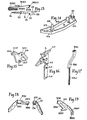
- the slide B is mounted on frame A by means of frame guide rails A9 engaging with slide groove B8 and frame wings A2 act upon and and compress recoil springs carried longitudinally in the slide.
- the rear of the slide holds a breech insert F which is retained by the rear sight N.
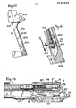
- the breech insert holds the firing pin S, striker GG, and the firing pin spring MM, the striker being prevented from escaping to the rear by its rear face GG1 seating against a solid surface B3 within the rear section of the slide, and the firing pin wing S1 also seats against surface B3 when the firing pin is fully rearwards.
- the firing pin spring will tend to force both the striker and firing pin to the rear equally or independently.
- the wing S4 With the firing pin-fully rearwards the wing S4 will be forced down into the slide cutout B14, and the forward wing surface S3 will abutt against slide cutout vertical transverse surface B15, the firing pin thereby being prevented from being able to move forwards or rearwards.
- the striker lug GG4 While the firing pin is held down by the limb MM4 the striker lug GG4 will ride over the top of the firing pin at the rear, over surface S7, and will act as a safety feature, keeping the firing pin rear down in the slide cutout when the striker is held forward by the hammer, as in Figures 1 and 2.
- the firing pin can only rise out of its locked condition as previously described when the hammer is withdrawn from contact with the striker; thus in the normal rest position of the lockwork, with the hammer down the firing pin cannot possibly contact the primer of a chambered cartridge.
- FIG. 44, 45, and 46 An alternative firing pin and firing pin striker spring is shown in Figures 44, 45, and 46, where the rear coil MM5 of the spring MM is extended to form a limb MM6 which seats partially on surface S3 of the firing pin and which lies on end MM7 which seats against the upper surface of the breech insert hole F6 to maintain level MMB under torsion so that the firing pin is forced down by its engagement by the forward portion of limb M M 6.
- the forward frame accommodates a trigger guard D which is normally kept forced to the rear by trigger guard spring AA and the trigger guard locates against frame pin A19.
- the trigger guard has a cutout section D9 which carries in each side panel a hole D10, into which the trigger pin DD passes transversely from either side, passing through trigger hole G2.
- the trigger G Carried on the trigger pin is the trigger G which has a transverse pin G1 which protrudes from either side of the trigger upper section, onto which are sprung the two formed wings H1 of the trigger bar H.
- Two limbs H2 and H3 of the trigger bar pass longitudinally to the rear inside the frame sides and pass across the magazine well A1.
- the magazine T has its upper portion narrow enough to allow the trigger bar limbs to traverse forwards and backwards and perform all their functions during normal double and single action cycles, and to allow the whole trigger bar to be depressed for disconnection.
- the trigger bar limbs pass rearwardly into the rear frame recess A18 where the limbs are connected transversely by trigger bar rear limb H4.
- the rear upper frame is perforated transversely by the hammer axis pin hole A11, the sear axis pin hole A12, and the manual safety unit arbor axis hole A14.
- the manual safety arbor axis hole has a slot A5 cut parallel to the axis of the rearmost point of the circumference.
- the frame-at either end of hole A12 is reduced in width from that of the regular frame and steps formed on either side inside the grip SS fit adjacent to the ends of the sear axis pin and retain that pin when the grip is fitted to the frame. The whole lockwork is fitted before the grip is fitted.
- the right safety lever unit HH is inserted into the safety axis hole from the right side of the frame with the safety catch spring KK engaged by tongue KK1 with the right safety lever unit arbor peripheral groove HH1 and the safety spring leaf tongue KK3 resting on the right safety lever arbor bridge upper surface.
- the main vertical transverse body of the safety spring will be accommodated in frame slot A5.
- the right safety lever is turned to a vertical position and the left safety lever unit JJ can be inserted into the safety arbor axis hole, the safety spring tongue KK2 can be deflected rearwards to pass along flat JJ3 to reach the left safety lever peripheral groove JJ2, and the right safety lever unit arbor tongue HH3 will mate with the left safety lever unit slot JJ4.
- the whole safety lever unit can be rotated, the levers to point forwards, and the safety spring tongue KK4 will be engaged in the peripheral groove JJ1, and sit in one of two detent notches cut in the groove JJ1, the spring tongue KK4 will seat in the other detent notch when the safety levers are in the position as shown in Figure 27.
- the hammer J, the lifter LL, and ejector L are offered into the frame rear and the hammer axis pin EE is entered through frame hole All, passing through from the right side, ejector hole L1, hammer pivot hole J1, and lifter pivot hole LL1.
- the sear K is offered into the frame rear and the sear axis pin FF is entered through frame hole A12, passing through from the right side, ejector pivot hole L2, and sear pivot hole K1.
- the sear pin K2 will be engaged in ejector hole L3 and in lifter cutout LL2.
- the mainspring strut BB cutout BB1 is engaged with hammer pin J2, the mainspring ZA is mounted on the lower round section BB2 of the mainspring strut and the bottom of section BB2 is entered into hole ZB1 in the mainspring compression unit ZB.
- the mainspring compression unit is fixed to the frame backstrap A20 as shown in Figure 21, permanently, or in a removable manner, the threaded unit hole ZB2 in line with frame backstrap hole A19, which is a clearance hole for the threaded portion of the grip screw TT to pass through when the grip is fitted on the frame.
- FIG 39 shows the pistol with a solid backstrap A28 which has a cut out section A32 traversing down inside the front of the backstrap from the hollow section in the upper rear of the frame where the hammer, sear, ejector and lifter are located.
- the hammer strut passes down inside section A32 carrying on its lower part BB2 the hammer mainspring ZA.
- a slot A31 is cut into both side walls of the backstrap, the slots being parallel to the upper surface of the frame and having their rear extremities rounded to a diameter equal to the height of the slots.
- a hammer mainspring compression block ZC has a vertical hole ZCI through it and a trunnion on two opposite sides. The trunnions have a reduced diameter ZC2 at the outer end, and the inner part of each trunnion ZC3 is of a larger diameter than ZC2.
- An alternative sear and ejector spring ZD is provided and has coils ZD1 that are fitted onto the block trunnions on sections ZC3.
- the hammer mainspring strut section BB2 lower part is put through block hole ZC1 and with compression of the hammer mainspring with block ZC the trunnion outer sections ZC2 can be fitted into the backstrap slots A31.
- the spring ZD arms ZD4 will rest against the rear surface of section A32 and spring arms ZD2 and ZD3 can be engaged respectively with the ejector and the sear.
- the arrow 'A' shows the direction of force exerted on the block ZC by the hammer mainspring
- arrow 'B' shows the direction the trunnions ZC2 will tend to move in under such a force, the angle as shown at 'C' being less than 90°.
- the enlarged inner diameter of the block trunnions will prevent the lateral movement of the block.
- the hammer pin J2 will rotate down and forward around the axis of hammer pin EE, and will force the hammer strut upper section BB3 down and forward also.
- the m a inspring strut lower part will move through the hole ZC1 in the block as the.strut moves down and any tendency for the strut lower portion to pivot will be accommodated for by the ability of the block ZC to rotate on its trunnions in slots A31 rear rounded surfaces.
- a threaded hole A30 is placed in each side wall of the solid backstrap and each grip panel can be secured to the frame with a screw ZE each side.
- the whole firing lock assembled and the pistol complete it is as shown in Figure 1 with the firing lock at rest.
- the trigger and trigger bar are kept forced to the rear by the action of the spring tail Z1 of the hold open spring Z.
- the whole hold open assembly is shown in Figure 22.
- the hold open lever X is held in the frame by axis pin X3 locating in frame hole A4 and pin X1 passing through hole A5.
- the inner hold open member Y fits onto the hold open pins on the inside of the frame, the flange Y1 to the front of the frame.
- the hold open spring coiled section is fitted over the rebate X2 on pin X3, acting to retain both hold open units together; the right angled tail Z2 is seated underneath the forward section of the inner hold open member, as in Figure 7, with the spring tail Z1 bearing against the bottom forward edge H5 of the left forward transverse arm H6 of the trigger bar.
- the pressure of the spring tail Z1 against point H 5 will tend to pivot the trigger bar around the axis of trigger pin G1, thereby forcing the rear of the trigger bar upwards, bearing the disconnector bar tip H8 up against the under surface of the rear slide, and acting as a trigger bar and trigger return spring.
- the trigger is pressed rearwards, drawing the trigger bar forward until the forward face of the trigger bar rear limb contacts hammer bent J4, and will tend to rotate the hammer around its axis pin.
- the hammer will continue to rotate until the forward face of the trigger bar limb contacts the lifter point LL3, and will then rotate the lifter in unison with the hammer.
- Under rotation the lifter will engage its cam LL4 with firing pin wing base S4, and while the pressure is still applied to the trigger the hammer and lifter will continue to rotate, and the lifter cam will elevate the rear of the firing pin.
- the hammer is manually cocked to the position as shown in Figure 3, where the sear nose is engaged in hammer bent J5, the trigger bar rear limb is held rearward against hammer surface J6 and the lifter point LL3 is against the forward surface of the trigger bar rear limb.
- the firing pin wing is locked down into the slide cutout under pressure of the firing pin spring torsion limb MM4, and the lifter cam is positioned under the firing pin wing. It will be seen in Figure 4 that there is clearance between lifter surface LL5 and the sear pin.
- the trigger bar disconnector limb H9 point H8 will be cammed down out of the slide recess B16 by cam surface B17, thereby depressing the rear of the trigger bar out of contact with the lifter point LL3.
- the forward surface LL5 of the lifter cam will impinge on slide cutout forward surface B15 and the lifter cam will be rotated down, the lifter surface LL5 away from the sear pin, and allow the sear nose to move into contact with the hammer forward surface under pressure of the sear and ejector spring BA, the spring arm BA1 acting on the sear tail K6 through the right angle tail BA2.
- the sear and ejector spring locates against the frame backstrap A20, the transverse spring limb BA3 passing through the mainspring compression unit under the unit top plate ZB3, and each spring limb will seat in the notches ZB4 ZB5, the longer sear spring arm BA1 in the left notch ZB4, the shorter limb BA4 will act upon the ejector, the right angle tail BA5 being inserted in ejector hole L4.
- the extracted cartridge case will impinge on ejector point L5 and the case will be ejected from the pistol.
- the slide will return from full recoil position and feed the next cartridge ZA from the magazine into the chamber C1 of the barrel C.
- the trigger bar rear limb will be depressed under the lifter point LL3, and releasing pressure on the trigger will allow the trigger bar to travel rearward and pressure from spring tail Z1, tending to rotate the trigger bar around trigger pin G1 will lift the trigger bar rear limb upwards, placing it behind lifter point LL3.
- the pistol is now ready to fire again in the single action sequence.
- FIG 27 shows the left safety in the applied position, with the hammer in either the cocked or uncocked position.
- the safety bridge HH2 will rotate under the base J6 of the hammer tail, thereby preventing the hammer from moving.
- the forward edge of the safety bridge will impinge on the lifter tail LL7 and rotate the lifter tail upwards, depressing the lifter foward section, and the cutout LL2 will descend as shown in Figure 29 to lock against the sear pin, thereby preventing movement of the sear.
Landscapes
- Engineering & Computer Science (AREA)
- General Engineering & Computer Science (AREA)
- Portable Nailing Machines And Staplers (AREA)
- Percussive Tools And Related Accessories (AREA)
Applications Claiming Priority (2)
| Application Number | Priority Date | Filing Date | Title |
|---|---|---|---|
| GB8502810 | 1985-02-04 | ||
| GB8502810 | 1985-02-04 |
Publications (2)
| Publication Number | Publication Date |
|---|---|
| EP0192343A2 true EP0192343A2 (de) | 1986-08-27 |
| EP0192343A3 EP0192343A3 (de) | 1987-05-20 |
Family
ID=10573918
Family Applications (1)
| Application Number | Title | Priority Date | Filing Date |
|---|---|---|---|
| EP86300466A Withdrawn EP0192343A3 (de) | 1985-02-04 | 1986-01-23 | Abzugsmechanismussicherung für eine halbautomatische Feuerwaffe |
Country Status (2)
| Country | Link |
|---|---|
| EP (1) | EP0192343A3 (de) |
| ZA (1) | ZA86623B (de) |
Cited By (6)
| Publication number | Priority date | Publication date | Assignee | Title |
|---|---|---|---|---|
| WO1988008509A1 (en) * | 1987-04-22 | 1988-11-03 | Bent Agner | A firing mechanism for a semi-automatic arm |
| US5212327A (en) * | 1992-01-07 | 1993-05-18 | Schuemann Wilfred C | Ambidextrous thumb safety |
| US5570527A (en) * | 1995-02-17 | 1996-11-05 | Felicci; Joseph E. | Semi-automatic pistol with a dual safety |
| WO1999049272A1 (de) * | 1998-03-24 | 1999-09-30 | Heckler & Koch Gmbh | Schlagbolzensteuerung |
| US20190033028A1 (en) * | 2017-07-26 | 2019-01-31 | Apex Tactical Specialties, Inc. | Trigger bar for a firearm |
| US10948262B2 (en) | 2018-08-23 | 2021-03-16 | Smith & Wesson Inc. | Firearm and grip strap |
Family Cites Families (5)
| Publication number | Priority date | Publication date | Assignee | Title |
|---|---|---|---|---|
| US2098562A (en) * | 1935-10-17 | 1937-11-09 | J M & M S Browning Company | Firearm |
| CH338381A (de) * | 1955-03-30 | 1959-05-15 | Metallgesellschaft Etablisseme | Schlagbolzenverriegelung an einer Handfeuerwaffe |
| DE2362464C3 (de) * | 1973-12-15 | 1978-03-30 | Fa. Carl Walther, 7900 Ulm | Schlagbolzensicherungseinrichtung für Handfeuerwaffen |
| DE2855224C2 (de) * | 1978-12-21 | 1985-08-08 | Carl Walther Gmbh, 7900 Ulm | Schlagbolzensicherung für Handfeuerwaffen, insbesondere Selbstladepistolen |
| EP0057733A1 (de) * | 1981-02-05 | 1982-08-18 | Llama Gabilondo y Cia. S.A. | Halbautomatische Feuerwaffe |
-
1986
- 1986-01-23 EP EP86300466A patent/EP0192343A3/de not_active Withdrawn
- 1986-01-28 ZA ZA86623A patent/ZA86623B/xx unknown
Cited By (8)
| Publication number | Priority date | Publication date | Assignee | Title |
|---|---|---|---|---|
| WO1988008509A1 (en) * | 1987-04-22 | 1988-11-03 | Bent Agner | A firing mechanism for a semi-automatic arm |
| US5212327A (en) * | 1992-01-07 | 1993-05-18 | Schuemann Wilfred C | Ambidextrous thumb safety |
| US5570527A (en) * | 1995-02-17 | 1996-11-05 | Felicci; Joseph E. | Semi-automatic pistol with a dual safety |
| WO1999049272A1 (de) * | 1998-03-24 | 1999-09-30 | Heckler & Koch Gmbh | Schlagbolzensteuerung |
| US6349495B1 (en) | 1998-03-24 | 2002-02-26 | Heckler & Koch Gmbh | Firing pin control device for a firearm |
| US20190033028A1 (en) * | 2017-07-26 | 2019-01-31 | Apex Tactical Specialties, Inc. | Trigger bar for a firearm |
| US10663245B2 (en) * | 2017-07-26 | 2020-05-26 | Apex Tactical Specialties, Inc. | Trigger bar for a firearm |
| US10948262B2 (en) | 2018-08-23 | 2021-03-16 | Smith & Wesson Inc. | Firearm and grip strap |
Also Published As
| Publication number | Publication date |
|---|---|
| ZA86623B (en) | 1986-09-24 |
| EP0192343A3 (de) | 1987-05-20 |
Similar Documents
| Publication | Publication Date | Title |
|---|---|---|
| US4589327A (en) | Firing lock with safety system for self loading fire arms | |
| US6481145B2 (en) | Grenade launcher | |
| EP3397916B1 (de) | Abfeuerungskontrollsystem für schusswaffe | |
| AU661103B2 (en) | A magazine for a firearm | |
| US11859930B2 (en) | Trigger unit for a firearm | |
| US7827720B1 (en) | Autoloading handgun | |
| US4428138A (en) | Double-action trigger mechanism with trigger-blocking magazine safety for firearms | |
| US4680884A (en) | Safety firearm mechanism | |
| US11578939B2 (en) | Safety mechanism for firearms | |
| US10180296B2 (en) | Firearm adapted to use linked ammunition and kit for converting magazine-fed firearm to same | |
| US11841200B2 (en) | Single-action trigger | |
| NO802628L (no) | Anordning ved haandvaapen. | |
| EP1586850B1 (de) | Pistole mit entferntes-Magazin-Sicherheit | |
| US4052926A (en) | Charging handle for a gas-operated shotgun | |
| US6345463B1 (en) | Extended dust cover for a handgun | |
| US4163334A (en) | Firearm shell extractor | |
| US20110265639A1 (en) | Firearm | |
| EP0192343A2 (de) | Abzugsmechanismussicherung für eine halbautomatische Feuerwaffe | |
| US580924A (en) | Firearm | |
| US11920882B2 (en) | Trigger assembly for a firearm | |
| US4103586A (en) | Firearm trigger mechanism | |
| US4744166A (en) | Firing mechanism with integrated safety device for firearms | |
| GB2137324A (en) | Firing lock with safety system for self-loading firearms | |
| US11808542B2 (en) | Extended slide stop | |
| US11067349B2 (en) | Semi-automatic shotgun with bottom ejecting port |
Legal Events
| Date | Code | Title | Description |
|---|---|---|---|
| PUAI | Public reference made under article 153(3) epc to a published international application that has entered the european phase |
Free format text: ORIGINAL CODE: 0009012 |
|
| AK | Designated contracting states |
Kind code of ref document: A2 Designated state(s): AT BE CH DE FR GB IT LI LU NL SE |
|
| PUAL | Search report despatched |
Free format text: ORIGINAL CODE: 0009013 |
|
| AK | Designated contracting states |
Kind code of ref document: A3 Designated state(s): AT BE CH DE FR GB IT LI LU NL SE |
|
| STAA | Information on the status of an ep patent application or granted ep patent |
Free format text: STATUS: THE APPLICATION IS DEEMED TO BE WITHDRAWN |
|
| 18D | Application deemed to be withdrawn |
Effective date: 19871123 |
|
| RIN1 | Information on inventor provided before grant (corrected) |
Inventor name: SMITH, DAVID EDWARD |