EP0192380B1 - Hydraulisch gedämpfte Lagervorrichtung - Google Patents
Hydraulisch gedämpfte Lagervorrichtung Download PDFInfo
- Publication number
- EP0192380B1 EP0192380B1 EP86300803A EP86300803A EP0192380B1 EP 0192380 B1 EP0192380 B1 EP 0192380B1 EP 86300803 A EP86300803 A EP 86300803A EP 86300803 A EP86300803 A EP 86300803A EP 0192380 B1 EP0192380 B1 EP 0192380B1
- Authority
- EP
- European Patent Office
- Prior art keywords
- bush
- housing
- anchor point
- mounting device
- working chamber
- Prior art date
- Legal status (The legal status is an assumption and is not a legal conclusion. Google has not performed a legal analysis and makes no representation as to the accuracy of the status listed.)
- Expired
Links
- 239000012530 fluid Substances 0.000 claims abstract description 25
- 230000006835 compression Effects 0.000 claims description 12
- 238000007906 compression Methods 0.000 claims description 12
- 238000004891 communication Methods 0.000 claims description 5
- 238000004519 manufacturing process Methods 0.000 claims description 5
- 238000013016 damping Methods 0.000 abstract description 14
- 230000000694 effects Effects 0.000 description 7
- 239000000463 material Substances 0.000 description 6
- 238000010521 absorption reaction Methods 0.000 description 2
- 238000010276 construction Methods 0.000 description 2
- 230000015572 biosynthetic process Effects 0.000 description 1
- 230000008602 contraction Effects 0.000 description 1
- 238000006073 displacement reaction Methods 0.000 description 1
- 238000003780 insertion Methods 0.000 description 1
- 230000037431 insertion Effects 0.000 description 1
- 239000002184 metal Substances 0.000 description 1
- 238000000034 method Methods 0.000 description 1
- 238000000465 moulding Methods 0.000 description 1
Images


Classifications
-
- B—PERFORMING OPERATIONS; TRANSPORTING
- B60—VEHICLES IN GENERAL
- B60K—ARRANGEMENT OR MOUNTING OF PROPULSION UNITS OR OF TRANSMISSIONS IN VEHICLES; ARRANGEMENT OR MOUNTING OF PLURAL DIVERSE PRIME-MOVERS IN VEHICLES; AUXILIARY DRIVES FOR VEHICLES; INSTRUMENTATION OR DASHBOARDS FOR VEHICLES; ARRANGEMENTS IN CONNECTION WITH COOLING, AIR INTAKE, GAS EXHAUST OR FUEL SUPPLY OF PROPULSION UNITS IN VEHICLES
- B60K5/00—Arrangement or mounting of internal-combustion or jet-propulsion units
- B60K5/12—Arrangement of engine supports
- B60K5/1241—Link-type support
-
- F—MECHANICAL ENGINEERING; LIGHTING; HEATING; WEAPONS; BLASTING
- F16—ENGINEERING ELEMENTS AND UNITS; GENERAL MEASURES FOR PRODUCING AND MAINTAINING EFFECTIVE FUNCTIONING OF MACHINES OR INSTALLATIONS; THERMAL INSULATION IN GENERAL
- F16C—SHAFTS; FLEXIBLE SHAFTS; ELEMENTS OR CRANKSHAFT MECHANISMS; ROTARY BODIES OTHER THAN GEARING ELEMENTS; BEARINGS
- F16C7/00—Connecting-rods or like links pivoted at both ends; Construction of connecting-rod heads
- F16C7/04—Connecting-rods or like links pivoted at both ends; Construction of connecting-rod heads with elastic intermediate part of fluid cushion
-
- F—MECHANICAL ENGINEERING; LIGHTING; HEATING; WEAPONS; BLASTING
- F16—ENGINEERING ELEMENTS AND UNITS; GENERAL MEASURES FOR PRODUCING AND MAINTAINING EFFECTIVE FUNCTIONING OF MACHINES OR INSTALLATIONS; THERMAL INSULATION IN GENERAL
- F16F—SPRINGS; SHOCK-ABSORBERS; MEANS FOR DAMPING VIBRATION
- F16F13/00—Units comprising springs of the non-fluid type as well as vibration-dampers, shock-absorbers, or fluid springs
- F16F13/04—Units comprising springs of the non-fluid type as well as vibration-dampers, shock-absorbers, or fluid springs comprising both a plastics spring and a damper, e.g. a friction damper
- F16F13/06—Units comprising springs of the non-fluid type as well as vibration-dampers, shock-absorbers, or fluid springs comprising both a plastics spring and a damper, e.g. a friction damper the damper being a fluid damper, e.g. the plastics spring not forming a part of the wall of the fluid chamber of the damper
- F16F13/08—Units comprising springs of the non-fluid type as well as vibration-dampers, shock-absorbers, or fluid springs comprising both a plastics spring and a damper, e.g. a friction damper the damper being a fluid damper, e.g. the plastics spring not forming a part of the wall of the fluid chamber of the damper the plastics spring forming at least a part of the wall of the fluid chamber of the damper
- F16F13/14—Units of the bushing type, i.e. loaded predominantly radially
- F16F13/1409—Units of the bushing type, i.e. loaded predominantly radially characterised by buffering features or stoppers
-
- F—MECHANICAL ENGINEERING; LIGHTING; HEATING; WEAPONS; BLASTING
- F16—ENGINEERING ELEMENTS AND UNITS; GENERAL MEASURES FOR PRODUCING AND MAINTAINING EFFECTIVE FUNCTIONING OF MACHINES OR INSTALLATIONS; THERMAL INSULATION IN GENERAL
- F16F—SPRINGS; SHOCK-ABSORBERS; MEANS FOR DAMPING VIBRATION
- F16F13/00—Units comprising springs of the non-fluid type as well as vibration-dampers, shock-absorbers, or fluid springs
- F16F13/04—Units comprising springs of the non-fluid type as well as vibration-dampers, shock-absorbers, or fluid springs comprising both a plastics spring and a damper, e.g. a friction damper
- F16F13/06—Units comprising springs of the non-fluid type as well as vibration-dampers, shock-absorbers, or fluid springs comprising both a plastics spring and a damper, e.g. a friction damper the damper being a fluid damper, e.g. the plastics spring not forming a part of the wall of the fluid chamber of the damper
- F16F13/08—Units comprising springs of the non-fluid type as well as vibration-dampers, shock-absorbers, or fluid springs comprising both a plastics spring and a damper, e.g. a friction damper the damper being a fluid damper, e.g. the plastics spring not forming a part of the wall of the fluid chamber of the damper the plastics spring forming at least a part of the wall of the fluid chamber of the damper
- F16F13/14—Units of the bushing type, i.e. loaded predominantly radially
- F16F13/149—Multiple bushings connected together; Restraining links
-
- B—PERFORMING OPERATIONS; TRANSPORTING
- B60—VEHICLES IN GENERAL
- B60G—VEHICLE SUSPENSION ARRANGEMENTS
- B60G2204/00—Indexing codes related to suspensions per se or to auxiliary parts
- B60G2204/40—Auxiliary suspension parts; Adjustment of suspensions
- B60G2204/41—Elastic mounts, e.g. bushings
- B60G2204/4104—Bushings having modified rigidity in particular directions
-
- B—PERFORMING OPERATIONS; TRANSPORTING
- B60—VEHICLES IN GENERAL
- B60G—VEHICLE SUSPENSION ARRANGEMENTS
- B60G2206/00—Indexing codes related to the manufacturing of suspensions: constructional features, the materials used, procedures or tools
- B60G2206/01—Constructional features of suspension elements, e.g. arms, dampers, springs
- B60G2206/10—Constructional features of arms
- B60G2206/11—Constructional features of arms the arm being a radius or track or torque or steering rod or stabiliser end link
- B60G2206/111—Constructional features of arms the arm being a radius or track or torque or steering rod or stabiliser end link of adjustable length
- B60G2206/1114—Self-adjustable during driving
Definitions
- the present invention relates to a hydraulically damped mounting device.
- Mounting devices are known from e.g. our European Patent Applications No. 0115417 and 0172700 (prior art Art. 54(3) EPC) having two anchor points connected together by a resilient spring, the resilient spring defining one wall of a working chamber for hydraulic fluid connected by an elongate passageway to another chamber. Relative movement of the anchor points causes a change in the volume of the chamber bounded by the resilient wall. This forces the fluid through the passageway and the viscosity causes damping of the movement.
- Such mounting devices are used, for example, to mount a car engine in the body so that vibration of the engine is damped before it is transmitted to the car body (see e.g. US-A-2705118).
- three or much such mounting devices may be provided to support the engine at separate positions.
- this arrangement for damping the vibration of the engine is unsatisfactory for torsional movement. Since each mounting device is independent, different damping effects may result at different points of the engine and this may accentuate, rather than diminish, torsional movement. This is a particular problem because it is desirablethatthe natural frequency of the mounted system under torsional vibration is high and this may result in the natural frequency being excited by the engine vibration, causing resonance.
- the present invention proposes a mounting device with at least two working chambers interconnected by an elongate passageway and held apart by an elongate rigid member.
- the result is a hydraulically damped tie-rod which may be interconnected between one vibrating body and another (e.g. between an engine and the car body) which resists torsional movement.
- the mounting device has two bushes connected together by a rigid bar or rod.
- Each bush has a resilient spring which connects the bush to an anchor point and which acts as one wall of a working chamber within the bush.
- the working chambers are connected together by an elongate passageway which conveniently may be formed by a bore in the rod.
- Each spring also bounds a further chamber which may be a working chamber filled with hydraulic fluid, which further working chambers are connected by a second passageway.
- This increases the damping force and makes for a more symmetrical construction because each vibration then causes a compression of one of each pair of chambers and an expansion of the other pair.
- the spring attached to anchor point is compressed whilst the other expands. The effect of this may be to create unequal damping.
- the chambers are normally arranged so as to resist forces causing compression or tension in the rod.
- each bush in the form of a hollow unit with the anchor point approximately centrally within the bush and the spring extending from the anchor point to the surrounding walls of the bush, so that the working chamber is bounded by the spring and by a part of the inner wall of the bush.
- the further chamber in the bush may be fitted with air, which is preferably vented to the atmosphere to prevent temperature changes causing a change in characteristics.
- the spring may divide the interior of the bush into two, so that the two chambers fill the bush.
- the damping effect may be adjusted so that the damping is optimised at the resonant frequency of torsional vibrations.
- the resilient spring is preferably made of rubber or similar material. However, such materials should not be under tensile loads. Therefore it is desirable that the resilient spring is pre-compressed during the manufacture of the mount so that it remains under compression during all vibrations.
- a hydraulically damped tie-rod according to a first embodiment of the present invention has two bushes 1, 2 connected by a hollow rod 3, each bush having an anchor point in the form of a central sleeve 4, 5.
- the sleeves 4, are adapted for fixing to those parts that are to be linked by the tie-rod, and are mounted within similar resilient insert springs 6, 7 made of rubber or rubber-type material.
- the insert springs 6, are themselves held tightly within respective tubular housings 8, 9 which in this embodiment are integral with the connecting rod 3.
- the shape of springs 6, 7 is such that they hold sleeves 4, 5 in portions concentric with the respective housings 8, 9 in the absence of deforming forces.
- chambers 10,11,12,13 are defined between surfaces of the springs 6, 7 and the inner surfaces of housing 8 and 9.
- chambers lie on the axis of the tie-rod assembly, so that there are two inner chambers 11, 12 and two outer chambers 10, 13. Movement of one of the sleeves 4, 5 with respect to its housing 8 or 9 therefore causes an increase in volume of one chamber and a decrease in the volume of the other within that housing.
- bushes 1 and 2 are rigidly connected by a hollow rod 3, and this provides communication by means of a bore forming a passageway 14 between the inner chamber 11 of bush 1 and the outer chamber 13 of bush 2. Access to the outer chamber 13 is provided via a curved part 14a of the passageway and rod 3, which passes circumferentially around the outside of the housing 9.
- the closed system thus formed is filled with a hydraulic fluid, so that, for example, pressure on spring 6 tending to reduce the volume of chamber 11 is transmitted via the hydraulic fluid through passageway 14 and thereby tends to increase the volume of chamber 13.
- the movement of the fluid is restricted by the need to increase the volume of chamber 13 and by viscosity effects, so damping the movement.
- the second pair of chambers 10, 12 are neither connected nor filled with hydraulic fluid, but the parts of tubular housings 8, 9 that bound these chambers are provided with sets of holes 15, 16 that allow substantially free passage of atmospheric air in and out of chambers 10 and 12.
- Figures 1,2,3, and 4 make clear the structure of the insert springs 6 and 7. These are enlarged at each end of their tubular housings 8 and 9 so as to completely occupy the area of the housings and thereby close off the chambers 10, 11, 12, 13 at these ends. Because the rubber and rubber-like materials used for springs 6 and 7 are not strong in tension, the springs are initially moulded with a diameter significantly greater than that of housings 8, 9 and subsequently compressed in order to be inserted into the housings. The pre-compression shape of the springs, the provision of semi-circular metal flanges 17, and of seals 18 to prevent leakage of fluid between spring and housing, may be seen in Figures 3 and 4. The springs 6, 7 are first moulded around the sleeves 4, and to the flanges 17.
- the springs 6, together with the sleeve 4, are prevented from sliding out of the housings 8, by the rolled-over edges of the flanges 17 to which the springs are initially moulded.
- the sleeves 4, 5 at the centre of bushes 1, 2 are fixed to the two parts that are to be linked. These might be, for example, an engine and a surrounding part of a vehicle, wherein it is desired to damp torsional vibrations of the mounted system at a resonance frequency excited by the engine vibration. Relative vibration between these two parts will alternately force the two sleeves towards one another and away from one another. When they are forced together, inner chambers 11 and 12 tend to contract, while outer chambers 10 and 13 tend to expand. For these volume changes to take place, hydraulic fluid must pass from chamber 11 via passageway 14 into chamber 13. When the sleeves 4, 5 move apart in the second phase of the vibration, the fluid must pass in the reverse direction. The inertial and viscous resistance of the fluid to moving quickly in this fashion provides the desired damping effect on the vibration.
- the length and cross-sectional area of the passageway 14 can be varied in construction, so as to provide tie-rods giving optimum damping over desired frequency ranges.
- Very high frequency vibrations which are generally of small amplitude, are largely absorbed within the springs 6 and 7.
- a gas pocket may be provided communicating with each chamber as discussed in EP-A-84.300406.0 to improve the absorption of the high frequency vibrations.
- Air in the chambers 10 and 12 is free to pass through holes 15 and 16 during vibration, and this also prevents changes in the behaviour of the tie-rod due to thermal expansion and contraction.
- the second embodiment shown in Figure 5 includes bushes 1, similar to those described for the first embodiment, having central sleeves 4, 5, resilient insert springs 6, 7 and housings 8, 9 with chambers 10, 11, 12, 13 formed within them.
- This second embodiment is generally similar to the first, and so the same reference numerals are used for corresponding parts.
- the bushes 1, are joined by a rod 23, having two passageways 24, 25 defined by bores within it, so that passageway 2 communicates between chambers 10 and 12, while passageway 25 communicates between chambers 11 and 13.
- Access to the outer chambers 10, 13 is provided via curved parts 24a and 25a of the passageways 24, 25 that pass circumferentially around the outside of housings 8 and 9 respectively.
- Both of the two closed systems thus formed are filled with hydraulic fluid; there are no air filled chambers and no vent holes through the housing to allow access to the atmosphere as there were in the first embodiment.
- the second embodiment of the invention works similarly to the invention, except that relative movements of the sleeves 4, 5 cause fluid to pass between chambers 10 and 12 as well as between chambers 11 and 13.
- the damping effect thus produced may be optimised against the range of possible frequencies by selecting the constructional parameters of the communicating passageways 24 and 25.
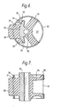
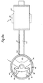
- a bush according to this embodiment uses a generally cylindrical inner housing 30 with apertures 31, 32 at diagonally opposite sides.
- a sleeve 33 forming the anchor point of the bush is also modified, as compared with the sleeves 4, 5 of the first and second embodiments, by the provision of wings 34 on either side of a central part 35.
- a resilient spring 36 of rubber or rubber-type material is formed between the central part 35 of the sleeve 33 and a part of the inner surface of the inner housing 30 to form a space 37 which will subsequently form a working chamber.
- a rubber or rubber-like block 38 is moulded to the sleeve 33 which extends out of the aperture 31, and rubber or rubber-like stops 39 are moulded to the wings 34 and extend to the inner surface of the inner housing 30.
- the stops 39 are not bonded to the inner surface of the inner housing 30, but simply rest on it in the position shown in Figure 6. It can be seen from that figure that when the spring is moulded, the central axis of the sleeve 33 is displaced from the central axis of the inner housing 30, in a direction away from the space 37.
- the block 38 When the inner housing 30 is inserted in the outer housing 40, the block 38 is forced inwards, moving the sleeve 33 so as to compress the spring 36. This gives the pre-compression of the spring necessary to ensurethatthe material of the spring 36 is not put under tension during vibration of the mount.
- the size and shape of the block 38 is determined by the desired pre-compression of the spring 36.
- the stiffness of the block 38 is similar to the stiffness of the spring 36 so that the sleeve 33 moves half the compression applied to the block. In this way it is possible to ensure that the sleeve 33 is moved to the correct position in the housing; in general the sleeve 33 will have a central position in the absence of an external load.
- this embodiment is similar to the first embodiment, in that relative movement of the objects to which the sleeves 33 of the bushes 1, 2 are attached causes compression of one working chamber and expansion of the other. Hydraulic fluid filling the chambers 44, 45 and the passageway 43 moves from the chamber being compressed, through the passageway 43, and to the expanding chamber. The movement of the fluid acts as a damping force on the vibration of the objects connected by the mounting device.
- this third embodiment is easier to manufacture, and is therefore presently preferred.
- the spaces 46, 47 on the opposite side of the spring 36 from the working chambers 44, 45 may be vented to the air in order to prevent thermal changes in the characteristics of the mounting device, and a gas pocket may be provided communicating with the working chambers 44, 45 in order to improve absorption of high frequency vibrations, as discussed earlier.
Landscapes
- Engineering & Computer Science (AREA)
- General Engineering & Computer Science (AREA)
- Mechanical Engineering (AREA)
- Chemical & Material Sciences (AREA)
- Combustion & Propulsion (AREA)
- Transportation (AREA)
- Combined Devices Of Dampers And Springs (AREA)
- Clamps And Clips (AREA)
- Vibration Prevention Devices (AREA)
Claims (10)
Priority Applications (1)
| Application Number | Priority Date | Filing Date | Title |
|---|---|---|---|
| AT86300803T ATE42620T1 (de) | 1985-02-07 | 1986-02-06 | Hydraulisch gedaempfte lagervorrichtung. |
Applications Claiming Priority (2)
| Application Number | Priority Date | Filing Date | Title |
|---|---|---|---|
| GB858503144A GB8503144D0 (en) | 1985-02-07 | 1985-02-07 | Hydraulically damped mounting device |
| GB8503144 | 1985-02-07 |
Publications (2)
| Publication Number | Publication Date |
|---|---|
| EP0192380A1 EP0192380A1 (de) | 1986-08-27 |
| EP0192380B1 true EP0192380B1 (de) | 1989-04-26 |
Family
ID=10574099
Family Applications (1)
| Application Number | Title | Priority Date | Filing Date |
|---|---|---|---|
| EP86300803A Expired EP0192380B1 (de) | 1985-02-07 | 1986-02-06 | Hydraulisch gedämpfte Lagervorrichtung |
Country Status (5)
| Country | Link |
|---|---|
| US (1) | US4697795A (de) |
| EP (1) | EP0192380B1 (de) |
| AT (1) | ATE42620T1 (de) |
| DE (1) | DE3663076D1 (de) |
| GB (1) | GB8503144D0 (de) |
Cited By (1)
| Publication number | Priority date | Publication date | Assignee | Title |
|---|---|---|---|---|
| DE19617992C1 (de) * | 1996-05-04 | 1997-10-30 | Pahl Gummi Asbest | Drehmomentstütze |
Families Citing this family (14)
| Publication number | Priority date | Publication date | Assignee | Title |
|---|---|---|---|---|
| JPH01119950U (de) * | 1988-02-08 | 1989-08-14 | ||
| GB2234317B (en) * | 1989-07-20 | 1993-03-24 | Draftex Ind Ltd | Movement controlling strut |
| US5000428A (en) * | 1989-12-01 | 1991-03-19 | Lord Corporation | Fluid-damped strut |
| FR2736877B1 (fr) * | 1995-07-20 | 1997-09-26 | Hutchinson | Support elastique pour moteur de vehicule |
| FR2766771B1 (fr) * | 1997-07-30 | 1999-10-15 | Hutchinson | Biellette de reprise de couple pour moteur a combustion interne |
| GB2339260A (en) * | 1998-07-08 | 2000-01-19 | Draftex Ind Ltd | Restraining link |
| US6698731B2 (en) * | 2002-04-24 | 2004-03-02 | The Pullman Company | High compliance multiple chamber piston for fluid damped elastomer devices |
| DE10235303A1 (de) * | 2002-08-01 | 2004-02-19 | Woco Avs Gmbh | Radiallager |
| US20040262460A1 (en) * | 2003-06-25 | 2004-12-30 | Pal Molnar | Elastomer hanger for an elastomer suspension |
| JP4589612B2 (ja) | 2003-09-05 | 2010-12-01 | 株式会社ブリヂストン | 防振装置 |
| KR20050038139A (ko) * | 2003-10-21 | 2005-04-27 | 기아자동차주식회사 | 자동차의 로어암 부시 장치 |
| FR2904075A1 (fr) * | 2006-07-19 | 2008-01-25 | Hutchinson Sa | Support antivibratoire hydraulique, manchon interne pour un tel support et procede de fabrication d'un tel support. |
| ES2536686T3 (es) * | 2010-02-08 | 2015-05-27 | Vestas Wind Systems A/S | Elemento elástico, conjunto de suspensión y turbina eólica con el conjunto de suspensión |
| JP6068215B2 (ja) * | 2013-03-20 | 2017-01-25 | 東洋ゴム工業株式会社 | 防振装置 |
Citations (3)
| Publication number | Priority date | Publication date | Assignee | Title |
|---|---|---|---|---|
| US2705118A (en) * | 1952-01-30 | 1955-03-29 | Lord Mfg Co | Mounting system |
| EP0115417A2 (de) * | 1983-01-25 | 1984-08-08 | Avon Industrial Polymers Limited | Hydraulisch gedämpfte Lagerungsvorrichtung |
| EP0172700A1 (de) * | 1984-08-07 | 1986-02-26 | Avon Industrial Polymers Limited | Hydraulisch gedämpftes Lager |
Family Cites Families (8)
| Publication number | Priority date | Publication date | Assignee | Title |
|---|---|---|---|---|
| US1823694A (en) * | 1927-11-17 | 1931-09-15 | Packard Motor Car Co | Motor vehicle |
| DE577404C (de) * | 1930-11-13 | 1934-07-05 | Fritz Albert Deutsch Dipl Ing | Vorrichtung zur Stossdaempfung eines Fahrzeugs |
| BE375752A (de) * | 1930-12-15 | |||
| FR2364373A1 (fr) * | 1976-09-09 | 1978-04-07 | Peugeot | Dispositif de suspension pour machine tournante |
| GB1568178A (en) * | 1978-02-22 | 1980-05-29 | Gen Electric Co Ltd | Optical fibre cables |
| JPS5643028A (en) * | 1979-09-18 | 1981-04-21 | Nissan Motor Co Ltd | Low noise vehicle |
| CA1226230A (en) * | 1983-11-23 | 1987-09-01 | Richard A. Muzechuk | Hydraulic-elastomeric mount |
| US4611782A (en) * | 1984-06-08 | 1986-09-16 | Bridgestone Corporation | Vibration isolating apparatus |
-
1985
- 1985-02-07 GB GB858503144A patent/GB8503144D0/en active Pending
-
1986
- 1986-02-06 DE DE8686300803T patent/DE3663076D1/de not_active Expired
- 1986-02-06 US US06/826,858 patent/US4697795A/en not_active Expired - Lifetime
- 1986-02-06 AT AT86300803T patent/ATE42620T1/de not_active IP Right Cessation
- 1986-02-06 EP EP86300803A patent/EP0192380B1/de not_active Expired
Patent Citations (3)
| Publication number | Priority date | Publication date | Assignee | Title |
|---|---|---|---|---|
| US2705118A (en) * | 1952-01-30 | 1955-03-29 | Lord Mfg Co | Mounting system |
| EP0115417A2 (de) * | 1983-01-25 | 1984-08-08 | Avon Industrial Polymers Limited | Hydraulisch gedämpfte Lagerungsvorrichtung |
| EP0172700A1 (de) * | 1984-08-07 | 1986-02-26 | Avon Industrial Polymers Limited | Hydraulisch gedämpftes Lager |
Cited By (1)
| Publication number | Priority date | Publication date | Assignee | Title |
|---|---|---|---|---|
| DE19617992C1 (de) * | 1996-05-04 | 1997-10-30 | Pahl Gummi Asbest | Drehmomentstütze |
Also Published As
| Publication number | Publication date |
|---|---|
| DE3663076D1 (en) | 1989-06-01 |
| GB8503144D0 (en) | 1985-03-13 |
| EP0192380A1 (de) | 1986-08-27 |
| ATE42620T1 (de) | 1989-05-15 |
| US4697795A (en) | 1987-10-06 |
Similar Documents
| Publication | Publication Date | Title |
|---|---|---|
| EP0192380B1 (de) | Hydraulisch gedämpfte Lagervorrichtung | |
| US4690389A (en) | Hydraulically damped mounting device | |
| EP0406835B1 (de) | Verfahren zum Herstellen von elastischen, flüssigkeitsgefüllten Lagern mit Druckaufnahme- und Ausgleichskammern | |
| US4786036A (en) | Resilient bushing structure filled with viscous fluid | |
| US6419215B1 (en) | Bi-component bushing | |
| CA2010918A1 (en) | Rubber brushing | |
| JPH01283444A (ja) | 弾性サポート | |
| US4899997A (en) | Fluid filled resilient bushing | |
| US4974819A (en) | Mount for controlling or isolating vibration | |
| RU2256588C2 (ru) | Демпфер вибраций, предназначенный, в частности, для несущего винта вертолета | |
| US4919401A (en) | Fluid-filled bushing having radially displaceable intermediate sleeve coated with sealing rubber layer | |
| US4893798A (en) | Fluid-filled elastic bushing having means for limiting elastic deformation of axial end portions of elastic member defining pressure-receiving chamber | |
| US7806420B2 (en) | Hydraulic damper | |
| US4964623A (en) | Fluid filled resilient bushing | |
| JPH025937B2 (de) | ||
| US4566677A (en) | Vibration damper and in particular frequency adapter for a helicopter blade | |
| WO1998048196A1 (en) | Pneumatic damping strut | |
| US4854561A (en) | Elastic bushing filled with viscous fluid | |
| EP0623197B1 (de) | Elasto-hydraulischer schwingungsisolator | |
| EP1571369B1 (de) | Flüssigkeits- und Elastomereinrichtung mit diskretem Volumenkompensator und sekündärem Angleichselement | |
| GB2322427A (en) | Hydraulically damped mounting device | |
| GB2351138A (en) | Mounting device for hydraulically damping both axial and radial vibrations | |
| JPH01116329A (ja) | 防振装置 | |
| JPS62118132A (ja) | 液入り防振装置 | |
| JPH0726664B2 (ja) | 流体封入型ブツシユ |
Legal Events
| Date | Code | Title | Description |
|---|---|---|---|
| PUAI | Public reference made under article 153(3) epc to a published international application that has entered the european phase |
Free format text: ORIGINAL CODE: 0009012 |
|
| AK | Designated contracting states |
Kind code of ref document: A1 Designated state(s): AT BE CH DE FR GB IT LI LU NL SE |
|
| 17P | Request for examination filed |
Effective date: 19870204 |
|
| 17Q | First examination report despatched |
Effective date: 19880422 |
|
| GRAA | (expected) grant |
Free format text: ORIGINAL CODE: 0009210 |
|
| AK | Designated contracting states |
Kind code of ref document: B1 Designated state(s): AT BE CH DE FR GB IT LI LU NL SE |
|
| PG25 | Lapsed in a contracting state [announced via postgrant information from national office to epo] |
Ref country code: IT Free format text: LAPSE BECAUSE OF FAILURE TO SUBMIT A TRANSLATION OF THE DESCRIPTION OR TO PAY THE FEE WITHIN THE PRESCRIBED TIME-LIMIT;WARNING: LAPSES OF ITALIAN PATENTS WITH EFFECTIVE DATE BEFORE 2007 MAY HAVE OCCURRED AT ANY TIME BEFORE 2007. THE CORRECT EFFECTIVE DATE MAY BE DIFFERENT FROM THE ONE RECORDED. Effective date: 19890426 Ref country code: CH Effective date: 19890426 Ref country code: AT Effective date: 19890426 Ref country code: BE Effective date: 19890426 Ref country code: LI Effective date: 19890426 Ref country code: NL Effective date: 19890426 |
|
| REF | Corresponds to: |
Ref document number: 42620 Country of ref document: AT Date of ref document: 19890515 Kind code of ref document: T |
|
| REF | Corresponds to: |
Ref document number: 3663076 Country of ref document: DE Date of ref document: 19890601 |
|
| ET | Fr: translation filed | ||
| REG | Reference to a national code |
Ref country code: CH Ref legal event code: PL |
|
| NLV1 | Nl: lapsed or annulled due to failure to fulfill the requirements of art. 29p and 29m of the patents act | ||
| PGFP | Annual fee paid to national office [announced via postgrant information from national office to epo] |
Ref country code: FR Payment date: 19900219 Year of fee payment: 5 |
|
| PGFP | Annual fee paid to national office [announced via postgrant information from national office to epo] |
Ref country code: SE Payment date: 19900221 Year of fee payment: 5 |
|
| PLBE | No opposition filed within time limit |
Free format text: ORIGINAL CODE: 0009261 |
|
| STAA | Information on the status of an ep patent application or granted ep patent |
Free format text: STATUS: NO OPPOSITION FILED WITHIN TIME LIMIT |
|
| PG25 | Lapsed in a contracting state [announced via postgrant information from national office to epo] |
Ref country code: LU Free format text: LAPSE BECAUSE OF NON-PAYMENT OF DUE FEES Effective date: 19900228 |
|
| 26N | No opposition filed | ||
| PG25 | Lapsed in a contracting state [announced via postgrant information from national office to epo] |
Ref country code: SE Effective date: 19910207 |
|
| PG25 | Lapsed in a contracting state [announced via postgrant information from national office to epo] |
Ref country code: FR Effective date: 19911031 |
|
| REG | Reference to a national code |
Ref country code: FR Ref legal event code: ST |
|
| EUG | Se: european patent has lapsed |
Ref document number: 86300803.3 Effective date: 19911008 |
|
| PGFP | Annual fee paid to national office [announced via postgrant information from national office to epo] |
Ref country code: GB Payment date: 20010126 Year of fee payment: 16 |
|
| PGFP | Annual fee paid to national office [announced via postgrant information from national office to epo] |
Ref country code: DE Payment date: 20010220 Year of fee payment: 16 |
|
| REG | Reference to a national code |
Ref country code: GB Ref legal event code: IF02 |
|
| PG25 | Lapsed in a contracting state [announced via postgrant information from national office to epo] |
Ref country code: GB Free format text: LAPSE BECAUSE OF NON-PAYMENT OF DUE FEES Effective date: 20020206 |
|
| PG25 | Lapsed in a contracting state [announced via postgrant information from national office to epo] |
Ref country code: DE Free format text: LAPSE BECAUSE OF NON-PAYMENT OF DUE FEES Effective date: 20020903 |
|
| GBPC | Gb: european patent ceased through non-payment of renewal fee |
Effective date: 20020206 |