EP0192387B1 - Castor wheel and method of manufacture - Google Patents
Castor wheel and method of manufacture Download PDFInfo
- Publication number
- EP0192387B1 EP0192387B1 EP86300851A EP86300851A EP0192387B1 EP 0192387 B1 EP0192387 B1 EP 0192387B1 EP 86300851 A EP86300851 A EP 86300851A EP 86300851 A EP86300851 A EP 86300851A EP 0192387 B1 EP0192387 B1 EP 0192387B1
- Authority
- EP
- European Patent Office
- Prior art keywords
- bore
- spindle
- rib
- article
- ribs
- Prior art date
- Legal status (The legal status is an assumption and is not a legal conclusion. Google has not performed a legal analysis and makes no representation as to the accuracy of the status listed.)
- Expired
Links
Images


Classifications
-
- B—PERFORMING OPERATIONS; TRANSPORTING
- B60—VEHICLES IN GENERAL
- B60B—VEHICLE WHEELS; CASTORS; AXLES FOR WHEELS OR CASTORS; INCREASING WHEEL ADHESION
- B60B33/00—Castors in general ; Anti-clogging castors
- B60B33/0028—Construction of wheels; methods of assembling on axle
-
- Y—GENERAL TAGGING OF NEW TECHNOLOGICAL DEVELOPMENTS; GENERAL TAGGING OF CROSS-SECTIONAL TECHNOLOGIES SPANNING OVER SEVERAL SECTIONS OF THE IPC; TECHNICAL SUBJECTS COVERED BY FORMER USPC CROSS-REFERENCE ART COLLECTIONS [XRACs] AND DIGESTS
- Y10—TECHNICAL SUBJECTS COVERED BY FORMER USPC
- Y10S—TECHNICAL SUBJECTS COVERED BY FORMER USPC CROSS-REFERENCE ART COLLECTIONS [XRACs] AND DIGESTS
- Y10S16/00—Miscellaneous hardware, e.g. bushing, carpet fastener, caster, door closer, panel hanger, attachable or adjunct handle, hinge, window sash balance
- Y10S16/27—Bearings
Definitions
- the present invention is concerned with a moulded plastics article such as a wheel for a castor which is adapted to be mounted for rotation on a spindle or axle and with a method of manufacture thereof and with a method of attaching the article to a spindle.
- a moulded plastics article such as a castor wheel with a closed bore to receive a spindle, the bore being formed with at least one radially inwardly projecting circumferentially extending annular rib adapted to locate in a respective circumferential groove in the spindle, the or each rib is being interrupted to leave a single gap in the circumferential extent thereof for the passage of fluid from one side of the rib to the other when the spindle is inserted into the bore.
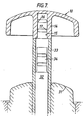
- a moulded plastics castor wheel is indicated generally at 10 which is adapted to be mounted on and end of a steel spindle or axle 11.
- the wheel 10 comprises an outer wall 12 which is outwardly convex, a circumferential flange 13 which forms the rolling surface of the wheel and an internal tubular boss 14.
- the boss 14 defines a closed bore 15 which is adapted to receive the spindle 11.
- the bore 15 is formed with two similar radially inwardly projecting circumferentially extending annular ribs 16 and 17 which are spaced axially along the bore.
- the ribs 16 and 17 are interrupted to leave single gaps 18 and 19, respectively, on their circumferential extents so positioned that they are angularly displaced by approximately 180°.
- the spindle 11 is formed with a chamfered end 20 to facilitate insertion of the spindle into the bore 15 and past the ribs 16 and 17 and with two circumferential grooves 21 and 22 which are respectively adapted to receive the ribs 16 and 17 when the spindle is inserted fully home into the bore 15.
- each circumferential groove 21, 22 has opposed annular sloping side walls, the axially outer side wall of each groove sloping to a lesser extent than the axially inner side wall thereof.
- the spindle is pressed into the bore 15.
- the spindle is a close fit within the bore so that the ribs 16 and 17 are compressed by the spindle and then spring back into the grooves 21 and 22, respectively, to retain the wheel securely on the end of the spindle while allowing free rotation of the wheel relative to the spindle.
- fluid in the form of air or any liquid in the bore can pass between the rib and the spindle through the gaps 18 and 19 so that there is no build up of pressure in front of the leading end of the spindle. This ensures that the spindle can be relatively easily inserted into the bore without any risk of the ribs being damaged or the wall 12 in the area of the end of the bore being fractured or distorted.
- the castor wheel 10 is moulded in a die comprising die plates 30 and 31 which form the mould cavity, a core 32 slidably mounted in a sleeve 33 and a spigot 34 on the end of the core 32 which forms the bore 15 in the tubular boss 14 of the castor wheel.
- the bore may be provided with only one rib or with a plurality of ribs, for instance three, four or five ribs. If only one rib is provided in the bore it may be necessary, in order to ensure sufficient retention, for the rib to be relatively larger.
- the method of manufacture described herein is particularly advantageous because it facilitates withdrawal of the core from the bore during the moulding process, even if the rib is relatively larger and protrudes significantly into the bore.
- a plurality of ribs are provided, that is two or more, then it is preferable to ensure that the gaps are sequentially and equi-angularly spaced around the axis of the bore to facilitate the spread of grease around the spindle as the spindle is inserted into the bore. For. instance if three sets are provided the gaps will be spaced at 120° intervals around the axis and if there are four ribs they will be spaced by 90° around the axis.
- the castor wheel disclosed herein can be manufactured from any suitable synthetic plastics material such as nylon or polypropylene and the spindle or axle is preferably formed from steel but may be made from any other suitable material having the required characteristics.
Landscapes
- Engineering & Computer Science (AREA)
- Mechanical Engineering (AREA)
- Moulds For Moulding Plastics Or The Like (AREA)
- Pens And Brushes (AREA)
- Prostheses (AREA)
- Axle Suspensions And Sidecars For Cycles (AREA)
- Rolls And Other Rotary Bodies (AREA)
Applications Claiming Priority (2)
| Application Number | Priority Date | Filing Date | Title |
|---|---|---|---|
| GB8503511 | 1985-02-12 | ||
| GB08503511A GB2171897B (en) | 1985-02-12 | 1985-02-12 | Castor wheel |
Publications (3)
| Publication Number | Publication Date |
|---|---|
| EP0192387A2 EP0192387A2 (en) | 1986-08-27 |
| EP0192387A3 EP0192387A3 (en) | 1987-12-16 |
| EP0192387B1 true EP0192387B1 (en) | 1989-06-28 |
Family
ID=10574309
Family Applications (1)
| Application Number | Title | Priority Date | Filing Date |
|---|---|---|---|
| EP86300851A Expired EP0192387B1 (en) | 1985-02-12 | 1986-02-07 | Castor wheel and method of manufacture |
Country Status (6)
| Country | Link |
|---|---|
| US (1) | US4731901A (da) |
| EP (1) | EP0192387B1 (da) |
| DE (1) | DE3664119D1 (da) |
| DK (1) | DK162434C (da) |
| GB (1) | GB2171897B (da) |
| NO (1) | NO162849C (da) |
Families Citing this family (19)
| Publication number | Priority date | Publication date | Assignee | Title |
|---|---|---|---|---|
| US4806024A (en) * | 1986-10-31 | 1989-02-21 | Tanashin Denki Co., Ltd. | Rotatably supporting structure |
| GB2197427B (en) * | 1986-11-03 | 1990-09-26 | Tanashin Denki Co | Bearing assembly |
| GB8905404D0 (en) * | 1989-03-09 | 1989-04-19 | Guy Raymond Eng Co Ltd | Castor |
| EP0386956B1 (en) * | 1989-03-09 | 1994-06-01 | Guy-Raymond Engineering Company Limited | Castors |
| FR2659419B1 (fr) * | 1990-03-06 | 1992-09-04 | Villemin Michel | Dispositif de graissage pour roulettes. |
| US5136751A (en) * | 1991-04-30 | 1992-08-11 | Master Manufacturing Co. | Wheel assembly |
| US5375514A (en) * | 1993-06-07 | 1994-12-27 | Dann, Jr.; Herbert I. | Adjustable height table support mechanism |
| USD426495S (en) * | 1999-05-12 | 2000-06-13 | Vaccaro Tim J | Attachable slide disk |
| GB2372550B (en) * | 2000-10-10 | 2005-01-12 | Borgwarner Inc | Valve plate and shaft connection |
| US6550100B2 (en) | 2001-02-08 | 2003-04-22 | Waxman Industries, Inc. | Caster assembly with multi-position support pieces |
| US6728991B2 (en) | 2002-04-15 | 2004-05-04 | Waxman Industries, Inc. | Caster assembly with sliding side support piece |
| US7404232B2 (en) * | 2004-09-15 | 2008-07-29 | John Chase | Furniture glide assembly |
| US20070204430A1 (en) * | 2004-09-15 | 2007-09-06 | John Chase | Furniture-glide assembly |
| US7234200B2 (en) * | 2004-09-15 | 2007-06-26 | John Chase | Furniture glide assembly |
| US8037574B2 (en) * | 2007-04-06 | 2011-10-18 | Hiwatt Products, Llc | Furniture-glide assembly |
| US7757346B2 (en) * | 2007-04-06 | 2010-07-20 | Hiwatt Products Llc | Furniture-glide assembly |
| US7837161B2 (en) | 2009-01-23 | 2010-11-23 | Hiwatt Products, Llc | Furniture-foot assemblies |
| US20120291829A1 (en) * | 2011-05-17 | 2012-11-22 | Peter Andrew Albury | Devices For A Walker |
| USD682078S1 (en) | 2011-09-27 | 2013-05-14 | Hiwatt Products, Llc | Furniture glide for leg end with replaceable end cap |
Family Cites Families (14)
| Publication number | Priority date | Publication date | Assignee | Title |
|---|---|---|---|---|
| GB320240A (en) * | 1928-10-16 | 1929-10-10 | Hoskins & Sewell Ltd | Improvements in or relating to castors |
| GB607176A (en) * | 1946-01-29 | 1948-08-26 | Legge & Company Ltd J | Improvements in combination handles and roses or door plates |
| US3304354A (en) * | 1963-04-08 | 1967-02-14 | Fisher Price Toy Inc | Method and apparatus for molding |
| US3662428A (en) * | 1969-08-13 | 1972-05-16 | Cem Co Inc | Fastening pins |
| IT962627B (it) * | 1971-10-18 | 1973-12-31 | Hufa Rollen Nugo Fassbender Kg | Boccola eseguita nella forma di un manicotto di afferramento mozzo per ruota o simili |
| GB1416991A (en) * | 1971-11-24 | 1975-12-10 | British Castors Ltd | Castors |
| DE2317817A1 (de) * | 1973-04-09 | 1974-10-24 | Bossert Druckguss Metall | Moebelrolle |
| GB1496170A (en) * | 1975-06-28 | 1977-12-30 | James M | Castors |
| DK142136B (da) * | 1975-09-11 | 1980-09-08 | Carl Gottschalck Andersen | Møbelrulle. |
| IT1056835B (it) * | 1976-03-03 | 1982-02-20 | Badulli E | Supporto a ruota pirettante |
| US4068342A (en) * | 1976-07-22 | 1978-01-17 | Carrier Vernon J | Caster support structure |
| DE2638854A1 (de) * | 1976-08-28 | 1978-03-02 | Wanzl Metallwarenfabrik Kg | Lenkrolle |
| GB2035066B (en) * | 1978-11-06 | 1982-09-15 | Cimex Ltd | Cleaning or polishing machines |
| US4377883A (en) * | 1981-10-13 | 1983-03-29 | Plastiglide Manufacturing Corporation | Twin caster assembly |
-
1985
- 1985-02-12 GB GB08503511A patent/GB2171897B/en not_active Expired
-
1986
- 1986-02-07 DE DE8686300851T patent/DE3664119D1/de not_active Expired
- 1986-02-07 US US06/827,241 patent/US4731901A/en not_active Expired - Fee Related
- 1986-02-07 EP EP86300851A patent/EP0192387B1/en not_active Expired
- 1986-02-11 NO NO860488A patent/NO162849C/no unknown
- 1986-02-12 DK DK068486A patent/DK162434C/da not_active IP Right Cessation
Also Published As
| Publication number | Publication date |
|---|---|
| GB2171897A (en) | 1986-09-10 |
| NO162849C (no) | 1990-02-28 |
| GB8503511D0 (en) | 1985-03-13 |
| DK162434B (da) | 1991-10-28 |
| US4731901A (en) | 1988-03-22 |
| EP0192387A2 (en) | 1986-08-27 |
| NO162849B (no) | 1989-11-20 |
| GB2171897B (en) | 1989-01-18 |
| EP0192387A3 (en) | 1987-12-16 |
| DK68486A (da) | 1986-08-13 |
| DE3664119D1 (en) | 1989-08-03 |
| NO860488L (no) | 1986-08-13 |
| DK68486D0 (da) | 1986-02-12 |
| DK162434C (da) | 1992-03-23 |
Similar Documents
| Publication | Publication Date | Title |
|---|---|---|
| US4731901A (en) | Castor wheel with non continuous ribs for lubricant | |
| CN101868360B (zh) | 轮和毂组件 | |
| US20020094302A1 (en) | Pipette tip for easy mounting and ejecting from a pipette | |
| US5997103A (en) | Wheel hub assembly and method of installing a hub on an axle | |
| EP0808240B1 (en) | Seamless molded skirt and process | |
| US4818166A (en) | Fastening a component on a shaft or in a bore against axial displacement | |
| GB1598530A (en) | Unitized single row tapered roller bearing | |
| JP2008527250A (ja) | 固定システムを有する軸ハブ結合 | |
| ITTO970438A1 (it) | Procedimento per il montaggio di un gruppo cuscinetto-mozzo nel montan te della sospensione di un autoveicolo. | |
| US4225112A (en) | Butterfly valve with a retaining ring | |
| EP1135626B1 (en) | A piston or plunger and a method for making the same | |
| US5353492A (en) | Method for producing a molded plastic flat rotary switch | |
| US4871180A (en) | Seal construction in bell and spigot type concrete pipe connection | |
| US4610155A (en) | Manufacture of article having undercut internal surface | |
| EP0180307A1 (en) | Improved wheel and wheel/axle assembly | |
| CN101672356B (zh) | 内部齿轮和盖组件及其制造方法 | |
| EP0713756A2 (en) | Molding apparatus | |
| GB2368798A (en) | Safety hypodermic syringe | |
| US4450704A (en) | Metal sleeve production | |
| US3924908A (en) | Roller with inserted ball bearings | |
| US3562861A (en) | Tire mold with removable inserts | |
| US2481793A (en) | Fluid sealing device | |
| US4330256A (en) | Molded article knock-out apparatus | |
| GB1592208A (en) | Collapsible cores for the manufacture of moulded components | |
| US4386047A (en) | Molded article knock-out method |
Legal Events
| Date | Code | Title | Description |
|---|---|---|---|
| PUAI | Public reference made under article 153(3) epc to a published international application that has entered the european phase |
Free format text: ORIGINAL CODE: 0009012 |
|
| AK | Designated contracting states |
Kind code of ref document: A2 Designated state(s): DE GB IT SE |
|
| PUAL | Search report despatched |
Free format text: ORIGINAL CODE: 0009013 |
|
| AK | Designated contracting states |
Kind code of ref document: A3 Designated state(s): DE GB IT SE |
|
| 17P | Request for examination filed |
Effective date: 19880125 |
|
| 17Q | First examination report despatched |
Effective date: 19880616 |
|
| GRAA | (expected) grant |
Free format text: ORIGINAL CODE: 0009210 |
|
| ITF | It: translation for a ep patent filed | ||
| AK | Designated contracting states |
Kind code of ref document: B1 Designated state(s): DE GB IT SE |
|
| REF | Corresponds to: |
Ref document number: 3664119 Country of ref document: DE Date of ref document: 19890803 |
|
| PLBE | No opposition filed within time limit |
Free format text: ORIGINAL CODE: 0009261 |
|
| STAA | Information on the status of an ep patent application or granted ep patent |
Free format text: STATUS: NO OPPOSITION FILED WITHIN TIME LIMIT |
|
| 26N | No opposition filed | ||
| ITTA | It: last paid annual fee | ||
| EAL | Se: european patent in force in sweden |
Ref document number: 86300851.2 |
|
| REG | Reference to a national code |
Ref country code: GB Ref legal event code: IF02 |
|
| PGFP | Annual fee paid to national office [announced via postgrant information from national office to epo] |
Ref country code: GB Payment date: 20050202 Year of fee payment: 20 |
|
| PGFP | Annual fee paid to national office [announced via postgrant information from national office to epo] |
Ref country code: DE Payment date: 20050203 Year of fee payment: 20 |
|
| PGFP | Annual fee paid to national office [announced via postgrant information from national office to epo] |
Ref country code: SE Payment date: 20050204 Year of fee payment: 20 |
|
| PGFP | Annual fee paid to national office [announced via postgrant information from national office to epo] |
Ref country code: IT Payment date: 20050225 Year of fee payment: 20 |
|
| PG25 | Lapsed in a contracting state [announced via postgrant information from national office to epo] |
Ref country code: GB Free format text: LAPSE BECAUSE OF EXPIRATION OF PROTECTION Effective date: 20060206 |
|
| REG | Reference to a national code |
Ref country code: GB Ref legal event code: PE20 |
|
| EUG | Se: european patent has lapsed |