EP0192389A2 - Förderer - Google Patents
Förderer Download PDFInfo
- Publication number
- EP0192389A2 EP0192389A2 EP86300867A EP86300867A EP0192389A2 EP 0192389 A2 EP0192389 A2 EP 0192389A2 EP 86300867 A EP86300867 A EP 86300867A EP 86300867 A EP86300867 A EP 86300867A EP 0192389 A2 EP0192389 A2 EP 0192389A2
- Authority
- EP
- European Patent Office
- Prior art keywords
- conveyor
- rollers
- clutch
- group
- drive
- Prior art date
- Legal status (The legal status is an assumption and is not a legal conclusion. Google has not performed a legal analysis and makes no representation as to the accuracy of the status listed.)
- Granted
Links
- 230000007246 mechanism Effects 0.000 claims description 27
- 230000005540 biological transmission Effects 0.000 claims 4
- 238000000034 method Methods 0.000 claims 2
- 230000001419 dependent effect Effects 0.000 claims 1
- 238000010276 construction Methods 0.000 description 7
- 230000000994 depressogenic effect Effects 0.000 description 4
- 239000004677 Nylon Substances 0.000 description 3
- 229920001778 nylon Polymers 0.000 description 3
- 241000282472 Canis lupus familiaris Species 0.000 description 2
- 239000002783 friction material Substances 0.000 description 2
- 230000000284 resting effect Effects 0.000 description 2
- 230000001960 triggered effect Effects 0.000 description 2
- 240000005002 Erythronium dens canis Species 0.000 description 1
- 230000000694 effects Effects 0.000 description 1
- 238000010348 incorporation Methods 0.000 description 1
- 230000002401 inhibitory effect Effects 0.000 description 1
- 238000012423 maintenance Methods 0.000 description 1
- 125000006850 spacer group Chemical group 0.000 description 1
Images




Classifications
-
- B—PERFORMING OPERATIONS; TRANSPORTING
- B65—CONVEYING; PACKING; STORING; HANDLING THIN OR FILAMENTARY MATERIAL
- B65G—TRANSPORT OR STORAGE DEVICES, e.g. CONVEYORS FOR LOADING OR TIPPING, SHOP CONVEYOR SYSTEMS OR PNEUMATIC TUBE CONVEYORS
- B65G47/00—Article or material-handling devices associated with conveyors; Methods employing such devices
- B65G47/22—Devices influencing the relative position or the attitude of articles during transit by conveyors
- B65G47/26—Devices influencing the relative position or the attitude of articles during transit by conveyors arranging the articles, e.g. varying spacing between individual articles
- B65G47/261—Accumulating articles
-
- B—PERFORMING OPERATIONS; TRANSPORTING
- B65—CONVEYING; PACKING; STORING; HANDLING THIN OR FILAMENTARY MATERIAL
- B65G—TRANSPORT OR STORAGE DEVICES, e.g. CONVEYORS FOR LOADING OR TIPPING, SHOP CONVEYOR SYSTEMS OR PNEUMATIC TUBE CONVEYORS
- B65G2203/00—Indexing code relating to control or detection of the articles or the load carriers during conveying
- B65G2203/04—Detection means
- B65G2203/042—Sensors
Definitions
- This invention relates to conveyors of the kind having a plurality of rollers, some or all of which are driven,to cause goods resting on the rollers to be conveyed along the length of the conveyor.
- the rollers may be driven continuously but if the removal of goods from the delivery end or station of the conveyor does not keep pace with the supply at the feed end or station of the conveyor, the goods would collect at the delivery end and, if no other provision was made, would feed continuously off the end of the conveyor. If the goods which accumulate towards the delivery end are allowed to continue unchecked, the goods may become damaged or pile up, with the risk that goods may fall off the conveyor.
- accumulator conveyors have been designed with provision to stop the drive rollers when there is a supply of goods at the delivery end which exceeds demand.
- Such accumulator conveyors operate in various ways, including actuation of clutches associated with the rollers whereby drive from a continuously driven chain, or other means, is interrupted when required.
- clutches involves complex actuating and other mechanisms which require maintenance at regular intervals and, if a breakage occurs, the conveyor may be out of use for a significant period of time.
- the accumulator conveyor may have the rollers arranged in groups of three or more, whereby a single product carried by the conveyor will be supported on such a group of rollers.
- the intention of a zero line accumulator conveyor is to bring successive units of the goods to rest, at the delivery end of the conveyor, without touching each other. Thus pressure from following units which may be still moving, will not result in units being pushed off the end of the conveyor. However, when called for, goods units can be moved forward to be discharged from the delivery end of the conveyor, one at a time.
- GB-PS 1,532,522, Gebhardt relies upon a positive drive system, as contrasted with a frictional drive principle but the arrangement is still subject to the problems associated with unreliability already referred to.
- a conveyor having a plurality of drivable rollers arranged lengthwise of the conveyor and on which goods can be supported along the conveyor, the rollers being arranged in groups, the rollers being drivable from a drive means at one side of the conveyor, the rollers in each group being interconnected, characterised by clutch means whereby drive between the rollers in each group and the drive means can be engaged or interrupted simultaneously.
- each clutch means is arranged to be actuated in a direction axially of the associated roller and perpendicularly to the direction of travel of goods units along the conveyor.
- the rollers of each group include only one clutch means whereby all the rollers, which are interconnected, are engaged for driving by the drive means or drive to all of these rollers is interrupted.
- the conveyor is primarily intended for use as an accumulator conveyor in which goods units are stored at the delivery end and are stopped until a signal is applied to recommence delivery from the end of the conveyor.
- the goods units arriving at the delivery end are stopped in spaced positions so that following units which may still be moving do not push all those ahead of it. Thus orderly control of the goods units can be maintained.
- the conveyor can be used in other modes, for example, with a control arrangement in which all the goods units can be moved or stopped simultaneously.
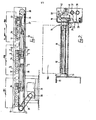
- the conveyor shown in Figures 1 to 11 is for transporting goods units,indicated in Figure 1 as a series of boxes 10,three of which are identified as 10A, 10B, 10C.
- the direction of travel is indicated by arrow 11.
- the goods rest on a plurality of parallel rollers 12 arranged transversely of the length of the conveyor and disposed in groups of four. These are positioned at respective stations identified at A, B and C respectively and there may be any number of groups arranged in line and curves can be incorporated, as will be described.
- rollers 12 are cylindrical and are mounted on bearings 13, 14 carried in brackets 15, 16 secured to fixed channel-shaped side members 17, 18,of which the flanges are presented outwardly.
- each roller 12 Through the centre of each roller 12 is a shaft 19 carrying end plugs frictionally engaged within a sleeve forming the roller.
- a drive and clutch mechanism This is shown particularly at the right hand side of Figure 2 and in Figure 3.
- a clutch member 22 is axially slideable but non-rotatably fixed.
- a sprocket 21 is rotatably mounted on the said shaft 19.
- the sprocket 21 and the clutch member 22 have respective inter-engageable dogs at 23, 24.
- the sprocket 21 and/or clutch member 22 are made from a low friction material such as nylon.
- the sprocket 21 engages a chain 26 extending lengthwise of the conveyor and running over end sprockets 27, 28. Suitable guides and supports are mounted to regulate the chain runs.
- the upper run of the chain 26 engages with the sprockets 21 at each roller position.
- the chain sprocket 27 is on a shaft carrying a sprocket engaging a chain 29 arranged to be driven from a further sprocket 30 driven, in use, by an electric motor 31 below the conveyor.
- Each shaft of these other rollers carries a gear 33 and, in the case of the roller with which the clutch member 22 is associated, there is a gear 32 formed integrally as part of the clutch member 22.
- the gears 33 are non-rotatably fixed onto their respective shafts. Meshing with the gears 32 and 33 are intermediate gears 34.
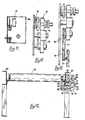
- Figure 4 shows a mounting for one of these intermediate gears 34 comprising a headed bolt 35 engaged in the side member 18.
- a spacer sleeve 36 holds the gear 34 in its correct position.
- the gear 34 is somewhat deeper than the two gears with which it meshes as shown in Figure 3.
- a clutch mechanism includes a clutch actuating tube 37 which is rotatably mounted in bearings 38, 39 and extending lengthwise of the conveyor. Secured to the tube 37 is a pair of fingers 41 with inwardly directed pins which engage in a groove 42 in the clutch member 22. This arrangement is seen particularly in Figure 2.
- a sensor roller 43 of full track width Adjacent each group of four rollers, and in front of the group, there is a sensor roller 43 of full track width. This is therefore positioned at the side of the associated group in the direction of transport so that, as seen in Figure 1, the goods 10 will travel across the driven rollers and then reach-the sensor roller 43.
- One end of the sensor roller 43 is mounted on one limb of a bell crank lever 44 pivoted at its midpoint on the fixed side member 18 of the conveyor.
- the other end of the sensor roller is carried on a similar lever (not shown) connected to the bell crank lever by a rigid arm 45 and by a counterbalance bar 50 so that this assembly can swing together.
- the bell crank lever 44 carries a pin 46 engaging in a shaped clutch actuating arm 47.
- the connection between the pin 46 and the shaped arm 47 allows some relative angular movement as well as pivotal movement between them.
- the shaped arm is formed as a pressing with two flanges pivotally connected to a lug 48 on the tube 37 through a pivot pin 49.
- the arm is shaped partially to embrace the tube 37 through less than 180°.
- the sensor roller 43 In response to arrival of a goods unit into one of the stations, the sensor roller 43 is depressed. This causes the bell crank lever 44 to swing so that the pin 46 moves the shaped arm 47. If the shaped arm is constrained to remain in contact with the tube 37, the movement of the shaped arm 47 will be accompanied by angular movement of the tube 37. Such angular movement swings the associated fingers 41 to bring the clutch member 22 out of engagement with the sprocket 21. The sprocket will, however, continue to rotate since it is continuously driven by the chain 26 but it will simply rotate on the shaft 19 without transmitting any rotation to it. As the clutch is disengaged, the other three shafts 19 in the same group of rollers will also cease to rotate.
- the mechanism comprises a forked or double preparation lever 51 which is generally of inverted L-shape.
- the shorter upper portion carries a pair of rollers 52 on a short pivotted member 53.
- a steadying arm 54 connects this upper end of the preparation lever 51 with the side member 18 of the conveyor.
- the lower end of the preparation lever 51 has a curved portion in which is an oval hole 55 in which engages a pin 56 on a lug 57 carried on a preparation tube 58 mounted below the tube 37 on a further bracket in the side member 18.
- the lower end of the lever 51 is curved generally below the preparation tube 58.
- the lug 57 swings downwardly, when the tube 58 moves in an anti-clockwide direction, as indicated in Figure 4, to bring the lower end of the lever 51 to the bottom dead centre position, thus resisting any tendency for reverse forces to lift the rollers 52 off the lever 47.
- bell crank lever 59 also pivoted on the side member of the conveyor, one end being slotted to engage over the pin 46, at its opposite end from the shaped arm 47.
- the other end of the bell crank lever 59 carries a pin 61. This engages in a slot in one end of a lever 62 which is tangentially secured to the preparation tube 58.
- the bell crank levers 44 and 59 swing in opposite directions when the sensor roller 43 is depressed.
- the shaped arm 47 and the lever 62 pass through respective openings in the side member 18.
- the arrangement is such that when the sensor roller is depressed the bell crank lever 44 causes the shaped lever to be moved down, through the pin 46 but the lever 61 is moved up simultaneously.
- the rollers 52 are brought down into contact with the shaped lever 47 to produce rotation of the tube 37 to disengage the clutch.
- a finger 37a and a corresponding finger 58a is provided on the preparation tube 58. As shown in Figure 4, these are in contact with one another. This corresponds with the clutch engaged position.
- the preparation lever 51 is moved downwardly by angular movement of the preparation tube 58 in an anti-clockwise direction.
- the shaped lever 47 is moved, this will cause the tube 37 to be moved angularly in a clockwise direction, thus disengaging the clutch.
- the clutch actuating tube 37 will be pushed in an anti-clockwise direction, to re-engage the clutch. It will, however, be understood that it is the sensor roller 43 of the station in front, or downstream of the conveyor which controls the relevant clutch in the manner described.
- the arrangement in use is that the goods units 10 will move along the conveyor while all the drivable rollers 12 remain in driving condition, with the clutches in each group engaged. As one of the units 10A reaches the delivery end of the conveyor, it will depress the sensor roller 43 at the end station.
- a signal may be produced which alerts an operator to the need to control the conveyor or, alternatively, the unit 10A may be allowed to continue off the end of the conveyor to another machine or other destination as required.
- Control of the conveyor may involve allowing goods units to accumulate and be stored on the conveyor. However, the goods may arrive irregularly and thus it is required that they should fill the stations in turn and, at least in this example, be spaced apart at equal spacing as shown.
- the signal triggered by the arrival of a goods unit 10A at the end or last station, may generate an automatic response to the equipment downstream of the conveyor.
- an actuator controls angular movement of the preparation tube 58 in station A. As this occurs, the unit 10A will stop.
- the bell crank levers 44 and 59 will move. Movement of the bell crank lever 59 transmits movement to the preparation lever 51 to bring the rollers 52 carried thereby into contact with the shaped arm 47. This brings the station B into readiness to stop the group of rollers 12 at that station. However, this will not occur until the next unit 10B arrives in station B and depresses the sensor roller 43 in that station. The movement of that sensor roller 43 now moves the tube 37 which disengages the clutch for the group of four rollers in this station. This is then arranged to produce movement of the bell preparation tube 58 for the next group of rollers 12 at station C to bring these into readiness to be disengaged when a further unit arrives in that station. The sequence, as described, will recur until all stations are filled.
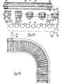
- Figures 8, 9, 10 show a bend which can be incorporated in a conveyor run. Although a 90° bend is shown, any angle can be used, as may be required.
- the rollers 63 are arranged at respective angles, as shown.
- the clutches and associated mechanisms are situated on the outside of the end and are mounted on the side member 64.
- the rollers 63 are arranged in groups of eight with a sensor roller 65 at the front.
- the type of mechanism is the same as that shown in the apparatus in Figures 1 to 7.
- the tubes equivalent to the tubes 58 have to be jointed.
- the operative parts of these tubes are identified at 66 and extensions 67 are connected through universal joints 68. These are, furthermore, supported by brackets 69.
- the drive chain 71 also requires some guidance in order to carry it around the bend without risk that it will leave the sprockets.
- the bend apparatus may be a separate unit, for incorporation in a complete conveyor system or it may be built in, using the same drive chain as adjacent straight sections.
- Figure 9 shows two adjacent rollers 63 and the gears 72, 73 carried on their shafts, the gear 72 being associated with the clutch mechanism 74.
- the gears 72, 73 are both in mesh with an intermediate gear 75. The depth of this is greater than the gears 72, 73.
- Figure 11 also shows a guard 18A which encloses the entire mechanisms.
- the guard is of simple channel shape and is easily removed or replaced without complex dismantling of other parts. This type of guard may be used on the bend as well as on the straight sections.
- gears 32, 33, 34 are mounted in a different manner, allowing some adjustment and also shown is a means 76 which is designed to restrain the sprocket 21 against outward movement when the clutch is disengaged.
- Figure 13 shows a further alternative arrangement in which adjacent rollers 1, 2, not including that having the clutch mechanism, are interconnected by short chains 77 engaged on sprockets 78, 79. On conveyors which are designed for lighter loads, belts may be substituted.
- the conveyor shown in Figures 14, 15, 16 includes rollers 81.
- rollers 81 are similar to those in the construction shown in Figures 1 to 11 and are mounted in channel shaped side members 82, 83.
- this form of conveyor has individual clutches for each roller 81. It can be seen from Figure 14 that there are tubes 84, equivalent to the tubes 37 which are, however, longer, extending below all the rollers 81 in each group. These tubes carry spaced pairs of forks 85 engaging clutch mechanisms on each roller spindle, the clutch mechanisms being of the same design as those already described.
- each group of rollers 81 In front of each group of rollers 81 is a sensor roller 86 carried on bell crank levers, one of which is shown at 87 in Figure 16. This is, in turn, connected to a second bell crank lever 88. A connecting pin 89 engages -in a slot to allow for the required relative movement between the bell crank levers 87, 88. A shaped arm clutch actuator 9l,engaged on the end of the pin 89, through a slot in that arm, partially surrounds the tube 84 and is pivotted to a lug 92 on the tube 84 by a pin 93. To hold the shaped arm 91 into contact with the tube 84 there is a roller 94 carried by an inverted L-shaped preparation lever 95 which, at its lower end, is connected to a lug 96 on a lower, preparation tube 97.
- FIG. 24 shows an alternative arrangement which is intended to ensure that the clutches will actuate simultaneously, particularly when closing or engaging.
- Each of the clutch members 98 carried on the spindles 99 are grooved to carry thin belts 101 connecting adjacent clutch members 98. Any rotation of one clutch member 98, when the clutches are disengaged, will therefore be accompanied by rotation of all the others in the group, so that when they are to be re-engaged, all the dogs will be in correct positions for re-engagement.
- Figures 17 and 18 show an alternative arrangement in which the tube 102, equivalent to tube 37, has a lobe 103 and is pivotally carried on an arm 104 secured to the conveyor side member 109.
- a pivotted lever 105 Over the tube and lobe is a pivotted lever 105 which can be held down by a roller 106 or not as the case may be.
- This lever 105 is pivotally connected to a lug on the tube 102.
- the roller 106 is carried on a double arm 107 pivotted to a bracket 108 secured to the side member 109.
- a lever 110 connects the arm 107 and the lobe 103 to a lug 111 on the lower, preparation tube 112.
- the roller 106 may, in another example, be replaced by a shoe.
- Figures 19 and 20 show a further alternative arrangement in which a shaped arm 113 is similar to the shaped arm 37, as seen in Figure 4. Bearing on this is a roller 114 carried on a double arm 115 pivotted to a bracket 116 on the side member 117. A lever 118 is connected to the lower, preparation tube 119 through a lug 121, as in Figure 17. In this example, the shaped arm 113 is below the side member 117.
- Figure 21 shows, in cross-section, a form of the roller which enables drive to the actual bad carrying surface of the roller to be discontinued, other than by the clutch arrangements, if some obstruction stops or slows the goods which are resting, for the time being, on a roller or group of rollers. This prevents excessive pressure building up between adjacent units if they become closed up together.
- the roller comprises a cylindrical tube 122 through the interior of which the shaft 123 passes.
- Plugs 124, 125 in each end of the tube 122 are fixed to the shaft 123 in non-rotatable manner.
- Each of the plugs in this example, is a generally cylindrical part having a flange at one end and a nylon or other low friction sleeve 126.
- the whole plug 127 is made from nylon or other low friction material.
- the roller end opposite to the sprocket and clutch member has a plug incorporating a ball bearing 128.
- the chain and sprockets may be replaced by a lay shaft running the length of the conveyor and sets of meshing bevel gears, one of each set replacing the sprocket and the other being secured on the lay shaft.
- Figure 25 shows an alternative arrangement of a drive chain 129 for driving all the sprockets 131 on the respective rollers.
- a further sprocket 132 is placed between the ends of adjacent roller groups and the chain 129 is passed under this so as to give engagement over a greater portion of the periphery of the sprocket 132, as well as over the adjacent roller sprockets 131.
- This Figure also shows an alternative drive and tensioning arrangement for the chain, incorporating a drive sprocket I33 and a tensioning sprocket 134.
- Figure 26 shows an alternative bend construction, made up as a separate unit. This has a curved section and two straight sections. Two alternative drive motor mountings are shown. In one example the motor 135 is mounted below the conveyor and in the other example, where access below is limited, the motor may be mounted at 136, laterally of the conveyor.
- Control of the conveyor will involve allowing goods units to accumulate and be stored on the conveyor. However, the goods may arrive irregularly and thus it is required that they should fill the stations in turn and, at least in this example, be spaced apart at equal spacing as shown.
- the signal triggered by the arrival of a goods unit 10 at the end or last station A may be for manual selection or may produce an automatic response generated by following equipment or otherwise.
- the actuator controls angular movement of the tube 37 in station A.
- Such actuator (which is not shown in the drawings) may be a motorised actuator, air cylinder or electrical or mechanical device which moves the tube angularly, as described, when required.
- rollers on vertical axes to the tops of the two side members, to serve as guides to control the goods units as they move along the conveyor. This reduces frictional contact between the goods and the conveyor, along the sides.
Landscapes
- Engineering & Computer Science (AREA)
- Mechanical Engineering (AREA)
- Rollers For Roller Conveyors For Transfer (AREA)
- Structure Of Belt Conveyors (AREA)
- Threshing Machine Elements (AREA)
Priority Applications (1)
| Application Number | Priority Date | Filing Date | Title |
|---|---|---|---|
| AT86300867T ATE43554T1 (de) | 1985-02-16 | 1986-02-10 | Foerderer. |
Applications Claiming Priority (4)
| Application Number | Priority Date | Filing Date | Title |
|---|---|---|---|
| GB858504031A GB8504031D0 (en) | 1985-02-16 | 1985-02-16 | Conveyors |
| GB8504031 | 1985-02-16 | ||
| GB858516141A GB8516141D0 (en) | 1985-06-26 | 1985-06-26 | Conveyors |
| GB8516141 | 1985-06-26 |
Publications (3)
| Publication Number | Publication Date |
|---|---|
| EP0192389A2 true EP0192389A2 (de) | 1986-08-27 |
| EP0192389A3 EP0192389A3 (en) | 1987-04-29 |
| EP0192389B1 EP0192389B1 (de) | 1989-05-31 |
Family
ID=26288825
Family Applications (1)
| Application Number | Title | Priority Date | Filing Date |
|---|---|---|---|
| EP86300867A Expired EP0192389B1 (de) | 1985-02-16 | 1986-02-10 | Förderer |
Country Status (5)
| Country | Link |
|---|---|
| US (1) | US4752000A (de) |
| EP (1) | EP0192389B1 (de) |
| AT (1) | ATE43554T1 (de) |
| DE (1) | DE3663649D1 (de) |
| ES (1) | ES8705325A1 (de) |
Cited By (1)
| Publication number | Priority date | Publication date | Assignee | Title |
|---|---|---|---|---|
| EP4699960A1 (de) * | 2024-08-22 | 2026-02-25 | König Maschinenbau GmbH | Rollenbahn zum fördern von fördergut sowie verfahren zum betrieb der rollenbahn |
Families Citing this family (6)
| Publication number | Priority date | Publication date | Assignee | Title |
|---|---|---|---|---|
| DK161591C (da) * | 1989-03-01 | 1991-12-30 | Univeyor As | Akkumuleringstransportoer |
| DE19841608A1 (de) * | 1998-09-11 | 2000-03-23 | Axmann Foerdertechnik | Rollenförderbahn |
| JP2004083249A (ja) * | 2002-08-28 | 2004-03-18 | Nippon Yusoki Co Ltd | 移載装置 |
| US20070034488A1 (en) * | 2005-08-09 | 2007-02-15 | Tuan-Mei Chiu Chen | Roller-type conveying machine |
| US20080135356A1 (en) * | 2006-12-06 | 2008-06-12 | Yungh-Siang Lin | Transmission motor structure |
| US8763789B2 (en) | 2012-03-08 | 2014-07-01 | Tgw Systems, Inc. | Drive system for curved roller conveyor segments |
Family Cites Families (26)
| Publication number | Priority date | Publication date | Assignee | Title |
|---|---|---|---|---|
| US597114A (en) * | 1898-01-11 | Sheet-delivery mechanism for printing-presses | ||
| US2883172A (en) * | 1955-08-04 | 1959-04-21 | Reynolds Metals Co | Apparatus for the heat treatment of metallic sheet material |
| US3327837A (en) * | 1966-06-17 | 1967-06-27 | Uniroyal Inc | Clutch drive for conveyor roll |
| US3513960A (en) * | 1968-01-17 | 1970-05-26 | Gifford Wood Inc | Accumulator conveyor |
| DE1556724C3 (de) * | 1968-03-02 | 1974-10-03 | Demag Ag, 4100 Duisburg | Rollenförderbahn |
| US3610406A (en) * | 1968-03-20 | 1971-10-05 | Gen Logistics | Conveyor constructions and torque-limiting transmissions therefor |
| DE1756329A1 (de) * | 1968-05-08 | 1970-04-30 | Stein Ohg Hans | Stueckgutrollenbahn |
| US3537568A (en) * | 1969-01-10 | 1970-11-03 | John M Leach | Article handling conveyors |
| NL7107537A (de) * | 1970-06-16 | 1971-12-20 | ||
| US3716129A (en) * | 1971-04-22 | 1973-02-13 | A Sadler | Accumulating live roller conveyor |
| DE2211982C3 (de) * | 1972-03-13 | 1979-06-07 | Richard 6920 Sinsheim Gebhardt | Staurollenbahn mit Antrieb über ZwischenroUen |
| US3840110A (en) * | 1972-07-24 | 1974-10-08 | Ermanco Inc | Conveyor apparatus |
| DE2517015C2 (de) * | 1975-04-17 | 1983-03-31 | Richard 6920 Sinsheim Gebhardt | Rollenbahn zum Fördern und Stauen von Stückgut |
| DE2519374C2 (de) * | 1975-04-30 | 1986-01-09 | Interroll-Fördertechnik GmbH & Co KG, 5632 Wermelskirchen | Abschaltbare Treibrolle für Rollenförderbahnen |
| CH607975A5 (en) * | 1976-02-23 | 1978-12-15 | Stoecklin Walter Ag | Line of accumulating rollers |
| DE2650205C2 (de) * | 1976-11-02 | 1984-08-02 | Richard 6920 Sinsheim Gebhardt | Staurollenbahn zum Fördern und drucklosen Stauen von Stückgut |
| US4164998A (en) * | 1977-02-16 | 1979-08-21 | David A. DeGood | Accumulation live roller conveyor |
| US4193492A (en) * | 1977-09-15 | 1980-03-18 | Hammond Theodore A | Line shaft drive for powered roller conveyor |
| AU4522079A (en) * | 1978-03-21 | 1979-09-27 | Conveyor Manufacturing Company Limited | Roller conveyors |
| US4325474A (en) * | 1978-06-05 | 1982-04-20 | Rexnord Inc. | Slip friction roller drive |
| DE2853483C2 (de) * | 1978-12-12 | 1985-08-29 | geb. Kramer Elfriede 6920 Sinsheim Gebhardt | Stauförderer für Stückgut |
| GB2098566A (en) * | 1981-05-14 | 1982-11-24 | Dunn W H & Son Ltd | Driving roller conveyors |
| AT381080B (de) * | 1981-06-10 | 1986-08-25 | Amon Gerhard Ing | Staurollenbahn |
| US4488638A (en) * | 1982-05-27 | 1984-12-18 | Figgie International Inc. | Live roller accumulating brake conveyor |
| AU3895785A (en) * | 1984-02-27 | 1985-09-05 | Sally L. Adkins | Chest band |
| GB8406923D0 (en) * | 1984-03-16 | 1984-04-18 | Dexion Comino Int Ltd | Accumulation conveyors |
-
1986
- 1986-02-10 DE DE8686300867T patent/DE3663649D1/de not_active Expired
- 1986-02-10 EP EP86300867A patent/EP0192389B1/de not_active Expired
- 1986-02-10 AT AT86300867T patent/ATE43554T1/de not_active IP Right Cessation
- 1986-02-13 US US06/829,069 patent/US4752000A/en not_active Expired - Fee Related
- 1986-02-14 ES ES552057A patent/ES8705325A1/es not_active Expired
Cited By (1)
| Publication number | Priority date | Publication date | Assignee | Title |
|---|---|---|---|---|
| EP4699960A1 (de) * | 2024-08-22 | 2026-02-25 | König Maschinenbau GmbH | Rollenbahn zum fördern von fördergut sowie verfahren zum betrieb der rollenbahn |
Also Published As
| Publication number | Publication date |
|---|---|
| US4752000A (en) | 1988-06-21 |
| ATE43554T1 (de) | 1989-06-15 |
| ES8705325A1 (es) | 1987-05-01 |
| ES552057A0 (es) | 1987-05-01 |
| DE3663649D1 (en) | 1989-07-06 |
| EP0192389A3 (en) | 1987-04-29 |
| EP0192389B1 (de) | 1989-05-31 |
Similar Documents
| Publication | Publication Date | Title |
|---|---|---|
| US4883163A (en) | Apparatus and method for regularly spacing apart randomly spaced objects while conveying them | |
| US4362238A (en) | Selective drive arrangement for roller conveyor | |
| EP4041662B1 (de) | Sammler mit umlenkvorrichtung zum sammeln von gegenständen | |
| EP0453407B1 (de) | Verfahren und Vorrichtung zur Bildung von Gruppen von Nahrungsmittelscheiben | |
| EP1849725B1 (de) | Förderer zum Transport und Aufstauen von einzelnen Produkten | |
| GB2073691A (en) | Drive means for srting and/or conveying system | |
| EP0192389A2 (de) | Förderer | |
| EP0077304A2 (de) | Sortier-, Verteil- und Stapelmaschine für keramische Produkte und Fliesen | |
| US4147011A (en) | Bottle treating apparatus | |
| ITBO930522A1 (it) | Dispositivo per l'estrazione in continuo di articoli da una linea principale a uscite intermedie poste angolarmente rispetto a tale linea | |
| EP0127459A2 (de) | Verpackungsmaschine | |
| CA1105903A (en) | Nestable container packaging apparatus | |
| SE466749B (sv) | Arkmatningsanordning | |
| EP2668124B1 (de) | Ringförderer | |
| CN107187795B (zh) | 可自动变换节距的物料传输装置 | |
| JPH0262445B2 (de) | ||
| EP1003675B1 (de) | Transfermechanismus | |
| EP0447123B1 (de) | Zufuhr- und Gruppierungsmechanismus für eine Verpackungsmaschine | |
| US5377817A (en) | Bi-directional accumulation roller conveyor | |
| US3561584A (en) | Apparatus for feeding pulpwood to a conveyor of a device for charging defiber magazines | |
| US4247238A (en) | Stacking and unstacking apparatus | |
| US2320934A (en) | Accumulator | |
| US3105584A (en) | Overhead material handling conveyor | |
| US4052837A (en) | Multiple pouch bagging apparatus | |
| SU908709A1 (ru) | Питатель |
Legal Events
| Date | Code | Title | Description |
|---|---|---|---|
| PUAI | Public reference made under article 153(3) epc to a published international application that has entered the european phase |
Free format text: ORIGINAL CODE: 0009012 |
|
| AK | Designated contracting states |
Kind code of ref document: A2 Designated state(s): AT BE CH DE FR GB IT LI LU NL SE |
|
| PUAL | Search report despatched |
Free format text: ORIGINAL CODE: 0009013 |
|
| AK | Designated contracting states |
Kind code of ref document: A3 Designated state(s): AT BE CH DE FR GB IT LI LU NL SE |
|
| 17P | Request for examination filed |
Effective date: 19870909 |
|
| 17Q | First examination report despatched |
Effective date: 19871111 |
|
| GRAA | (expected) grant |
Free format text: ORIGINAL CODE: 0009210 |
|
| AK | Designated contracting states |
Kind code of ref document: B1 Designated state(s): AT BE CH DE FR GB IT LI LU NL SE |
|
| PG25 | Lapsed in a contracting state [announced via postgrant information from national office to epo] |
Ref country code: IT Free format text: LAPSE BECAUSE OF FAILURE TO SUBMIT A TRANSLATION OF THE DESCRIPTION OR TO PAY THE FEE WITHIN THE PRE;WARNING: LAPSES OF ITALIAN PATENTS WITH EFFECTIVE DATE BEFORE 2007 MAY HAVE OCCURRED AT ANY TIME BEFORE 2007. THE CORRECT EFFECTIVE DATE MAY BE DIFFERENT FROM THE ONE RECORDED.SCRIBED TIME-LIMIT Effective date: 19890531 Ref country code: AT Effective date: 19890531 Ref country code: NL Effective date: 19890531 Ref country code: BE Effective date: 19890531 |
|
| REF | Corresponds to: |
Ref document number: 43554 Country of ref document: AT Date of ref document: 19890615 Kind code of ref document: T |
|
| REF | Corresponds to: |
Ref document number: 3663649 Country of ref document: DE Date of ref document: 19890706 |
|
| ET | Fr: translation filed | ||
| NLV1 | Nl: lapsed or annulled due to failure to fulfill the requirements of art. 29p and 29m of the patents act | ||
| PGFP | Annual fee paid to national office [announced via postgrant information from national office to epo] |
Ref country code: GB Payment date: 19900131 Year of fee payment: 5 |
|
| PGFP | Annual fee paid to national office [announced via postgrant information from national office to epo] |
Ref country code: FR Payment date: 19900210 Year of fee payment: 5 |
|
| PGFP | Annual fee paid to national office [announced via postgrant information from national office to epo] |
Ref country code: SE Payment date: 19900223 Year of fee payment: 5 |
|
| PG25 | Lapsed in a contracting state [announced via postgrant information from national office to epo] |
Ref country code: LU Free format text: LAPSE BECAUSE OF NON-PAYMENT OF DUE FEES Effective date: 19900228 Ref country code: LI Effective date: 19900228 Ref country code: CH Effective date: 19900228 |
|
| PGFP | Annual fee paid to national office [announced via postgrant information from national office to epo] |
Ref country code: DE Payment date: 19900228 Year of fee payment: 5 |
|
| PLBE | No opposition filed within time limit |
Free format text: ORIGINAL CODE: 0009261 |
|
| STAA | Information on the status of an ep patent application or granted ep patent |
Free format text: STATUS: NO OPPOSITION FILED WITHIN TIME LIMIT |
|
| 26N | No opposition filed | ||
| REG | Reference to a national code |
Ref country code: CH Ref legal event code: PL |
|
| PG25 | Lapsed in a contracting state [announced via postgrant information from national office to epo] |
Ref country code: GB Effective date: 19910210 |
|
| PG25 | Lapsed in a contracting state [announced via postgrant information from national office to epo] |
Ref country code: SE Effective date: 19910211 |
|
| GBPC | Gb: european patent ceased through non-payment of renewal fee | ||
| PG25 | Lapsed in a contracting state [announced via postgrant information from national office to epo] |
Ref country code: FR Effective date: 19911031 |
|
| PG25 | Lapsed in a contracting state [announced via postgrant information from national office to epo] |
Ref country code: DE Effective date: 19911101 |
|
| REG | Reference to a national code |
Ref country code: FR Ref legal event code: ST |
|
| EUG | Se: european patent has lapsed |
Ref document number: 86300867.8 Effective date: 19911008 |