EP0192455A2 - Condenseur de laboratoire en matière plastique - Google Patents
Condenseur de laboratoire en matière plastique Download PDFInfo
- Publication number
- EP0192455A2 EP0192455A2 EP86301105A EP86301105A EP0192455A2 EP 0192455 A2 EP0192455 A2 EP 0192455A2 EP 86301105 A EP86301105 A EP 86301105A EP 86301105 A EP86301105 A EP 86301105A EP 0192455 A2 EP0192455 A2 EP 0192455A2
- Authority
- EP
- European Patent Office
- Prior art keywords
- heat transfer
- condenser according
- shell
- condenser
- disc
- Prior art date
- Legal status (The legal status is an assumption and is not a legal conclusion. Google has not performed a legal analysis and makes no representation as to the accuracy of the status listed.)
- Granted
Links
Images


Classifications
-
- B—PERFORMING OPERATIONS; TRANSPORTING
- B01—PHYSICAL OR CHEMICAL PROCESSES OR APPARATUS IN GENERAL
- B01L—CHEMICAL OR PHYSICAL LABORATORY APPARATUS FOR GENERAL USE
- B01L7/00—Heating or cooling apparatus; Heat insulating devices
-
- F—MECHANICAL ENGINEERING; LIGHTING; HEATING; WEAPONS; BLASTING
- F28—HEAT EXCHANGE IN GENERAL
- F28B—STEAM OR VAPOUR CONDENSERS
- F28B1/00—Condensers in which the steam or vapour is separate from the cooling medium by walls, e.g. surface condenser
- F28B1/02—Condensers in which the steam or vapour is separate from the cooling medium by walls, e.g. surface condenser using water or other liquid as the cooling medium
-
- Y—GENERAL TAGGING OF NEW TECHNOLOGICAL DEVELOPMENTS; GENERAL TAGGING OF CROSS-SECTIONAL TECHNOLOGIES SPANNING OVER SEVERAL SECTIONS OF THE IPC; TECHNICAL SUBJECTS COVERED BY FORMER USPC CROSS-REFERENCE ART COLLECTIONS [XRACs] AND DIGESTS
- Y10—TECHNICAL SUBJECTS COVERED BY FORMER USPC
- Y10S—TECHNICAL SUBJECTS COVERED BY FORMER USPC CROSS-REFERENCE ART COLLECTIONS [XRACs] AND DIGESTS
- Y10S165/00—Heat exchange
- Y10S165/905—Materials of manufacture
Definitions
- This invention relates to compact plastics material condensers, which are useful generally in laboratory, industrial, service or domestic applications where glass condensers would usually be used.
- Glass condensers are used in virtually all chemical laboratories, because of their excellent chemical resistance to most corrosives and because of their transparency.
- glass is a highly brittle material subject to catastrophic failure by relatively low impacts and thermal shock, particularly in thick sections. Glass is also very sensitive to scratches, nicks and other defects which act as stress raisers, resulting in failure at the slightest impact.
- a variety of plastics materials, particularly the fluoroplastics are also highly resistant to most corrosives, even more so than borosilicate glass. Many are transparent or translucent, resistant to breakage and relatively economical to produce. However, plastics materials have low thermal conductivity, about 1/4 to 1/6 that of glass, and are therefore poorly suited for making condensers.
- Some industrial type heat exchangers, of the shell and tube type utilize a large number of small bore tetrafluoroethylene (TFE) fluoroplastic tubes having a large surface area for heat transfer. Such exchangers are generally not suitable for laboratory use.
- TFE tetrafluoroethylene
- This invention provides an impact-resistant compact condenser, having excellent chemical resistance and good heat transfer performance and which is much safer to use than glass, comprising a plastics shell enclosing at least one heat transfer disc dividing it into at least one cooling cell and at least one vapour cell, means for retaining the disc in sealed abutment against the plastics shell and each of the cells having inlet and outlet ports.
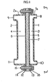
- the condenser comprises plastics side walls 1,2 having respective cylindrical peripheral walls (1a,2a).
- a heat transfer disc 7 is disposed between the peripheral walls (1a,2a) of the side walls 1, 2 so as to divide the condenser into a vapour cell 4 and a cooling cell 3.
- the shell wall 2 of vapour cell 4 is provided with a vapour inlet port 9 and a condensate outlet port 11.
- the shell wall 1 of the cooling cell 3 is provided with a cooling inlet port 10 and an outlet port 8.
- the peripheral parts (1a,2a) of the shell walls 1,2 are provided with an annular flange 13, 12, respectively.
- the disc 7 is disposed between the flanges 12 and 13 and is secured in position by fastening means 15.
- reinforcing rings 14 and 16 are disposed between the fastening means 15 and the flanges 12 and 13 respectively for improved durability.
- FIG. 2 another embodiment of the present invention is shown, wherein the condenser is provided with plastics shell side walls 21 and 22. Disposed between the side walls 21 and 22 is a heat transfer disc 27, which divides the condenser into a cooling cell 23 and a vapour cell 24.
- the side wall 21 is provided with a liquid coolant inlet port 30 and an outlet port 28.
- the side wall 22 is provided with a vapour inlet port 29 and a condensate outlet port 31.
- the heat transfer disc 27 is provided with a plastics film coating 25 on its cooling cell side and a plastics film coating 26 on the vapour cell side.
- the side walls 21, 22 and the heat transfer disc 27 are held together by a compression shrink ring 32 disposed around the periphery of the side walls 21, 22.
- the side walls 21 and 22 have a substantially convex contour with respect to the heat transfer disc 27.
- FIG. 3 another embodiment of the present invention is shown, wherein two heat transfer discs 46 and 47 are provided.
- the condenser is provided with exterior shell side walls 41, 42.
- a plastics circumferential ring 60 is disposed between the side walls 41 and 42.
- the ring 60 and the side walls 41, -42 are held together by compression shrink rings 52, 53.
- any desired means may be used for maintaining together the side walls 41, 42 and the circumferential ring 60.
- the heat transfer discs 46, 47 are disposed within the condenser so as to divide it into cooling cells 43, 45 and a vapour cell 44, located between the cooling cells 43, 45.
- the heat transfer discs 46, 47 are disposed in any convenient position so long as they are sufficiently spaced apart to provide room for the entry and discharge of the cooling liquid, vapour and condensate.
- the heat transfer discs 46, 47 are positioned where the circumferential ring 60 meets the side walls 42 and 41.
- the vapour cell 44 is provided with an inlet port 49 and an outlet port 51, which are incorporated in the ring 60.
- the cooling cell 43 is provided with an inlet port 50 and an outlet port 48 in the side wall 41 and the cooling cell 45 is provided with an inlet port 55 and an outlet port 54 in the side wall 42.
- the heat transfer disc 46 is provided with plastics films 56 and 57 on its respective cooling and vapour cell sides.
- the heat transfer disc 47 is also provided with plastics films 58 and 59 on its cooling and vapour cell sides respectively.
- the condenser is provided with plastics shell side walls 61, 62 which are substantially identical to the shell walls 1 and 2 of Figure 1.
- a heat transfer disc 67 is provided, which divides the condenser into a cooling cell 63 and a vapour cell 64.
- the side wall is provided with a liquid coolant inlet port 70 and an outlet port 68 and the side wall 62 is provided with a vapour inlet port 69 and a condensate exit port 71.
- This condenser is very similar to that of Figure 1, except that the means for holding the shell walls together are different and the heat transfer disc 67 does not have a protective film as shown at 5,6 in Figure 1.
- the outer peripheral parts of the side walls 61 and 62 are provided with a flange 73, 72, respectively, and a heat transfer disc 77 is disposed therebetween.
- the flanges 72, 73 of the side walls 61 and 62 are clamped together by means of separable clamping rings 74, 76, held together by nut and bolt fastening means 75.
- the two plastics shell sides are moulded, generally with inlet and outlet ports or openings.
- the centre circumferential plastics ring with inlet and outlet ports or openings is also moulded.
- Injection moulding is the preferred manufacturing method, but other moulding techniques well known to those in the field, such as compression moulding, can also be used.
- the condenser of the present invention is unique in that it combines a number of favourable characteristics and properties not found in any laboratory condenser, to the best of our knowledge. Thus it is compact, yet has a heat transfer performance as good as and, in many embodiments, superior to that of conventional glass laboratory condensers. It is impact-resistant and therefore much safer to use than all-glass condensers.
- the shell may be translucent or it may be transparent, in order to allow viewing of the water cooling cell and the vapour cell, higher visibility being desired in the vapour cell.
- a glass heat transfer disc can be safely used, since it is anti-shock-mounted inside the plastics shell and is thus fail-safe.
- the separable shell embodiments, heat exchange discs and shell side walls can be changed to different types.
- the geometry of the condenser is essentially disc-shaped, as are the cells and the heat transfer wall (the heat transfer disc).
- the side walls of the disc are preferably substantially flat and substantially parallel to one another.
- the disc is also preferably positioned so that the sides are aligned substantially parallel to the shell walls, as shown in Figure 1.
- the disc may have some other cross-sectional shape, for example, it may have a corrugated cross-section.
- the side walls of the disc are preferably smooth, so as to minimize the collection of impurities on the surface and thereby reduce the efficiency of the device.
- the disc-shaped cells give a relatively high volume for a high water flow and very little pressure drop, to give an effective cooling, and the disc-shaped vapour cell holds a relatively large volume of vapour.
- a disc condenser having a diameter of 15 cm (6 inches) has a cooling water cell volume of 375 cc, compared to a spiral Friedrich-type glass condenser ( 32 cm (121 ⁇ 2 inches) in length x 5 cm (2 in) O.D.), which has a cooling water volume of 140 cc, namely about 1/3 of that of the disc type of condenser.
- the vapour volume of a Friedrich glass condenser is 145 cc, compared to 325 cc for the disc condenser of the invention, viz. less than 1/2 that of the disc condenser.
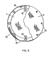
- the geometry of the condenser or disc shown as circular in Figures 1 and 5, can also be hexagonal, octagonal, square, rectangular, etc., with relatively narrow parallel cells; however, the disc shape lends itself to ease of fabrication and production and has good economy and is therefore the preferred shape.
- the term "disc” is to be taken to cover any of the foregoing configurations including circular.
- the side wall of the disc on the vapour cell side is preferably spaced such a distance from the shell as to cause turbulent flow in the vapour cell.
- the side wall of the disc on the cooling cell side may be spaced from the shell a distance sufficient for proper heat transfer.
- the heat transfer disc may be a composite of a graphitic material with plastics coating, e.g. of the polymers previously mentioned and given in the following examples.
- Metallic substrates are also suitable as composites with plastics coatings or with one coating on the vapour side of the disc or, in some embodiments, with uncoated surfaces.
- Borosilicate glass or glass-ceramic discs without coatings are also useful embodiments, as are glassed steel or glass-ceramic-coated steel.
- the glass disc is coated with a thin film of a fluoroplastics material on the vapour side of the disc.
- the protective film coating of a chemically-resistant material on the disc should be thin for minimal resistance to heat transfer, but of sufficient substance to be resistant to vapour or liquid penetration into the graphitic or metallic base disc. Glass or glass-ceramic coatings should also be thin for the same reasons, although they may be thicker than plastics films because of their higher thermal conductivity. While protective film coatings have been shown on both sides of the disc, in some embodiments such as with metal discs, only the vapour cell side need be coated, although for most applications both surfaces of the disc are coated.
- coatings or films are generally not required, except where hydrofluoric acid, strong alkalies and other materials corrosive to glass are used.
- the protective film coating on the vapour cell side is preferably made of a fluoroplastics material and that on the water side may be a fluoroplastic, polyolefin or other chemically-resistant plastics material.
- a laboratory condenser was built in accordance with Figs. 1 and 5, by machining out the bottoms of two PETFE (polyethylene-tetrafluoroethylene) vessels and welding 13 mm (1/2 in.) wide PETFE flanges to each of the resultant dish-shaped bottoms (about 15 cm (6 in.) diameter x 2.5 cm 1 in.) wide x 3mm (1/8 in.) wall).
- the two dish-shaped flanged bottoms formed the two halves of the separable shell which enclosed the heat transfer disc, dividing it into two cells, namely a water cooling cell 3 about 25 cm (6 in.) dia.
- a polycarbonate, polysulphone or other suitable transparent plastics material can also be used as the shell side of the cooling cell in place of the translucent PETFE. PETFE or some other fluoroplastics material is desirable for the vapour cell side of the shell, because of its excellent chemical resistance and other physical and mechanical properties.
- the heat transfer disc was machined from an extruded graphite cylinder, having a bulk density of 1.7 g/cc and a fine-to-medium grain-size structure.
- the disc was laminated to a PFA film (about 0.13 mm (0.005 in.) thick) at a moulding temperature of about 315°C (600°F) and a pressure of 1375-2075 kN/m 2 (200-300 psi) for a time of 5 minutes.
- the polymer was forced into the pores of the graphite surface, forming a strong bond, and was reduced to a film coating about 0.05 mm (0.002 in.) thick.
- This laminated plastics material formed the cooled condensing surface of the vapour cell.
- the opposite side of the graphite disc was laminated to a 0.08 mm (0.003 in.) PCTFE film at a temperature of about 210°C (415°F) and at a pressure of about 1725 kN/m' (250 psi) for 5 minutes.
- the film was reduced to a surface thickness of about 0.1 mm (0.0015 in.).
- This PCTFE film formed the cooling surface side of the cell. This film has excellent resistance to water absorption, as well as very good chemical resistance.
- Two openings diametrically opposite one another were made in the vapour cell: the inlet port 9 (top) and the condensed vapour outlet port 11 (bottom).
- vapour cell ports 9 and 11 were fitted with PTFE male hose (tube) connectors 9.5 mm (3/8 in.) I.D. and the water cooling ports were fitted with compression-type male hose connectors of 9.5 mm (3/8 in.) O.D., although the ports can be connected with any type of fitting for flexible or rigid tubing. In this respect, plastics materials are much better adapted to a variety of connecting methods than is glass.
- this condenser In manufacturing this condenser, the preferred method is to mould the two halves with flanges, ports and plastics reinforcing rings (if used). Assembly therefore only requires the insertion of the disc fastening.
- the condenser was evaluated with condensing steam, produced by a kettle vigorously boiling a measured amount of tap water (1 litre). The cooling water flow was at the rate of 120 1/hr. After 8 minutes from the start of condensation, 295.3 ml of condensed steam was collected and 642 ml of water remained in the kettle, which represents a small loss of 63 ml.
- the condensate yield of 295.3 is equivalent to 2.22 1/hr. and, as the heat transfer area of the condenser is 1.82 x 10 2 cm 2 (0.196 sq. ft.), the rate was 1.05 l.hr , cm (11.3 litres per hour per sq.ft.). This procedure was repeated 3 times with the same average results.
- a Friedrich type condenser In order to compare the performance of this condenser with that of a compact glass laboratory condenser, a Friedrich type condenser was used.
- This type known for its efficient operation, has a helical inner tube with a heat transfer area of about 2.88 x 10 2 c m' (0.31 sq. ft.). This tube closely fits within the outer glass shell or jacket. The space between is the vapour cell or shell, to which a vapour tube inlet is sealed at a 75° angle and is tooled for a no. 3 rubber stopper. The bottom of the jacket ends in a drip tube about 7.5 cm (3 in.) long and serves as the outlet for the condensate.
- Cooling water circulates through the inside of the helix tube with glass inlet and outlet water tubes at the top end of the condenser.
- the overall length is 32.4 cm (12 3/4 in.) with an outer tube diameter of 5.0 cm (2 in.), whereas our plastic condenser is 15 cm (6 in.) in diameter by 5.0 cm (2 in.) wide.
- the glass condenser was tested under the same conditions of steam inlet and water coolant flow rate. Three runs were made with the following average values: steam condensed after 8 minutes: 222 ml; water remaining in kettle: 630 ml; which represents a loss of 148 ml.
- the condensate yield of 222 ml is equivalent to 1.66 1/hr. and, with a heat transfer area of 2.88 x 10 2 cm 2 (0.31 sq. ft.), is equivalent to 0.50 1.hr -1 , cm ( 5 . 35 l.hr -1 , ft -2 ).
- the condensate yield is 1.05 vs. 0.50 1.hr -1 . cm -2 (11.3 1/hr./ft/ 2 vs. 5.35 1/hr./ft 2 ) or 2.1 times greater with the condenser of the invention than with the glass condenser.
- the disc-shaped condenser was also compared to a well-known industrial type of glass condenser consisting of spiral glass tubing coils, used for water cooling, inside a cylindrical glass shell where the vapour condenses outside the coils.
- the length of the condenser is 61 cm (24 in.) by about 5 cm (2 in.) in diameter, with inlets and outlets at top and bottom.
- the company literature for February 1973 (Corning Co. Publication PE-260) gives representative heat transfer performance for their smallest condenser of this type (catalogue reference HE 1.5) as: steam condensed 7 kg(1)/hr. at a cooling water flow rate of 700 kg(1)/hr. and the overall heat transfer area is given as approximately 18.6 x 10 2 cm 2 (2 sq. ft.).
- a two-cell laboratory condenser was built in accordance with the embodiment of Figure 2 and was fabricated by machining out the bottoms of two vessels of the same size, one a PFA (perfluoroalkoxy) fluoroplastics material, the other a polypropylene plastics material.
- the two dish-shaped bottoms formed the two sides or halves of the condenser shell which enclosed the heat transfer disc which divided it into two cells: a water cooling cell about 15 cm (6 in.) in diameter by 1.25 cm (1/2 in.) wide by 3 mm (1/8 in.) wall and a vapour cell of the same diameter by 19 mm (3/4 in.) wide by 3 mm (1/8 in.) wall.
- the O.D. of the walls were also machined with a shallow recessed area to seat an aluminium compression ring which was applied by shrink fitting.
- Stainless steel and fibre-reinforced plastic rings have also been used. However.a variety of stainless corrosion-resistant metals and alloys including the stainless steels, nickel alloys, cobalt alloys, titanium and plastics-coated rings can also be used.
- the aluminium compression ring was machined to an I.D. of 15.18 cm (5.977 in.), which was 0.6 mm (0.023 in.) less than the O.D. of the plastics shell at room temperature (15.24 cm or 6.000 in.).
- This difference represents the expansion of the aluminium band to a temperature up to 175°C (350°F), well within the temperature range which the ring and the plastics material would reach in use.
- the 6061 alloy aluminium band was about 19 mm (3/4 in.) wide by 3 mm (1/8 in.) thick.
- the PFA plastic which formed the outer wall of the vapour cell is, along with PTFE, the most chemically-resistant fluoroplastics material, excelling glass in its resistance to hydrofluoric acid and alkalies and for many ultra-high-purity applications. It was used in preference to PTFE because it can be injected-moulded to form the shell side and thus lends itself to mass production, whereas PTFE cannot be injection-moulded. PFA is also translucent. Polypropylene, which formed the outer wall of the water cooling cell, has good resistance to most chemicals and excellent resistance to water absorption. It is also translucent and is a relatively low cost material which can be easily injection-moulded. Injection-moulding is the preferred method of moulding the shell parts.
- the 6061 aluminium ring combines good corrosion resistance with good strength and is satisfactory for many applications.
- the heat transfer disc was machined from an extruded graphite cylinder having a bulk density of about 1.7 g/cc and a fine- medium grain-size structure.
- the disc about 15 cm (5 7/8 in.) dia. by 13 mm (0.5 in.) thick was laminated to a 0.25 mm (0.010 in.) film of PFA at a moulding temperature of about 315°C (600°F) and a pressure of 1375-2075 kN/m' (200-300 psi) for a time of 5 minutes.
- the PFA was forced into the pores of the graphite to a depth of as much as 0.25 mm (0.010 in.), forming a very strong bond, being reduced from a 0.25 mm (10 mil) starting film to a thickness of about 0.005 mm (5 mils) as the laminate surface layer.
- This PFA coating formed the inner wall of the vapour cell, upon which the vapour condensed.
- the selection of PFA is also based on its non or low wettability, because of its low surface energy. Whereas wettable surfaces favour continuous film formation, such as water vapour on clean glass, a non-wetting surface such as PFA, and some other fluoroplastics materials like PTFE, FEP and others, promote drop-wise condensation.
- vapour cell ports were, as in Example 1, fitted with PTFE male hose (tube) connectors of 9.5 mm (3/8 in.) I.D. and the water cooling ports fitted with compression-type male hose connectors of 9.5 mm (3.8 in.)O.D., although the ports can be connected with any type of fitting for flexible or rigid tubing.
- the preferred method is to mould the two halves with their ports, particularly by injection-moulding.
- the condenser was evaluated with condensing steam as described in Example 1, with the following results: the plastics condenser condensate yield was 0.69 l . hr -1 .cm -2 ( 7 . 4 l/hr./sq/ft/) vs. Friedrich glass condenser with 0 . 50 1.hr. -l .cm -2 (5.35 l/hr./sq/ft.) or 1.4 times higher than the glass condenser.
- the overall heat transfer coefficient for the plastics condenser was 5 .
- This three-cell condenser as shown in Figure 3 was fabricated like the two-cell type of Example 2, but unlike the two-cell type has two outer cooling cells, one on each side of the centre vapour cell which is separated from the cooling cells by two heat transfer discs.
- a circumferential wall for the vapour cell was produced by machining a plastics ring of the same diameter as the shell sides.
- the two shell sides were 25 cm (10 in) in diameter with a 3 mm (1/8 in.) wall and the ring was also 25 cm (10 in.) in dia. by about 2.5 cm (1 in.) wide with a 3 mm (1/8 in.) thick wall.
- the two discs were secured to the shell sides and centre ring by two compression rings, shrunk fit as described in Example 2.
- the compression rings were stainless steel, type 316, instead of aluminium, although they could have been of a variety of metals and alloys and plastics, as described in Example 2.
- the two shell walls were high-density polyethylene and the centre ring PFA.
- the graphite discs were laminated with PFA on their inner wall side (vapour cell condensing wall) to a 0.13 mm (0.005 in.) thickness and with PCTFE of 0.05 mm (2 mil) thickness on the opposite side of the disc (water cooling cells).
- the inlet and outlet ports in the vapour and cooling cells were provided with fittings as 3 n Example 2.
- the preferred method of fabricating the shell is by injection-moulding of the two shell side walls and the vapour cell plastics ring, with ports also being moulded in the vapour and cooling cells.
- the condensing capacity of this 3-cell type is higher than that of the Friedrich and industrial type HE 1.5 glass condensers described in Examples 1 and 2, at 8.0 litres/hr. for condensed steam compared to 7 1/hr, for the 60 cm (24 in.) long HE 1.5, and 1.66 1/hr. for the Friedrich condenser.
- the yield per hour per area was also higher at 0.69 1.hr -1 .cm -2 (7.4 1/hr./ft') for the 3 cell type, 0.50 (5.35) for the Friedrich glass, and 0.33 (3.5) for the HE 1.5.
- the overall heat transfer coefficients were 5.9 x 10 2 W.cm -2 °C (105 BTU/hr./ft/ 2 °F.) for the three-cell condenser, 4.6 (82) for the Friedrich, and 3.03 (54) for the HE 1.5 glass condenser.
- This two-cell laboratory condenser was constructed as shown in Figure 4 and was fabricated in the same way as the flanged two-cell condenser of Example 1, with the difference that no holes were drilled in the flange.
- two stainless steel clamping rings 74, 76 were used to grip the flanges 72, 73 around the heat transfer disc 67, thus securing and sealing the two shell sides 61, 62 to the disc 67.
- the clamping rings 74, 76 are firmly held together by stainless nuts and bolts 75 through the rings.
- the vapour cell side of the shell is of PFA plastic and the water cell side is of transparent polysulphone.
- the heat transfer disc is of borosilicate glass of high chemical resistance, shock mounted and protected from impact by the plastics shell. If fracture of the glass disc did occur, it would be fail safe and not catastrophic, as could be the case with an impact- sensitive glass condenser.
- This two-cell condenser was compared as in the other Examples, to two well known types of glass condensers: a small Friedrich type and a small industrial type.
- the yield for condensed steam was 1.1 1/hr., compared to 1.66 1/hr. for the Friedrich condenser, and 7 1/hr. for the 60 cm (24 in.) long Corning HE 1.5 industrial type condenser (literature values).
- the yield per hour per area was 0.51 l.hr .cm -2 (5.4 1/hr./ft 2 ), compared to 0.50 (5.35) for the Freidrich condenser and 0.33 (3.5) for the HE 1.5.
- the overall heat transfer coefficients were 5.54 x 10 2 W.cm -2 .°C ( 77 BTU/h r./ft. 2 / o F.) vs. 4.6 (82) for the Friedrich condenser and 3.03 (54) for the HE 1.5.
- this type of two-cell condenser is at least the equivalent of two widely used types of glass condensers, with the added advantages of safety and compactness.
- the use of a polysulphone side wall also allows visibility into the water cell and through the water cell to the vapour cell, as well as visibility through the translucent PFA vapour cell wall.
- This condenser along with all the others of this invention, allows for the easy insertion of a variety of ports, connections etc. into the plastics shell for experimental work and the like.
- This two-cell condenser was built similarly to that shown in Figure 4 and was fabricated like the flanged condenser described in Example 4, with the exception that a permanent retaining or clamping ring was used to secure and seal the heat transfer disc to the two side wall halves of the shell (not shown).
- the vapour cell side of the shell is FEP fluoroplastic and the cooling cell side of the shell is polypropylene, both materials being translucent.
- the side walls are convex, as in Example 2, and the shell diameter is 25 cm (10 in.).
- the 25 cm (10 in.) disc is of carbon steel coated on all surfaces with a 0.38 mm (0.015 in.) layer of a highly chemically-resistant borosilicate type glass.
- the steel substrate is 3 mm (0.125 in.) thick.
- This condenser was compared, as in the other Example, to the two types of widely-used glass condensers.
- the yield for condensed steam was 4.54 1/hr., compared to 1.66 1/hr. for the Friedrich condenser, and 7 1/hr. (literature values) for the 60 cm (24 in.) long HE 1.5 small industrial glass condenser.
- the yield per hour per heat transfer area was 0.79 1.hr. -1 .cm -2 (8.35 1/hr./ft 2 ), compared to 0.50 (5.35) for the Friedrich and 0.33 (3.5) for the HE 1.5 glass condenser.
- the overall heat transfer coefficients were 6.68 W.cm -2 .°C (119 BTU/hr./ft/ j /°F.) for the 2-cell condenser, compared to 4.6 (82) for the Friedrich and 3.03 (54) for the HE 1.5.
- This condenser was made with three cells as shown in Figure 3 and was fabricated like the one in Example 3, with the exception of the method of fastening (separable) and the type of heat transfer discs. These discs were also of 13 mm (0.5 in.) thick x 25 cm (10 in.) dia. graphite, as in Example 3, but were laminated with 0.46 mm (0.018 in.) polysulphone film on their vapour cell sides with 0.05 mm (0.002 in.) thick CTFE fluoroplastic film on their water cooling cells sides. As previously mentioned, the CTFE has excellent resistance to water absorption.
- the centre ring was of ECTFE polymer and the two'side walls of a polysulphone plastics material. Two removable compression bands of stainless steel 316 were used to secure the two discs to the shell components, instead of the two permanently-secured compression shrink rings of Example 3.
- This three-cell condenser was compared to the two types of glass condensers used in all the Examples as follows: condensed steam yield 5.0 1/hr. vs. 1.66 1/hr. for the Friedrich glass condenser and 7.0 1/hr. for the model HE 1.5 glass condenser (literature values for HE 1.50).
- the yield per hour per area was 0.68 l.hr -1 .cm -2 (4.6 1/hr./ft.') for the 3-cell type, 0.50 (5.35) for the Friedrich and 0.33 (3.5) for the HE 1.5.
- the overall heat transfer coefficients were 3.65 W.cm -2 .°C (65 BTU/hr./ft 2 / o F.) for the 3-cell, 4.6 (82) for the Friedrich, and 3.03 (53) (lit. value) for the HE 1.5.
- This 2-cell condenser of this Example was made as shown in Figure 2 and was fabricated like the Example 2 condenser, with the exception of the method of fastening (permanent) by means of plastics welding the two shell sides, securing the heat transfer disc to the shell.
- the materials used also differed.
- the two shell sides were of high density polyethylene
- the heat transfer disc was cold-rolled aluminium alloy 1100, 0.38 mm (0.015 in.) thick, laminated to 0.1 mm (0.004 in.) thick polyethylene on the vapour cell side; the water cooling side of the disc was not coated.
- the 2-cell condenser of this Example was compared to the two glass condensers used in all the Examples as follows: condensed steam yield 2.35 1/hr. vs. 1.66 1/hr. for the Friedrich and 7.0 1/hr. for HE 1.5. The yield was 11.20 1.hr. -1 .cm -2 (11.98 BTU/hr./ft. 2 /°F.) compared to 0.50 (5.35) for the Friedrich type and 0.33 (3.5) for the HE 1.5.
- Example 8 condenser was compared to the two glass types with the following results: steam condensates yield 1.12 1/hr. vs. 1.66 for the Friedrich and 7 for the HE 1.5.
- the yield was 1.21 (12.9) for the 2-cell, vs. 0.50 (5.35) for the Friedrich and 0.33 (3.5) for the HE 1.5.
- the overall coefficient was 10.32 x 10 2 W.cm -2 .°C (184 BTU/hr./ft. 2 /°F.) for the 2-cell, 4.6 (82) for the Friedrich and 3.03 (54) for the HE 1.5.
- the small compact geometry of this should prove useful as a component of home and laboratory condensers where the highest purity is not required.
- the plastics coating on the vapour cell side of the heat transfer disc is a film selected from the fluoroplastics, polyolefins or other chemically-resistant anti-contaminating plastics materials.
- the plastics material on the water cooling side of the disc is one selected from the fluoroplasticr, polyolefins, polysulphones, epoxy or phenolic resins or other chemically-resistant polymers with low water absorption.
- the shell walls may both be of a fluoroplastics material, but generally only the vapour shell side is a fluoroplastics material, or a polymer of good chemical resistance and anti-contaminating nature, whereas the cooling shell wall may be selected from the polyolefins, polysulphones, polycarbonates, polyetherimides, polyimides, polyetheretherketones, polyphenylenesulphides, polyethersulphones, polyarylsulphones or phenolic resins.
Landscapes
- Engineering & Computer Science (AREA)
- Mechanical Engineering (AREA)
- General Engineering & Computer Science (AREA)
- Health & Medical Sciences (AREA)
- Clinical Laboratory Science (AREA)
- Chemical & Material Sciences (AREA)
- Chemical Kinetics & Catalysis (AREA)
- Vaporization, Distillation, Condensation, Sublimation, And Cold Traps (AREA)
- Heat-Exchange Devices With Radiators And Conduit Assemblies (AREA)
Applications Claiming Priority (4)
| Application Number | Priority Date | Filing Date | Title |
|---|---|---|---|
| US70334485A | 1985-02-20 | 1985-02-20 | |
| US703344 | 1985-02-20 | ||
| US820125 | 1986-01-21 | ||
| US06/820,125 US4678028A (en) | 1985-02-20 | 1986-01-21 | Plastic laboratory condenser |
Publications (3)
| Publication Number | Publication Date |
|---|---|
| EP0192455A2 true EP0192455A2 (fr) | 1986-08-27 |
| EP0192455A3 EP0192455A3 (en) | 1987-12-02 |
| EP0192455B1 EP0192455B1 (fr) | 1990-09-05 |
Family
ID=27107118
Family Applications (1)
| Application Number | Title | Priority Date | Filing Date |
|---|---|---|---|
| EP86301105A Expired - Lifetime EP0192455B1 (fr) | 1985-02-20 | 1986-02-18 | Condenseur de laboratoire en matière plastique |
Country Status (6)
| Country | Link |
|---|---|
| US (1) | US4678028A (fr) |
| EP (1) | EP0192455B1 (fr) |
| KR (1) | KR860006289A (fr) |
| CA (1) | CA1236420A (fr) |
| DE (1) | DE3673836D1 (fr) |
| MX (1) | MX160188A (fr) |
Families Citing this family (7)
| Publication number | Priority date | Publication date | Assignee | Title |
|---|---|---|---|---|
| US5096543A (en) * | 1990-09-27 | 1992-03-17 | Kamyr, Inc. | Carrier gas apparatus for evaporation and condensation |
| GB9717229D0 (en) * | 1997-08-15 | 1997-10-22 | Smithkline Beecham Plc | Novel device |
| US5960563A (en) * | 1998-01-12 | 1999-10-05 | Big Beans Holding, Ltd. | Extraction and drying apparatus |
| US6001221A (en) * | 1998-01-12 | 1999-12-14 | Big Beans Holding Ltd. | Extraction and drying apparatus |
| US6726914B2 (en) | 2001-10-16 | 2004-04-27 | Kazuko Kuboyama | Method of reduction of aroma extract and resulting extract |
| FR2871739B1 (fr) * | 2004-06-21 | 2006-09-15 | Valeo Climatisation Sa | Boitier a couvercle d'etancheite externe et de calage, pour une installation de chauffage, ventilation et/ou climatisation d'habitacle |
| AU2016287352B2 (en) * | 2015-07-02 | 2021-01-07 | Haldor Topsøe A/S | Process for production of sulfuric acid |
Family Cites Families (8)
| Publication number | Priority date | Publication date | Assignee | Title |
|---|---|---|---|---|
| DE102633C (fr) * | 1898-05-18 | 1899-04-14 | ||
| US1813871A (en) * | 1930-01-10 | 1931-07-07 | Goodyear Tire & Rubber | Condenser |
| US2582969A (en) * | 1948-03-25 | 1952-01-22 | Howard L Dinsmore | Glass condenser |
| FR1016406A (fr) * | 1950-04-18 | 1952-11-12 | Anciens Etablissements Tarry | Perfectionnements aux appareils de distillation |
| DE959917C (de) * | 1953-08-08 | 1957-03-14 | Basf Ag | Gleich- oder Gegenstrom-Waermetauscher in Blockform |
| US3631923A (en) * | 1968-06-28 | 1972-01-04 | Hisaka Works Ltd | Plate-type condenser having condensed-liquid-collecting means |
| US3882934A (en) * | 1972-06-02 | 1975-05-13 | Aga Ab | Heat exchanger |
| EP0056705B1 (fr) * | 1981-01-15 | 1984-09-26 | Courtaulds Plc | Un échangeur de chaleur comportant une membrane en matière plastique |
-
1986
- 1986-01-21 US US06/820,125 patent/US4678028A/en not_active Expired - Fee Related
- 1986-02-13 CA CA000501765A patent/CA1236420A/fr not_active Expired
- 1986-02-18 EP EP86301105A patent/EP0192455B1/fr not_active Expired - Lifetime
- 1986-02-18 DE DE8686301105T patent/DE3673836D1/de not_active Expired - Lifetime
- 1986-02-20 KR KR1019860001188A patent/KR860006289A/ko not_active Withdrawn
- 1986-02-20 MX MX1615A patent/MX160188A/es unknown
Also Published As
| Publication number | Publication date |
|---|---|
| EP0192455B1 (fr) | 1990-09-05 |
| US4678028A (en) | 1987-07-07 |
| CA1236420A (fr) | 1988-05-10 |
| MX160188A (es) | 1989-12-21 |
| EP0192455A3 (en) | 1987-12-02 |
| DE3673836D1 (de) | 1990-10-11 |
| KR860006289A (ko) | 1986-09-09 |
Similar Documents
| Publication | Publication Date | Title |
|---|---|---|
| US3228456A (en) | Method and apparatus employing hollow polyfluorinated plastic filaments for heat exchange | |
| US4355684A (en) | Uniaxially compressed vermicular expanded graphite for heat exchanging | |
| EP0192455B1 (fr) | Condenseur de laboratoire en matière plastique | |
| US3993126A (en) | Heat exchanger | |
| US3804161A (en) | Non-metallic heat exchanger | |
| AU576878B2 (en) | System for diaphragm distillation | |
| US4432340A (en) | Energy saving heating vessel | |
| US4548257A (en) | Bayonet tube heat exchanger | |
| JPH0979791A (ja) | 炭化珪素管インサートおよびフッ素ポリマーコーティングを有するグラファイト熱交換アセンブリ | |
| US4432408A (en) | Method and compressed vermicular expanded graphite apparatus for heat exchanging | |
| US7686867B2 (en) | Degasifier | |
| AU2008349154B2 (en) | Hollow yarn film element, frame for hollow yarn film element, and filtration film device | |
| US5215717A (en) | Plastic laboratory boiler | |
| US5916440A (en) | Rigid membrane fluid treatment module | |
| CN102564207A (zh) | 隔热耐腐蚀复合管板及其与换热管的连接结构 | |
| US3135420A (en) | Container for corrosive liquids | |
| AU626663B2 (en) | Reactor vessel | |
| KR101778200B1 (ko) | 개선된 열교환 특성과 경량화된 구성을 갖는 열교환장치 | |
| US5036903A (en) | Graphite tube condensing heat exchanger and method of operating same | |
| JPS61222543A (ja) | プラスチツク製実験室用凝縮装置 | |
| JPH07180793A (ja) | 被覆管 | |
| EP0153966A1 (fr) | Echangeur de chaleur à tubes du type bayonnette | |
| JPH02146497A (ja) | 可撓膜形熱交換器 | |
| JPH06194073A (ja) | 細流薄膜式気液接触器 | |
| GB2070416A (en) | Energy-saving heating vessels |
Legal Events
| Date | Code | Title | Description |
|---|---|---|---|
| PUAI | Public reference made under article 153(3) epc to a published international application that has entered the european phase |
Free format text: ORIGINAL CODE: 0009012 |
|
| AK | Designated contracting states |
Kind code of ref document: A2 Designated state(s): DE FR GB IT |
|
| PUAL | Search report despatched |
Free format text: ORIGINAL CODE: 0009013 |
|
| AK | Designated contracting states |
Kind code of ref document: A3 Designated state(s): DE FR GB IT |
|
| 17P | Request for examination filed |
Effective date: 19880113 |
|
| 17Q | First examination report despatched |
Effective date: 19880712 |
|
| GRAA | (expected) grant |
Free format text: ORIGINAL CODE: 0009210 |
|
| AK | Designated contracting states |
Kind code of ref document: B1 Designated state(s): DE FR GB IT |
|
| PG25 | Lapsed in a contracting state [announced via postgrant information from national office to epo] |
Ref country code: IT Free format text: LAPSE BECAUSE OF FAILURE TO SUBMIT A TRANSLATION OF THE DESCRIPTION OR TO PAY THE FEE WITHIN THE PRE;WARNING: LAPSES OF ITALIAN PATENTS WITH EFFECTIVE DATE BEFORE 2007 MAY HAVE OCCURRED AT ANY TIME BEFORE 2007. THE CORRECT EFFECTIVE DATE MAY BE DIFFERENT FROM THE ONE RECORDED.SCRIBED TIME-LIMIT Effective date: 19900905 Ref country code: FR Effective date: 19900905 |
|
| REF | Corresponds to: |
Ref document number: 3673836 Country of ref document: DE Date of ref document: 19901011 |
|
| EN | Fr: translation not filed | ||
| PLBE | No opposition filed within time limit |
Free format text: ORIGINAL CODE: 0009261 |
|
| STAA | Information on the status of an ep patent application or granted ep patent |
Free format text: STATUS: NO OPPOSITION FILED WITHIN TIME LIMIT |
|
| 26N | No opposition filed | ||
| PGFP | Annual fee paid to national office [announced via postgrant information from national office to epo] |
Ref country code: GB Payment date: 19920210 Year of fee payment: 7 |
|
| PGFP | Annual fee paid to national office [announced via postgrant information from national office to epo] |
Ref country code: DE Payment date: 19920331 Year of fee payment: 7 |
|
| PG25 | Lapsed in a contracting state [announced via postgrant information from national office to epo] |
Ref country code: GB Effective date: 19930218 |
|
| GBPC | Gb: european patent ceased through non-payment of renewal fee |
Effective date: 19930218 |
|
| PG25 | Lapsed in a contracting state [announced via postgrant information from national office to epo] |
Ref country code: DE Effective date: 19931103 |