EP0192615A2 - Radiale Stahlabdichtungsvorrichtung für Wälzlager - Google Patents
Radiale Stahlabdichtungsvorrichtung für Wälzlager Download PDFInfo
- Publication number
- EP0192615A2 EP0192615A2 EP86830032A EP86830032A EP0192615A2 EP 0192615 A2 EP0192615 A2 EP 0192615A2 EP 86830032 A EP86830032 A EP 86830032A EP 86830032 A EP86830032 A EP 86830032A EP 0192615 A2 EP0192615 A2 EP 0192615A2
- Authority
- EP
- European Patent Office
- Prior art keywords
- ring
- intended
- housing
- spacer
- shaft
- Prior art date
- Legal status (The legal status is an assumption and is not a legal conclusion. Google has not performed a legal analysis and makes no representation as to the accuracy of the status listed.)
- Granted
Links
Images
Classifications
-
- F—MECHANICAL ENGINEERING; LIGHTING; HEATING; WEAPONS; BLASTING
- F16—ENGINEERING ELEMENTS AND UNITS; GENERAL MEASURES FOR PRODUCING AND MAINTAINING EFFECTIVE FUNCTIONING OF MACHINES OR INSTALLATIONS; THERMAL INSULATION IN GENERAL
- F16C—SHAFTS; FLEXIBLE SHAFTS; ELEMENTS OR CRANKSHAFT MECHANISMS; ROTARY BODIES OTHER THAN GEARING ELEMENTS; BEARINGS
- F16C33/00—Parts of bearings; Special methods for making bearings or parts thereof
- F16C33/72—Sealings
- F16C33/76—Sealings of ball or roller bearings
-
- F—MECHANICAL ENGINEERING; LIGHTING; HEATING; WEAPONS; BLASTING
- F16—ENGINEERING ELEMENTS AND UNITS; GENERAL MEASURES FOR PRODUCING AND MAINTAINING EFFECTIVE FUNCTIONING OF MACHINES OR INSTALLATIONS; THERMAL INSULATION IN GENERAL
- F16J—PISTONS; CYLINDERS; SEALINGS
- F16J15/00—Sealings
- F16J15/16—Sealings between relatively-moving surfaces
- F16J15/34—Sealings between relatively-moving surfaces with slip-ring pressed against a more or less radial face on one member
- F16J15/3436—Pressing means
- F16J15/344—Pressing means the pressing force being applied by means of an elastic ring supporting the slip-ring
Definitions
- the present invention relates to a radial steel sealing device for bearing groups
- the technical task of the present invention is to overcome the drawbacks mentioned above, using a radial sealing device made of steel of very small dimensions and which does not need other accessories.
- another object of the present invention is to implement a radial sealing device made of simple construction steel, of surely reliable operation and of universal use.
- a radial steel sealing device for bearing groups which is characterized in that it comprises an internal friction ring provided on its outside with a housing intended to receive partially an annular seal; an outer friction ring intended to bear along its edge against a face of said inner ring; an annular spacer intended to be disposed in said inner ring and to be clamped between said outer ring and the bearing group to be protected and being provided inside of a housing intended to partially receive another annular seal.
- the housing intended to receive an annular sealing gasket presented by the internal friction ring is shaped so that it presses this gasket as long against the rolling member than against the interior surface of the housing in which the rolling member-sealing device assembly is mounted, thus ensuring double sealing of the lining, one of which is in the radial direction and the other axially with respect to the rolling member to be protected.
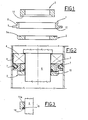
- the sealing device in question essentially comprises an inner friction ring 1; an outer friction ring 2 which is intended to bear, along its edge, against a face of the ring 1; and an annular spacer 3 which is intended to be disposed in the ring 1 and clamped between the ring 2 and the rolling element (normally, but not necessarily, a bearing 4) which must be protected.
- the friction ring 1 is of cylindrical internal shape and is provided on its outside with a kind of annular lip 5: an annular groove 6 provided with flared side walls is provided on the external surface of this ring 1, contiguous with the annular lip and on the side intended to be turned towards the bearing 4 in the assembly position.
- the annular lip 5 and the groove 6 define the housing intended to partially receive a seal 7 made of synthetic rubber, of the "0-ring seal" type.
- the lining 7 is intended to exert a sealed action on the bearing 4 and on the surface of the housing 8 in which the group is mounted.
- the outer friction ring 2 is of flattened cylindrical shape and has an inside diameter slightly larger than the diameter of the shaft 9 on which the bearing 4 is mounted.
- the face 2a of the ring 2 is intended to bear against the corresponding annular face 12 of the friction ring 1.
- This support will be provided by clamping elements, such as collars or adjustment nuts, mounted on the end part of the shaft 9 and not shown in the figures.
- the spacer 3 is of cylindrical shape and its internal diameter is equal to that of the ring 2.
- the spacer 3 On its face intended to bear against the ring 2, the spacer 3 is provided with an annular housing provided with a step 1 4 .
- This step defines, in collaboration with the ring 2, a groove intended to accommodate another packing 15 of the "0-ring seal" type.
- the lining 15 is of substantially smaller cross section than the lining 7 and, in the assembly position, is intended to exert a sealed action on the shaft 9.
- the spacer 3 also has axial dimensions slightly greater than those of the ring 1.
- the group formed by the rings 1 and 2 and the spacer 3, including the corresponding linings 7 and 15, constitutes the device forming the subject of the invention which is able to ensure a perfect seal for the protection of the rolling element 4.
- This device has a remarkably smaller axial size than that of traditional type radial steel sealing devices; practically the size is equal to that of conventional oil guards and therefore it does not the accommodation in group 4 should not be modified. This smaller footprint also leads to better use of the characteristics of group 4, which can thus work in a less cantilevered condition.
- the device in question does not require accessories for lateral thrusts and that it also performs the function of spacer.
- the rings 1 and 2 are preferably produced from steel of type 1 00 Cr 6, the spacer 3 from steel of type C 43.
- the surface 2a and the surface 12 of the rings 2 and 1 respectively, intended for mutual support are subjected to lapping operations.
- the housing 1 4 presented by the spacer 3 can be shaped as shown in Figure 3, that is to say that the wall 14a of the step 1 4 can be inclined so as to favor the thrust and therefore the seal of the lining 15 on the shaft 9.
- the materials used can be of any kind, shape and dimensions of any kind and size, as required.
Landscapes
- Engineering & Computer Science (AREA)
- General Engineering & Computer Science (AREA)
- Mechanical Engineering (AREA)
- Sealing Of Bearings (AREA)
- Sealing Devices (AREA)
- Rolling Contact Bearings (AREA)
Applications Claiming Priority (2)
| Application Number | Priority Date | Filing Date | Title |
|---|---|---|---|
| IT478085U | 1985-02-22 | ||
| ITBO1985U4780U IT8504780U1 (it) | 1985-02-22 | 1985-02-22 | Dispositivo di tenuta radiali, in acciaio per gruppi volventi. |
Publications (3)
| Publication Number | Publication Date |
|---|---|
| EP0192615A2 true EP0192615A2 (de) | 1986-08-27 |
| EP0192615A3 EP0192615A3 (en) | 1987-05-27 |
| EP0192615B1 EP0192615B1 (de) | 1989-05-24 |
Family
ID=11113675
Family Applications (1)
| Application Number | Title | Priority Date | Filing Date |
|---|---|---|---|
| EP86830032A Expired EP0192615B1 (de) | 1985-02-22 | 1986-02-12 | Radiale Stahlabdichtungsvorrichtung für Wälzlager |
Country Status (4)
| Country | Link |
|---|---|
| US (1) | US4645216A (de) |
| EP (1) | EP0192615B1 (de) |
| DE (1) | DE3663573D1 (de) |
| IT (1) | IT8504780U1 (de) |
Cited By (2)
| Publication number | Priority date | Publication date | Assignee | Title |
|---|---|---|---|---|
| FR2604498A1 (fr) * | 1986-09-30 | 1988-04-01 | Fives Cail Babcock | Dispositif d'etancheite pour le palier intermediaire d'un rouleau a plusieurs appuis |
| EP0328568A4 (en) * | 1987-07-08 | 1991-08-14 | Warman International Limited | Annular elastomeric slurry seal |
Families Citing this family (3)
| Publication number | Priority date | Publication date | Assignee | Title |
|---|---|---|---|---|
| EP0303769A3 (de) * | 1987-08-18 | 1989-10-25 | Balzers Aktiengesellschaft | Vorrichtung zur Übertragung von Drehbewegungen durch die Wand einer Vakuumkammer |
| US9275887B2 (en) | 2006-07-20 | 2016-03-01 | Applied Materials, Inc. | Substrate processing with rapid temperature gradient control |
| EP3267079B1 (de) * | 2016-07-08 | 2022-06-22 | Goodrich Actuation Systems Limited | Drehdichtungsanordnung |
Family Cites Families (9)
| Publication number | Priority date | Publication date | Assignee | Title |
|---|---|---|---|---|
| US31171A (en) * | 1861-01-22 | Improvement in sewinq-machine s | ||
| US2611671A (en) * | 1951-04-05 | 1952-09-23 | Deere Mfg Co | Fluid seal assembly |
| US2898134A (en) * | 1956-07-16 | 1959-08-04 | Benbow Mfg Co Inc | Interior diameter maintaining support for seal rings |
| US3476395A (en) * | 1967-11-09 | 1969-11-04 | Cornelius Co | Shaft seal assembly |
| US3656764A (en) * | 1970-08-31 | 1972-04-18 | William P Robinson | Drill bit seal assembly |
| US3717293A (en) * | 1971-06-21 | 1973-02-20 | Shamban & Co W S | Seal assembly |
| US3951783A (en) * | 1974-11-18 | 1976-04-20 | Caterpillar Tractor Co. | Face seal for spherical surface |
| US3987561A (en) * | 1975-11-03 | 1976-10-26 | Caterpillar Tractor Co. | Auger mounting for auger scraper |
| USRE31171E (en) | 1978-05-26 | 1983-03-08 | Textron, Inc. | Hydraulic piston rod seal |
-
1985
- 1985-02-22 IT ITBO1985U4780U patent/IT8504780U1/it unknown
-
1986
- 1986-02-12 DE DE8686830032T patent/DE3663573D1/de not_active Expired
- 1986-02-12 EP EP86830032A patent/EP0192615B1/de not_active Expired
- 1986-02-18 US US06/830,375 patent/US4645216A/en not_active Expired - Fee Related
Cited By (2)
| Publication number | Priority date | Publication date | Assignee | Title |
|---|---|---|---|---|
| FR2604498A1 (fr) * | 1986-09-30 | 1988-04-01 | Fives Cail Babcock | Dispositif d'etancheite pour le palier intermediaire d'un rouleau a plusieurs appuis |
| EP0328568A4 (en) * | 1987-07-08 | 1991-08-14 | Warman International Limited | Annular elastomeric slurry seal |
Also Published As
| Publication number | Publication date |
|---|---|
| EP0192615B1 (de) | 1989-05-24 |
| IT8504780U1 (it) | 1986-08-22 |
| IT8504780V0 (it) | 1985-02-22 |
| EP0192615A3 (en) | 1987-05-27 |
| US4645216A (en) | 1987-02-24 |
| DE3663573D1 (en) | 1989-06-29 |
Similar Documents
| Publication | Publication Date | Title |
|---|---|---|
| FR2493460A1 (fr) | Joint annulaire d'etancheite et de raclage a arret automatique pour verin pneumatique | |
| FR2522095A1 (fr) | Joint homocinetique | |
| EP0635651B1 (de) | Lageranordnung für eine rotierende Welle einer Scheibenwischeranlage | |
| EP0337893B1 (de) | Kassettendichtung | |
| FR2719095A1 (fr) | Dispositif pour l'assemblage de bagues de roulements. | |
| EP0173607A1 (de) | Nadellager, insbesondere Hülsenadellager mit verstärkter Dichtung | |
| FR2540955A1 (fr) | Dispositif d'etancheite pour une chambre formee entre des elements interne et externe coaxiaux rotatifs l'un par rapport a l'autre | |
| FR2528136A1 (fr) | Dispositif d'etancheite pour rendre etanche un roulement | |
| EP0192615B1 (de) | Radiale Stahlabdichtungsvorrichtung für Wälzlager | |
| FR2504231A3 (fr) | Joint d'etancheite comprenant deux levres dont l'une est axiale et l'autre radiale, ainsi qu'un labyrinthe | |
| FR2529988A1 (fr) | Garniture d'etancheite du type a labyrinthe, notamment pour des machines tournantes telles que pompes ou analogues | |
| FR2573502A1 (fr) | Joint d'etancheite a levre pour arbre tournant | |
| FR2701298A1 (fr) | Roulement à capteur d'informations perfectionné. | |
| FR2632572A1 (fr) | Fixation sur la jante des composants necessaires pour surveiller un pneumatique | |
| FR2560308A1 (fr) | Corps de palier en deux parties a graissage par circulation d'huile | |
| FR1464434A (fr) | Joint pour arbres, notamment pour arbres oscillants | |
| EP1382869B1 (de) | Dichtungsanordnung in einem Lager, insbesondere für eine Getriebeachse | |
| FR2556427A1 (fr) | Dispositif de liaison a bague de tolerance | |
| EP0571284B1 (de) | Kurbelwellendichtung für eine Verbrennungskraftmaschine, besonders für Fahrzeug | |
| FR2585790A1 (fr) | Ensemble palier de butee et joint d'etancheite | |
| FR2570145A1 (fr) | Mecanisme de roulement a garniture d'etancheite a anneaux de glissement | |
| CH625317A5 (en) | Universal joint | |
| FR2587772A1 (fr) | Douille de frottement pour joint d'etancheite a levre pourvue d'un dispositif interne assurant un blocage en rotation dans les deux sens et en axial sur l'arbre tournant, par frettage sectoriel d'un anneau ouvert sous l'action de vis de serrage | |
| FR2677727A1 (fr) | Joint d'etancheite de sortie d'arbre. | |
| FR2520469A1 (fr) | Joint frontal mecanique |
Legal Events
| Date | Code | Title | Description |
|---|---|---|---|
| PUAI | Public reference made under article 153(3) epc to a published international application that has entered the european phase |
Free format text: ORIGINAL CODE: 0009012 |
|
| AK | Designated contracting states |
Kind code of ref document: A2 Designated state(s): DE FR GB NL SE |
|
| PUAL | Search report despatched |
Free format text: ORIGINAL CODE: 0009013 |
|
| AK | Designated contracting states |
Kind code of ref document: A3 Designated state(s): DE FR GB NL SE |
|
| 17P | Request for examination filed |
Effective date: 19870527 |
|
| 17Q | First examination report despatched |
Effective date: 19880704 |
|
| GRAA | (expected) grant |
Free format text: ORIGINAL CODE: 0009210 |
|
| AK | Designated contracting states |
Kind code of ref document: B1 Designated state(s): DE FR GB NL SE |
|
| PG25 | Lapsed in a contracting state [announced via postgrant information from national office to epo] |
Ref country code: SE Effective date: 19890524 Ref country code: NL Effective date: 19890524 Ref country code: GB Effective date: 19890524 |
|
| REF | Corresponds to: |
Ref document number: 3663573 Country of ref document: DE Date of ref document: 19890629 |
|
| NLV1 | Nl: lapsed or annulled due to failure to fulfill the requirements of art. 29p and 29m of the patents act | ||
| GBV | Gb: ep patent (uk) treated as always having been void in accordance with gb section 77(7)/1977 [no translation filed] | ||
| PLBE | No opposition filed within time limit |
Free format text: ORIGINAL CODE: 0009261 |
|
| STAA | Information on the status of an ep patent application or granted ep patent |
Free format text: STATUS: NO OPPOSITION FILED WITHIN TIME LIMIT |
|
| 26N | No opposition filed | ||
| PGFP | Annual fee paid to national office [announced via postgrant information from national office to epo] |
Ref country code: FR Payment date: 19940228 Year of fee payment: 9 |
|
| PGFP | Annual fee paid to national office [announced via postgrant information from national office to epo] |
Ref country code: DE Payment date: 19940310 Year of fee payment: 9 |
|
| PG25 | Lapsed in a contracting state [announced via postgrant information from national office to epo] |
Ref country code: FR Effective date: 19951031 |
|
| PG25 | Lapsed in a contracting state [announced via postgrant information from national office to epo] |
Ref country code: DE Effective date: 19951101 |
|
| REG | Reference to a national code |
Ref country code: FR Ref legal event code: ST |