EP0192618A2 - Vorrichtung für eine motorisierte Säge - Google Patents
Vorrichtung für eine motorisierte Säge Download PDFInfo
- Publication number
- EP0192618A2 EP0192618A2 EP86850002A EP86850002A EP0192618A2 EP 0192618 A2 EP0192618 A2 EP 0192618A2 EP 86850002 A EP86850002 A EP 86850002A EP 86850002 A EP86850002 A EP 86850002A EP 0192618 A2 EP0192618 A2 EP 0192618A2
- Authority
- EP
- European Patent Office
- Prior art keywords
- saw blade
- support plate
- saw
- circular disc
- circular
- Prior art date
- Legal status (The legal status is an assumption and is not a legal conclusion. Google has not performed a legal analysis and makes no representation as to the accuracy of the status listed.)
- Withdrawn
Links
Images
Classifications
-
- B—PERFORMING OPERATIONS; TRANSPORTING
- B23—MACHINE TOOLS; METAL-WORKING NOT OTHERWISE PROVIDED FOR
- B23D—PLANING; SLOTTING; SHEARING; BROACHING; SAWING; FILING; SCRAPING; LIKE OPERATIONS FOR WORKING METAL BY REMOVING MATERIAL, NOT OTHERWISE PROVIDED FOR
- B23D49/00—Machines or devices for sawing with straight reciprocating saw blades, e.g. hacksaws
- B23D49/10—Hand-held or hand-operated sawing devices with straight saw blades
- B23D49/16—Hand-held or hand-operated sawing devices with straight saw blades actuated by electric or magnetic power or prime movers
-
- Y—GENERAL TAGGING OF NEW TECHNOLOGICAL DEVELOPMENTS; GENERAL TAGGING OF CROSS-SECTIONAL TECHNOLOGIES SPANNING OVER SEVERAL SECTIONS OF THE IPC; TECHNICAL SUBJECTS COVERED BY FORMER USPC CROSS-REFERENCE ART COLLECTIONS [XRACs] AND DIGESTS
- Y10—TECHNICAL SUBJECTS COVERED BY FORMER USPC
- Y10T—TECHNICAL SUBJECTS COVERED BY FORMER US CLASSIFICATION
- Y10T83/00—Cutting
- Y10T83/869—Means to drive or to guide tool
- Y10T83/8878—Guide
- Y10T83/8881—With anti-friction means
Definitions
- the present invention relates to a device for a motorized saw of the kind wherein the saw is built up from a reciprocating toothed saw blade and a relative to this stationary support plate.
- An object of the present invention is to provide a device for such saws arranged such that the friction can be diminished and therefore a power-requiring motor can be used which has a small weight.
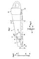
- a saw guide bar 11 attached to a motor casing 10.
- the casing encloses a combustion or electrical motor.
- the saw guide bar consists of a support plate 12 and a reciprocating toothed saw blade 13 slidably arranged thereto.
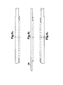
- the saw blade 13 consists of three toothed portions secured to each other.
- the saw blade 13 is arranged so that the direct contact between the support plate 12 and the saw blade 13 only serves to stop the sideways bending of the saw blade 13 while the feed force is carried by one or more circular discs 14, each of which is loosely laid into an elongated recess 15 in the support plate 12.
- the diameter of each disc 14 is about 100 times the width thereof.
- the saw blade 13 is connected to the motor by means of levers 23.
- the levers 23 and co-operating portions in the front end of the saw keep the blade from falling off the saw guide bar 11.
- the support plate 12 is built up from three layers, the mid layer 16 of which is equal in thickness as or somewhat broader than the side layers 17 and 18 situated on each side thereof.
- the mid layer has a portion projecting from the support plate which is received in a groove 19 in the saw blade 13.
- the co-operating portions consist of projections 24, 25 extending mainly perpencidularly to the longitudinal direction of the blade 13 and an extended portion 26 of the saw blade 13. These projections form units with respective associated side layer 17, 18.
- the projections 24, 25 enclose a spacing which slidably receives the portion 26 without causing any additional frictional force during cutting.
- Each circular disc 14 is thinner than the mid layer 16 and is loosely laid into the recess 15 which is bordered by a straight contour part 20, parallel with the saw blade 13, and circular end portions 21 and 22 such that the circular disc or circular discs 14 may roll forwards and backwards therein.
- the saw blade 13 and the support plate 12 have mainly equal thickness.
- the diameter of the circular blank 14 is so much larger than the length of the straight part 20 that the circular blank does not fall out from the recess 15 when the saw blade 13 is removed for replacement or sharpening of the teeth.
- Each circular disc is made with a diameter which exceeds half of the length of the stroke.
- the circular disc 14 can, with a light bending, because it is made thin and flexible, be brought obliquely into the recess 15 at its broader part.
- the depth of the recess 15 should be slightly less than the diameter of the circular disc 14.
- the recess 15 is opened towards the outside by means of a number of holes 27 in the side layers 17, 18.
- the holes 27 allow for cut material that has entered the recess 15 to be removed therefrom.
- Figs. 4A-4C show the three parts of the saw blade.
- the present invention relates to a device for a motorized saw which may be driven by a motor having small power and weight and constructed such that the saw blade is mounted to the support plate in a most economic manner in terms of friction. This is achieved by having the center of the disc movable relative to the saw blade as well as to the support plate.
Landscapes
- Engineering & Computer Science (AREA)
- Mechanical Engineering (AREA)
- Sawing (AREA)
- Road Repair (AREA)
- Mechanical Treatment Of Semiconductor (AREA)
Applications Claiming Priority (2)
| Application Number | Priority Date | Filing Date | Title |
|---|---|---|---|
| SE8500656 | 1985-02-13 | ||
| SE8500656A SE8500656L (sv) | 1985-02-13 | 1985-02-13 | Anordning vid motordriven sag |
Publications (2)
| Publication Number | Publication Date |
|---|---|
| EP0192618A2 true EP0192618A2 (de) | 1986-08-27 |
| EP0192618A3 EP0192618A3 (de) | 1987-08-26 |
Family
ID=20359097
Family Applications (1)
| Application Number | Title | Priority Date | Filing Date |
|---|---|---|---|
| EP86850002A Withdrawn EP0192618A3 (de) | 1985-02-13 | 1986-01-09 | Vorrichtung für eine motorisierte Säge |
Country Status (4)
| Country | Link |
|---|---|
| US (1) | US4665618A (de) |
| EP (1) | EP0192618A3 (de) |
| JP (1) | JPS61185401A (de) |
| SE (1) | SE8500656L (de) |
Cited By (2)
| Publication number | Priority date | Publication date | Assignee | Title |
|---|---|---|---|---|
| GB2180791B (en) * | 1985-09-27 | 1990-01-10 | Black & Decker Inc | Improvements in and relating to power saws |
| EP4552780A1 (de) * | 2023-11-13 | 2025-05-14 | Hilti Aktiengesellschaft | Hin- und hergehende säge |
Families Citing this family (5)
| Publication number | Priority date | Publication date | Assignee | Title |
|---|---|---|---|---|
| GB8523425D0 (en) * | 1985-09-23 | 1985-10-30 | Black & Decker Inc | Power tools |
| EP0267973B1 (de) * | 1986-11-11 | 1992-02-12 | Black & Decker Inc. | Kraftgetriebene Säge, insbesondere elektromotorisch angetriebene Säge |
| EP0267311A1 (de) * | 1986-11-11 | 1988-05-18 | Black & Decker Inc. | Sägeblatt für eine Säge mit zwei nebeneinander, parallel zueinander angeordneten, gegensinnig hin- und herbewegbaren Sägeblättern |
| US9101992B2 (en) * | 2013-11-18 | 2015-08-11 | Ningbo Gemay Industry Co., Inc | Reciprocating saw blade assembly |
| US9498832B2 (en) * | 2013-11-18 | 2016-11-22 | Richpower Industries Inc. | Reciprocating saw blade assembly |
Family Cites Families (9)
| Publication number | Priority date | Publication date | Assignee | Title |
|---|---|---|---|---|
| US1537980A (en) * | 1922-06-09 | 1925-05-19 | Louis A G Asselin | Drag saw |
| US1829079A (en) * | 1930-06-17 | 1931-10-27 | James A Young | Meat saw |
| US1838125A (en) * | 1931-08-20 | 1931-12-29 | Wirtz William | Sawing implement |
| US2895514A (en) * | 1954-08-19 | 1959-07-21 | John W Wright | Portable reciprocating power saw |
| US3064698A (en) * | 1959-08-28 | 1962-11-20 | Thomas Industries Inc | Anti-friction blade and guide |
| US3537490A (en) * | 1968-09-05 | 1970-11-03 | Beaird Poulan Inc | Reciprocating blade saw |
| US3748738A (en) * | 1971-12-13 | 1973-07-31 | Wells Manuf Corp | Support means for reciprocating saw blade |
| US4031622A (en) * | 1975-10-28 | 1977-06-28 | Wells Manufacturing Corporation | Portable power driven implement |
| DE3329824A1 (de) * | 1983-01-25 | 1984-08-02 | Frank, Helmut | Motorsaege |
-
1985
- 1985-02-13 SE SE8500656A patent/SE8500656L/ not_active Application Discontinuation
-
1986
- 1986-01-09 EP EP86850002A patent/EP0192618A3/de not_active Withdrawn
- 1986-02-05 US US06/826,256 patent/US4665618A/en not_active Expired - Fee Related
- 1986-02-12 JP JP61026988A patent/JPS61185401A/ja active Pending
Cited By (3)
| Publication number | Priority date | Publication date | Assignee | Title |
|---|---|---|---|---|
| GB2180791B (en) * | 1985-09-27 | 1990-01-10 | Black & Decker Inc | Improvements in and relating to power saws |
| EP4552780A1 (de) * | 2023-11-13 | 2025-05-14 | Hilti Aktiengesellschaft | Hin- und hergehende säge |
| WO2025103658A1 (en) * | 2023-11-13 | 2025-05-22 | Hilti Aktiengesellschaft | Reciprocating saw |
Also Published As
| Publication number | Publication date |
|---|---|
| SE8500656L (sv) | 1986-08-14 |
| US4665618A (en) | 1987-05-19 |
| SE8500656D0 (sv) | 1985-02-13 |
| EP0192618A3 (de) | 1987-08-26 |
| JPS61185401A (ja) | 1986-08-19 |
Similar Documents
| Publication | Publication Date | Title |
|---|---|---|
| US4334356A (en) | Anti-mar base for saber- and bayonet-type saws and the like | |
| US4353165A (en) | Saw | |
| US4969270A (en) | Power driven saw with reciprocating saw blades | |
| US4265285A (en) | Combination cross and rip cut handsaw | |
| CA1298531C (en) | Saw blade for power operated saw | |
| US6553669B2 (en) | Pipe cutter and method of cutting pipe | |
| US4665618A (en) | Device for a motorized saw | |
| GB2218376A (en) | Sawblades for a power saw with reciprocating blades | |
| US4893411A (en) | Power sawblades for abrasive materials | |
| US4742743A (en) | Radial saw accessory for preventing sawdust buildup | |
| US4989489A (en) | Brush cutting blade | |
| US4619172A (en) | Cutting saw for grinding solid materials | |
| US2770267A (en) | All purpose saw blade | |
| US4821414A (en) | Swing saw for cutting metal conduit | |
| EP0569343B2 (de) | Sägeblatt | |
| US3748738A (en) | Support means for reciprocating saw blade | |
| CA2308656A1 (en) | Saw for cutting hard materials | |
| DE59103108D1 (de) | Vorrichtung zum Trennen oder Schlitzen eines starren Schnittgutes, insbesondere Holz. | |
| CN1293102A (zh) | 线锯,尤其是精切锯 | |
| EP0765208B1 (de) | Vorrichtung zum herstellen von seitlich gekrümmten holzwollefasern | |
| SU1544555A1 (ru) | Ручна пила дл резани слоистых материалов | |
| GB1460773A (en) | Saws | |
| EP0205245A1 (de) | Werkzeuge mit gezahnten Schneiden | |
| EP0940209A3 (de) | Gehrungssäge | |
| EP1240965B1 (de) | Holzsägeblatt |
Legal Events
| Date | Code | Title | Description |
|---|---|---|---|
| PUAI | Public reference made under article 153(3) epc to a published international application that has entered the european phase |
Free format text: ORIGINAL CODE: 0009012 |
|
| AK | Designated contracting states |
Kind code of ref document: A2 Designated state(s): DE FR GB SE |
|
| PUAL | Search report despatched |
Free format text: ORIGINAL CODE: 0009013 |
|
| AK | Designated contracting states |
Kind code of ref document: A3 Designated state(s): DE FR GB SE |
|
| 17P | Request for examination filed |
Effective date: 19880405 |
|
| 17Q | First examination report despatched |
Effective date: 19890726 |
|
| STAA | Information on the status of an ep patent application or granted ep patent |
Free format text: STATUS: THE APPLICATION IS DEEMED TO BE WITHDRAWN |
|
| 18D | Application deemed to be withdrawn |
Effective date: 19910801 |
|
| RIN1 | Information on inventor provided before grant (corrected) |
Inventor name: LEINI, ARVO |