EP0192808A2 - Dispositif d'ajustement d'un système à compression d'impulsions comportant plusieurs canaux - Google Patents
Dispositif d'ajustement d'un système à compression d'impulsions comportant plusieurs canaux Download PDFInfo
- Publication number
- EP0192808A2 EP0192808A2 EP85107347A EP85107347A EP0192808A2 EP 0192808 A2 EP0192808 A2 EP 0192808A2 EP 85107347 A EP85107347 A EP 85107347A EP 85107347 A EP85107347 A EP 85107347A EP 0192808 A2 EP0192808 A2 EP 0192808A2
- Authority
- EP
- European Patent Office
- Prior art keywords
- signal
- pulse
- control
- arrangement
- difference signal
- Prior art date
- Legal status (The legal status is an assumption and is not a legal conclusion. Google has not performed a legal analysis and makes no representation as to the accuracy of the status listed.)
- Withdrawn
Links
Images
Classifications
-
- G—PHYSICS
- G01—MEASURING; TESTING
- G01S—RADIO DIRECTION-FINDING; RADIO NAVIGATION; DETERMINING DISTANCE OR VELOCITY BY USE OF RADIO WAVES; LOCATING OR PRESENCE-DETECTING BY USE OF THE REFLECTION OR RERADIATION OF RADIO WAVES; ANALOGOUS ARRANGEMENTS USING OTHER WAVES
- G01S13/00—Systems using the reflection or reradiation of radio waves, e.g. radar systems; Analogous systems using reflection or reradiation of waves whose nature or wavelength is irrelevant or unspecified
- G01S13/02—Systems using reflection of radio waves, e.g. primary radar systems; Analogous systems
- G01S13/06—Systems determining position data of a target
- G01S13/42—Simultaneous measurement of distance and other co-ordinates
- G01S13/44—Monopulse radar, i.e. simultaneous lobing
- G01S13/4436—Monopulse radar, i.e. simultaneous lobing with means specially adapted to maintain the same processing characteristics between the monopulse signals
-
- G—PHYSICS
- G01—MEASURING; TESTING
- G01S—RADIO DIRECTION-FINDING; RADIO NAVIGATION; DETERMINING DISTANCE OR VELOCITY BY USE OF RADIO WAVES; LOCATING OR PRESENCE-DETECTING BY USE OF THE REFLECTION OR RERADIATION OF RADIO WAVES; ANALOGOUS ARRANGEMENTS USING OTHER WAVES
- G01S13/00—Systems using the reflection or reradiation of radio waves, e.g. radar systems; Analogous systems using reflection or reradiation of waves whose nature or wavelength is irrelevant or unspecified
- G01S13/02—Systems using reflection of radio waves, e.g. primary radar systems; Analogous systems
- G01S13/06—Systems determining position data of a target
- G01S13/08—Systems for measuring distance only
- G01S13/10—Systems for measuring distance only using transmission of interrupted, pulse modulated waves
- G01S13/26—Systems for measuring distance only using transmission of interrupted, pulse modulated waves wherein the transmitted pulses use a frequency- or phase-modulated carrier wave
- G01S13/28—Systems for measuring distance only using transmission of interrupted, pulse modulated waves wherein the transmitted pulses use a frequency- or phase-modulated carrier wave with time compression of received pulses
- G01S13/282—Systems for measuring distance only using transmission of interrupted, pulse modulated waves wherein the transmitted pulses use a frequency- or phase-modulated carrier wave with time compression of received pulses using a frequency modulated carrier wave
Definitions
- the present invention relates to an arrangement for controlling a multi-channel pulse compression system according to the preamble of patent claim 1.
- the phase and the amplitude of the signal of a channel must be regulated in relation to the transmission behavior of the signal of a channel chosen as a reference in order to achieve the desired accuracy, which in such systems, in particular when determining angles, is highly dependent on the synchronism behavior of the receiving channels .
- the known control methods do not meet the requirements that arise in systems with a very short pulse duration.
- the invention shows a way to create an arrangement for regulating a multi-channel, very broadband, high-resolution pulse compression system that works with an extremely short pulse duration.
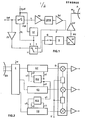
- the expander according to FIG. 1 has an expansion filter OFW which has an intermediate frequency signal Szf applied to it on the input side via a pulse modulator PM.
- the expansion filter OFW which can be followed by a pulse amplifier PV and / or a signal amplifier SV, is connected to the input of a frequency converter FU via the series connection of a high-frequency gate G and a limiter B.
- the output of the converter FU is connected to a transmission antenna A via a power amplifier LV.
- a high-frequency switch H is optionally inserted in series with an additional amplifier ZV between the input of the pulse modulator PM and the input of the gate G.
- the pulse modulator PM and the changeover switch H can be switched on or off by the output signal St of a control circuit ST which, for example, comprises a frequency plate 1 to N for a pulse repetition frequency signal Sprf.
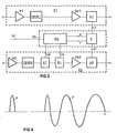
- the pulse modulator PM controlled by the signal Sprf leaves only a single pulse or a short pulse packet x (FIG. 4) from the continuous wave signal Szf - i.e. a carrier-frequency, non-frequency-modulated pulse (burst) - get through, provided that it is switched on by the signal St.
- the expansion filter OFW which comprises a dispersive surface wave or SAW delay line, expands the signal x such that it appears on the output side as a frequency-modulated wave y (FIG. 4), the signal duration of which is many times longer than the pulse width of the signal x.
- the signal y is then converted to a high-frequency carrier in the microwave range, amplified and emitted.
- a tell w is coupled out on the antenna A from the emitted signal.
- the gate G also has the task of somewhat limiting the duration of the signal y in order to cut off oscillations and decay.
- the three-channel put compression system according to FIG. 2 has a microwave receiver E connected to an antenna EA, which is connected on the output side to a demodulator D via three channels K1, K2, K3 and the signal w is applied to the input side.
- the system also includes two control circuits RS2 and RS3, whose output signals u2, v2 and u3, v3 are used to control channels K2 and K3, the first control circuit RS2 on the input side having branched signals z1 and z2 taken from channels K1 and K2 and the second control circuit RS3 is supplied with the signal z1 and a branched signal z3 taken from the channel K3.
- the mode of operation of the system according to FIG. 2 is explained with the aid of the arrangement shown in FIG. 3.
- the channel K1 comprises the series connection of an amplifier V1, a compressor OFW1, a further amplifier VA1 and a first coupler A1, which is connected to the first input of the demodulator D (FIG. 2) controlled by a local signal (S) (local oscillator signal) .
- the channel K2 consists of the series connection of an amplifier V2, a second compressor OFW2, a controlled attenuator AT, a controlled phase shifter PH, a further amplifier VA2 and a second decoupler A2, which is connected to the second output of the demodulator D (FIG. 2) is.
- the control circuit RS (FIG. 3) there is also a comparator K, which is supplied with the second output signal z1 of the first outcoupler A1 on the input side and with the second output signal z2 of the second outcoupler A2 on the one hand and outputs two voltage error signals u and v, respectively separate inputs of a controller RG are supplied.
- the controller RG which each has an interrogation and hold circuit controlled by a signal St ', each with a controlled system, delivers a control signal u2 or v2, which are used to control the attenuator AT or the phase shifter PH.
- An expanded signal received via the antenna EA (FIG. 2) is compressed by the compressor OFW1 (FIG. 3), which comprises a dispersive surface wave delay line, and passed on via the coupler A1 to the demodulator D (FIG. 2), which also has a quadrature Demodulator could be.
- the compressor OFW1 (FIG. 3) occasionally reaches a signal that got through the switch H (FIG. 1) instead of the expander OFW and therefore does not represent a frequency-modulated wave, it is transmitted by the compressor OFW1 (FIG. 3) not compressed since it can only compress predetermined frequency modulated waves.
- a signal component z1 is then decoupled from such a signal in the decoupler A1.
- the second channel K2 in which the compressor OFW2 can also only compress frequency-modulated waves and the elements AT and PH only effect an amplitude or phase control.
- the fault voltage signals are queried and stored just when the signal St 'is present, which has the same repetition frequency as the signal St. Compared to signal St, however, signal St 'can be delayed and have a different pulse width.
- the comparator K could contain devices that allow it to evaluate only waves that are not frequency-modulated.
- the signals u2 and v2 emitted by the controller RG regulate the second channel K2 in such a way that the signals u and v go towards zero on average. Since the transmission power does not change according to this method, there are no problems with the dimensioning of the transmitter in relation to its performance.
- the invention is not limited to two channels, but can be used in the same way for three or more channels, for example by the signals u3 and v3 (FIG. 2) each regulating a further attenuator or a phase shifter in a corresponding manner. (Otherwise, for example (FIG. 3), the attenuator AT could otherwise also be inserted between the output of the compressor OFW1 and the input of the amplifier VA1 in channel 1. Instead of the attenuator AT, regulated amplifiers could also be used.
- the arrangement according to the invention can also be used in a radar device in which a single antenna with a transmitter-receiver unit is present, because the operation of the arrangement is not influenced thereby.
- Radar devices of this type are known, for example, from CH-PS 592 887 or EP-PS 0 027 122.
- the arrangement according to the invention enables very precise control in radar devices that work with short pulses, and has the advantage in radar devices that work with relatively long pulses that the control can reduce the error after just one pulse.
Landscapes
- Engineering & Computer Science (AREA)
- Radar, Positioning & Navigation (AREA)
- Remote Sensing (AREA)
- Computer Networks & Wireless Communication (AREA)
- Physics & Mathematics (AREA)
- General Physics & Mathematics (AREA)
- Signal Processing (AREA)
- Radar Systems Or Details Thereof (AREA)
Applications Claiming Priority (2)
| Application Number | Priority Date | Filing Date | Title |
|---|---|---|---|
| CH919/85 | 1985-02-28 | ||
| CH91985 | 1985-02-28 |
Publications (2)
| Publication Number | Publication Date |
|---|---|
| EP0192808A2 true EP0192808A2 (fr) | 1986-09-03 |
| EP0192808A3 EP0192808A3 (fr) | 1988-07-13 |
Family
ID=4198225
Family Applications (1)
| Application Number | Title | Priority Date | Filing Date |
|---|---|---|---|
| EP85107347A Withdrawn EP0192808A3 (fr) | 1985-02-28 | 1985-06-13 | Dispositif d'ajustement d'un système à compression d'impulsions comportant plusieurs canaux |
Country Status (3)
| Country | Link |
|---|---|
| US (1) | US4674104A (fr) |
| EP (1) | EP0192808A3 (fr) |
| IL (1) | IL77994A (fr) |
Families Citing this family (2)
| Publication number | Priority date | Publication date | Assignee | Title |
|---|---|---|---|---|
| US5258997A (en) * | 1992-05-27 | 1993-11-02 | Voyager Technologies, Inc. | Spread spectrum apparatus |
| DE19957128C1 (de) * | 1999-11-26 | 2001-08-16 | Siemens Audiologische Technik | Verfahren zur Pegelbegrenzung in einem digitalen Hörhilfegerät sowie digitales Hörhilfegerät |
Family Cites Families (15)
| Publication number | Priority date | Publication date | Assignee | Title |
|---|---|---|---|---|
| US2784400A (en) * | 1945-09-14 | 1957-03-05 | Albert D Ehrenfried | Simultaneous lobing with monitored dual receiver |
| US2977588A (en) * | 1949-03-31 | 1961-03-28 | Rca Corp | Radar systems with gain equalization circuits |
| US3303497A (en) * | 1963-03-28 | 1967-02-07 | Charles F Chubb | Time expansion radar |
| FR1580104A (fr) * | 1963-10-03 | 1969-09-05 | ||
| US4196435A (en) * | 1967-08-21 | 1980-04-01 | The United States Of America As Represented By The Secretary Of The Air Force | Radar pulse phase code system |
| US3618095A (en) * | 1969-11-10 | 1971-11-02 | Bell Telephone Labor Inc | Automatic equalizer for chirp radar system |
| US3862371A (en) * | 1970-02-24 | 1975-01-21 | Hans Neustadt | Message transmission system with pulse compression |
| US4096478A (en) * | 1971-07-06 | 1978-06-20 | International Telephone And Telegraph Corporation | Intra-pulse MTI system with range ambiguity suppression |
| US3883871A (en) * | 1973-03-12 | 1975-05-13 | Randolph G Moore | Method and modulation system for ambiguity reduction in pulsed radar |
| GB1424026A (en) * | 1973-11-13 | 1976-02-04 | Marconi Co Ltd | Radar systems |
| US3921173A (en) * | 1974-08-14 | 1975-11-18 | Us Navy | Accurate normalization for a monopulse radar |
| US4161732A (en) * | 1976-11-12 | 1979-07-17 | Westinghouse Electric Corp. | Gated pulse compression radar |
| GB2044571A (en) * | 1979-03-17 | 1980-10-15 | Marconi Co Ltd | Pulse radar system |
| US4427982A (en) * | 1981-04-28 | 1984-01-24 | The United States Of America As Represented By The Secretary Of The Navy | Radar clutter reduction by use of frequency-diverse, wideband pulse-compression waveforms |
| US4472717A (en) * | 1982-03-19 | 1984-09-18 | The United States Of America As Represented By The Secretary Of The Army | Intrapulse polarization agile radar system (IPAR) |
-
1985
- 1985-06-13 EP EP85107347A patent/EP0192808A3/fr not_active Withdrawn
-
1986
- 1986-02-19 US US06/830,765 patent/US4674104A/en not_active Expired - Fee Related
- 1986-02-26 IL IL77994A patent/IL77994A/xx unknown
Also Published As
| Publication number | Publication date |
|---|---|
| IL77994A0 (en) | 1986-08-31 |
| US4674104A (en) | 1987-06-16 |
| IL77994A (en) | 1990-07-26 |
| EP0192808A3 (fr) | 1988-07-13 |
Similar Documents
| Publication | Publication Date | Title |
|---|---|---|
| DE2945331C2 (de) | Vorrichtung in einer Signal-oder Datenverarbeitungsanlage zur Einstellung einer Signalverarbeitungsschaltung | |
| DE3107444C2 (de) | Hochauflösendes kohärentes Pulsradar | |
| DE2918857C2 (fr) | ||
| DE69421364T2 (de) | Verfahren zum Prüfen eines Sender-Empfängers und Basisstation einer Zeitmultiplexfunkkommunikationsanlage | |
| DE10027064B4 (de) | Doppler-Impulsradarvorrichtung | |
| DE2812575C2 (de) | Phasengesteuertes Antennenfeld | |
| EP1708387B1 (fr) | Appareil récepteur avec diversité d'antennes pour des signaux radio numériques modulés en MPSK pour des voitures | |
| EP0355336B1 (fr) | Système radar pour la détermination de la position de deux ou plusieurs objets | |
| DE3600280A1 (de) | Kombinierte mehrfach-empfangsvorrichtung | |
| DE2817836B2 (de) | Verfahren zur Mehrfachübertragung digitaler Signale sowie Einrichtung zur Durchführung eines solchen Verfahrens | |
| DE2413995B2 (de) | Impuls-Abfrage/Antwort-System zur Entfernungsbestimmung mit Steuerung des Antwortsignal-Sendezeitpunktes | |
| DE2507282C3 (de) | Regelsystem zur Wiederherstellung der Orthogonalität zweier orthogonal polarisiert gesendeter und im Funkfeld verkoppelter Signale | |
| DE2505723C3 (de) | Einrichtung zur Überwachung der von einer DVOR-Bodenstation abgestrahlten Trägerfrequenz- und Seitenbandsignale | |
| EP0192808A2 (fr) | Dispositif d'ajustement d'un système à compression d'impulsions comportant plusieurs canaux | |
| EP0220360B1 (fr) | Système expanseur pour signaux impulsionnels | |
| DE2728773C2 (de) | Funk-Fernsteuereinrichtung | |
| DE1963422C3 (de) | Verzweigungs- oder Synthesegerät für Mehrfrequenz-Fernmeldesysteme | |
| DE69421212T2 (de) | Verstärker mit sequentieller Wirkungsweise | |
| DE3324693A1 (de) | Verfahren zur zweiweg-hochfrequenz-laufzeitmessung | |
| DE4014407C2 (fr) | ||
| DE2033017A1 (de) | Vorrichtung zum Empfang mehrerer Eingangssignale gleicher Frequenz | |
| DE2643967C2 (de) | Empfangsseitige Einrichtung für eine mit Raumdiversity arbeitende Richtfunkstrecke | |
| DE1591054B2 (de) | Nachrichtenempfaenger fuer frequenzmodulierte signale | |
| DE3037265C2 (de) | Sendegerät zur Hochfrequenz-Informationsübermittlung | |
| DE977595C (de) | Verfahren zur zeitlichen Kompression der Echoimpulse eines Radargeraets sowie Radargeraet zur Anwendung des Verfahrens |
Legal Events
| Date | Code | Title | Description |
|---|---|---|---|
| PUAI | Public reference made under article 153(3) epc to a published international application that has entered the european phase |
Free format text: ORIGINAL CODE: 0009012 |
|
| 17P | Request for examination filed |
Effective date: 19850627 |
|
| AK | Designated contracting states |
Kind code of ref document: A2 Designated state(s): CH DE FR GB IT LI NL SE |
|
| PUAL | Search report despatched |
Free format text: ORIGINAL CODE: 0009013 |
|
| AK | Designated contracting states |
Kind code of ref document: A3 Designated state(s): CH DE FR GB IT LI NL SE |
|
| 17Q | First examination report despatched |
Effective date: 19900904 |
|
| STAA | Information on the status of an ep patent application or granted ep patent |
Free format text: STATUS: THE APPLICATION IS DEEMED TO BE WITHDRAWN |
|
| 18D | Application deemed to be withdrawn |
Effective date: 19920310 |
|
| RIN1 | Information on inventor provided before grant (corrected) |
Inventor name: BAECHTIGER, ROLF |