EP0192873A2 - Vorrichtung zur Feineinstellung der Formwalzen eines Präzisionswalzwerkes - Google Patents
Vorrichtung zur Feineinstellung der Formwalzen eines Präzisionswalzwerkes Download PDFInfo
- Publication number
- EP0192873A2 EP0192873A2 EP19850306193 EP85306193A EP0192873A2 EP 0192873 A2 EP0192873 A2 EP 0192873A2 EP 19850306193 EP19850306193 EP 19850306193 EP 85306193 A EP85306193 A EP 85306193A EP 0192873 A2 EP0192873 A2 EP 0192873A2
- Authority
- EP
- European Patent Office
- Prior art keywords
- rollers
- rolling mill
- precision rolling
- shafts
- roller
- Prior art date
- Legal status (The legal status is an assumption and is not a legal conclusion. Google has not performed a legal analysis and makes no representation as to the accuracy of the status listed.)
- Withdrawn
Links
- 238000005096 rolling process Methods 0.000 title claims abstract description 19
- 229910000831 Steel Inorganic materials 0.000 claims abstract description 10
- 239000010959 steel Substances 0.000 claims abstract description 10
- 239000004429 Calibre Substances 0.000 description 5
- 238000003825 pressing Methods 0.000 description 4
- 230000007246 mechanism Effects 0.000 description 3
- 230000007812 deficiency Effects 0.000 description 1
- 230000000593 degrading effect Effects 0.000 description 1
- 230000001771 impaired effect Effects 0.000 description 1
- 238000003754 machining Methods 0.000 description 1
- 238000000034 method Methods 0.000 description 1
Images


Classifications
-
- B—PERFORMING OPERATIONS; TRANSPORTING
- B21—MECHANICAL METAL-WORKING WITHOUT ESSENTIALLY REMOVING MATERIAL; PUNCHING METAL
- B21B—ROLLING OF METAL
- B21B39/00—Arrangements for moving, supporting, or positioning work, or controlling its movement, combined with or arranged in, or specially adapted for use in connection with, metal-rolling mills
- B21B39/14—Guiding, positioning or aligning work
- B21B39/16—Guiding, positioning or aligning work immediately before entering or after leaving the pass
- B21B39/165—Guides or guide rollers for rods, bars, rounds, tubes ; Aligning guides
-
- B—PERFORMING OPERATIONS; TRANSPORTING
- B21—MECHANICAL METAL-WORKING WITHOUT ESSENTIALLY REMOVING MATERIAL; PUNCHING METAL
- B21B—ROLLING OF METAL
- B21B2273/00—Path parameters
- B21B2273/22—Aligning on rolling axis, e.g. of roll calibers
-
- B—PERFORMING OPERATIONS; TRANSPORTING
- B21—MECHANICAL METAL-WORKING WITHOUT ESSENTIALLY REMOVING MATERIAL; PUNCHING METAL
- B21B—ROLLING OF METAL
- B21B31/00—Rolling stand structures; Mounting, adjusting, or interchanging rolls, roll mountings, or stand frames
- B21B31/16—Adjusting or positioning rolls
- B21B31/18—Adjusting or positioning rolls by moving rolls axially
-
- B—PERFORMING OPERATIONS; TRANSPORTING
- B21—MECHANICAL METAL-WORKING WITHOUT ESSENTIALLY REMOVING MATERIAL; PUNCHING METAL
- B21B—ROLLING OF METAL
- B21B31/00—Rolling stand structures; Mounting, adjusting, or interchanging rolls, roll mountings, or stand frames
- B21B31/16—Adjusting or positioning rolls
- B21B31/20—Adjusting or positioning rolls by moving rolls perpendicularly to roll axis
- B21B31/22—Adjusting or positioning rolls by moving rolls perpendicularly to roll axis mechanically, e.g. by thrust blocks, inserts for removal
- B21B31/26—Adjusting eccentrically-mounted roll bearings
Definitions
- This invention relates to a precision rolling mill which comprises a pair of forming rollers which cooperate to carry out finishing action on rolled steel strip, in which a fine adjustment arrangement is provided to enable the axial alignment of the rollers to be adjusted in a final finish line for rolling steel strips.
- the present invention has therefore been developed primarily with a view to providing an adjustment device for a forming roller in a precision rolling mill, which can reliably adjust the required amount of axial movement of the forminc roller with a high precision, whereby the deficiencies c existing equipment can be overcome, and improvement in rolling product produced by the rolling mill obtained, particularly the out-of-roundness of wire rod and steel bar products often supplied with existing equipment.
- a precision rolling mill comprising a pair of forming rollers which cooperate to carry out finishing action on rolled steel strip, mounting shafts on which the rollers are mounted, and a pair of threaded adjusters engaging one on either side of each roller in order to enable the rollers to be adjusted axially relative to each other so as to bring them into alignment for a finishing action, characterised in that a reduction gear drive is coupled with each of the threaded adjusters to enable precise axial adjustment of the rollers.
- a pair of eccentric shafts 2a,2b have forming rollers la,lb thereon, and the shafts are mounted in a guide box 32 so as to be movable in an axial direction.
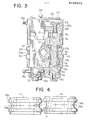
- the rollers la,lb are rotatable on the respective eccentric shafts, as shown in Figure 3 for roller lb, via sleeve or bush 14b and bearings 13b.
- Supporting shafts 3a,3b are integrally formed coaxially with the eccentric shafts 2a,2b on their upper ends.
- the axes or centres of the eccentric shafts 2a,2b are spaced eccentrically at a required distance from those of the supporting shafts 3a,3b.
- adjusting screws 17a,17b that press the supporting shafts 3a,3b in an axial direction.
- adjusting screws 6a,6b that press the eccentric shafts 2a,2b in an axial direction.
- the adjusting screws 17a,17b can be interlocked for operation by associated worm/worm wheel drive mechanisms 16a,15a,18a and 16b,15b,18b respectively in the upper gear case 23, and the adjusting screws 6a and 6b can be operated by associated worm/worm wheel drive mechanisms 16a,5a,7a and 16b,5b,7b respectively in the lower gear case 28. These worm mechanisms are described in more detail below.
- Worms 15a,15b are integrally formed with worm shafts 16a,16b provided in the upper gear case 23 and are in meshing relation with the worm wheels 18a,18b, which form the heads of adjusting screws 17a and 17b respectively. For this reason, the turning effort of worm shafts 16a,16b, when they are rotated, is imparted through worms 15a,16b to worm wheels 18a,180, which an turn are rotated at reduced speed as a first stage, subsequently turning the screw shanks 19a,19b for adjusting the screws 17a,17b.
- worms 5a,5b which are integrally formed with the worm shafts 16a,16b provided in the lower gear Merrise 25, transmit turning effort to the worm wheels 7a,7b of adjusting screws 6a,6b, causing the pressing parts 9a,9b above the wheels to move in vertical directions, and when the pressing parts move up, tne eccentric shafts 2a,2b are made to move axially in a small amount.
- 21a is a lock bolt for fixing the worm shafts 16a,16b.
- the upper gear case 23 is fixed on the upper portion of a guide box 32 using 3 hexagonal bolts 24.
- 26 is a case cover which is fixed in place with a small screw 27.
- the eccentric shafts 2a,2b are provided at their lower portions with eccentric pieces lla,llb and shims 12a,12b.
- the turning effort of the worms 5a,5b in engagement with the worm wheels of the adjusting screws 6a,6b is converted into vertical movements of the pressing parts 9a,9b by means of the threaded engagement of adjusting screws 8a,8b in the gear case 28; the pressing parts 9a,9b then push up eccentric shafts 2a,2b via thrust washers 10a,10b.
- rollers la,lb can be adjusted relative to each other into proper alignment by pushing up or pushing down the adjusting screws 17a,17b and the adjusting screws 6a,6b.
- the lower gear case 25 is fixed on the bottom of guide box 32 using a hexagonal bolt 24.
- a delivery guide 29 projects from the guide box 32 and serves to guide steel strip products which issue from rolls 37a,37b into the guide box 32 for finishing rolling treatment by the forming rolls la,lb.
- the products are first lightly pressed to shape by guide 29, and then pass to final treatment by the forming grooves 34a,34b in the rollers la,lb, and issue from the guide box 32 via a sleeve guide 28 secured to the end of the box by bolts 31.
- a pinion 20 is mounted in the gear case 23 and is operable to drive pinions 22a and 22b, via a centre pinion 21, in order to adjust the lateral spacing between the surfaces of the rollers la and lb.
- the pinions 22a and 22b mesh with gears 4a and 4b respectively, which are fast with the upper ends of the supporting shafts 3a and 3b. Therefore, in this procedure, the gears 4a'and 4b are rotated at reduced speed, and the distance between the surfaces of rollers la,lb is adjusted by making use of the eccentric relation between the eccentric shafts 2a,2b and the supporting shafts 3a,3b.
- the adjusting screw 17 is raised by turning the upper worm shaft. Also, the lower worm shaft is turned to make adjusting screw 6a move upwards, thereby pushing-up the eccentric shaft 2a through the same distance as the screw 17 has moved, until adjustment of the roller la is completed to take-up the misalignment ⁇ . As a result, the calibre centres 33a,33b are exactly aligned. Thereafter, the adjustment is locked by lock bolts 21a.
Landscapes
- Engineering & Computer Science (AREA)
- Mechanical Engineering (AREA)
- Metal Rolling (AREA)
Applications Claiming Priority (2)
| Application Number | Priority Date | Filing Date | Title |
|---|---|---|---|
| JP2482485 | 1985-02-25 | ||
| JP24824/85U | 1985-02-25 |
Publications (1)
| Publication Number | Publication Date |
|---|---|
| EP0192873A2 true EP0192873A2 (de) | 1986-09-03 |
Family
ID=12148925
Family Applications (1)
| Application Number | Title | Priority Date | Filing Date |
|---|---|---|---|
| EP19850306193 Withdrawn EP0192873A2 (de) | 1985-02-25 | 1985-09-02 | Vorrichtung zur Feineinstellung der Formwalzen eines Präzisionswalzwerkes |
Country Status (1)
| Country | Link |
|---|---|
| EP (1) | EP0192873A2 (de) |
Cited By (1)
| Publication number | Priority date | Publication date | Assignee | Title |
|---|---|---|---|---|
| CN102873103A (zh) * | 2012-10-12 | 2013-01-16 | 衡阳华菱钢管有限公司 | 连轧机中心线的调整方法及装置 |
-
1985
- 1985-09-02 EP EP19850306193 patent/EP0192873A2/de not_active Withdrawn
Cited By (1)
| Publication number | Priority date | Publication date | Assignee | Title |
|---|---|---|---|---|
| CN102873103A (zh) * | 2012-10-12 | 2013-01-16 | 衡阳华菱钢管有限公司 | 连轧机中心线的调整方法及装置 |
Similar Documents
| Publication | Publication Date | Title |
|---|---|---|
| KR960008868B1 (ko) | 사이징밀(sizing mill) 및 환봉재의 압연방법 | |
| US6148654A (en) | Convertible roll forming apparatus | |
| US4618342A (en) | Machine for processing web material | |
| DE69403586T2 (de) | Reinigungsvorrichtung für eine Walze | |
| US5829294A (en) | Split-level roll former | |
| DE69511651T2 (de) | Walzanlage | |
| EP0192873A2 (de) | Vorrichtung zur Feineinstellung der Formwalzen eines Präzisionswalzwerkes | |
| US3657913A (en) | Crown control | |
| EP2473295B1 (de) | Verfahren zur einstellung der walzen eines walzgerüsts und walzgerüst | |
| DE69012949T2 (de) | Walze mit variabler Balligkeit. | |
| US3599463A (en) | Gear rolling | |
| KR20010013782A (ko) | H형 강의 압연 설비용 다기능 압연기 및 h형 강의 압연설비용 다기능 압연기를 사용한 압연방법 | |
| EP0339064B1 (de) | Walzstrasse | |
| US4182149A (en) | Roll stand | |
| US4248074A (en) | Axial roll adjustment for a rolling mill | |
| CN212703678U (zh) | 三辊精轧轧机 | |
| US3302558A (en) | Embossing apparatus | |
| DE69621303T2 (de) | Gerät zur Neugestaltung der Rollen beim Formen von gewalztem Stahl | |
| KR100285886B1 (ko) | 형강의 압연용 엣징로울 | |
| DE69216102T2 (de) | Wellpappenmaschine | |
| DE69708392T2 (de) | Walzenkreuzvorrichtung für Walzwerk | |
| JP3164952B2 (ja) | 幅・脚長可変エッジングロール | |
| SU1362535A1 (ru) | Профилегибочный стан дл производства гнутых профилей проката | |
| CN105363792B (zh) | 一种两级侧向传动三辊轧机 | |
| EP0194057A2 (de) | Vorrichtung zur Feineinstellung der senkrechten Rollenbewegung in einem Kaltwalzwerk |
Legal Events
| Date | Code | Title | Description |
|---|---|---|---|
| PUAI | Public reference made under article 153(3) epc to a published international application that has entered the european phase |
Free format text: ORIGINAL CODE: 0009012 |
|
| AK | Designated contracting states |
Kind code of ref document: A2 Designated state(s): DE FR GB IT SE |
|
| STAA | Information on the status of an ep patent application or granted ep patent |
Free format text: STATUS: THE APPLICATION HAS BEEN WITHDRAWN |
|
| 18W | Application withdrawn |
Withdrawal date: 19861128 |
|
| RIN1 | Information on inventor provided before grant (corrected) |
Inventor name: OISHI, KAZUYUKI Inventor name: OKADA, SHOJIKOTOBUKI SANGYO Inventor name: YOSHIZAWA, SADAOKOTOBUKI SANGYO Inventor name: NITTA, MINORU Inventor name: SUGAWARA, TAKUO |