EP0192919A1 - Méthode et dispositif de détermination quantitative des constituants de gaz d'échappement combustibles - Google Patents
Méthode et dispositif de détermination quantitative des constituants de gaz d'échappement combustibles Download PDFInfo
- Publication number
- EP0192919A1 EP0192919A1 EP85890047A EP85890047A EP0192919A1 EP 0192919 A1 EP0192919 A1 EP 0192919A1 EP 85890047 A EP85890047 A EP 85890047A EP 85890047 A EP85890047 A EP 85890047A EP 0192919 A1 EP0192919 A1 EP 0192919A1
- Authority
- EP
- European Patent Office
- Prior art keywords
- exhaust gas
- plasma
- sample
- electrodes
- measuring device
- Prior art date
- Legal status (The legal status is an assumption and is not a legal conclusion. Google has not performed a legal analysis and makes no representation as to the accuracy of the status listed.)
- Granted
Links
- 238000000034 method Methods 0.000 title claims abstract description 26
- 238000002485 combustion reaction Methods 0.000 title claims abstract description 11
- 239000007789 gas Substances 0.000 claims abstract description 51
- 239000002245 particle Substances 0.000 claims abstract description 9
- 230000005670 electromagnetic radiation Effects 0.000 claims abstract description 8
- 229930195733 hydrocarbon Natural products 0.000 claims abstract description 5
- 150000002430 hydrocarbons Chemical class 0.000 claims abstract description 5
- QVGXLLKOCUKJST-UHFFFAOYSA-N atomic oxygen Chemical compound [O] QVGXLLKOCUKJST-UHFFFAOYSA-N 0.000 claims description 8
- 239000001301 oxygen Substances 0.000 claims description 8
- 229910052760 oxygen Inorganic materials 0.000 claims description 8
- 230000005855 radiation Effects 0.000 claims description 8
- 238000005259 measurement Methods 0.000 claims description 7
- 239000000126 substance Substances 0.000 claims description 7
- IJGRMHOSHXDMSA-UHFFFAOYSA-N Atomic nitrogen Chemical compound N#N IJGRMHOSHXDMSA-UHFFFAOYSA-N 0.000 claims description 6
- 230000005284 excitation Effects 0.000 claims description 5
- 238000010791 quenching Methods 0.000 claims description 5
- 230000000171 quenching effect Effects 0.000 claims description 5
- 239000000470 constituent Substances 0.000 claims description 4
- 230000005540 biological transmission Effects 0.000 claims description 3
- 238000004140 cleaning Methods 0.000 claims description 3
- 229910052757 nitrogen Inorganic materials 0.000 claims description 3
- 239000004215 Carbon black (E152) Substances 0.000 claims description 2
- 238000004458 analytical method Methods 0.000 claims description 2
- 238000000295 emission spectrum Methods 0.000 claims description 2
- 239000004071 soot Substances 0.000 claims description 2
- MYMOFIZGZYHOMD-UHFFFAOYSA-N Dioxygen Chemical compound O=O MYMOFIZGZYHOMD-UHFFFAOYSA-N 0.000 claims 1
- 150000002500 ions Chemical class 0.000 claims 1
- 229910002091 carbon monoxide Inorganic materials 0.000 abstract description 2
- 210000002381 plasma Anatomy 0.000 description 16
- 238000005520 cutting process Methods 0.000 description 4
- 230000015556 catabolic process Effects 0.000 description 3
- 238000011109 contamination Methods 0.000 description 3
- 239000000203 mixture Substances 0.000 description 3
- 238000010517 secondary reaction Methods 0.000 description 3
- 230000008859 change Effects 0.000 description 2
- 238000001514 detection method Methods 0.000 description 2
- 239000003344 environmental pollutant Substances 0.000 description 2
- 239000000835 fiber Substances 0.000 description 2
- 239000011521 glass Substances 0.000 description 2
- 239000000463 material Substances 0.000 description 2
- BASFCYQUMIYNBI-UHFFFAOYSA-N platinum Chemical compound [Pt] BASFCYQUMIYNBI-UHFFFAOYSA-N 0.000 description 2
- 231100000719 pollutant Toxicity 0.000 description 2
- 230000001681 protective effect Effects 0.000 description 2
- 238000004611 spectroscopical analysis Methods 0.000 description 2
- 230000009471 action Effects 0.000 description 1
- 238000006243 chemical reaction Methods 0.000 description 1
- 230000001419 dependent effect Effects 0.000 description 1
- 238000010586 diagram Methods 0.000 description 1
- 238000010891 electric arc Methods 0.000 description 1
- 238000011156 evaluation Methods 0.000 description 1
- 238000004868 gas analysis Methods 0.000 description 1
- 239000011810 insulating material Substances 0.000 description 1
- 239000007788 liquid Substances 0.000 description 1
- 238000004519 manufacturing process Methods 0.000 description 1
- 229910052751 metal Inorganic materials 0.000 description 1
- 239000002184 metal Substances 0.000 description 1
- 230000009456 molecular mechanism Effects 0.000 description 1
- 239000013307 optical fiber Substances 0.000 description 1
- 229910052697 platinum Inorganic materials 0.000 description 1
- 230000008569 process Effects 0.000 description 1
- 230000035939 shock Effects 0.000 description 1
- 239000007787 solid Substances 0.000 description 1
- 230000003595 spectral effect Effects 0.000 description 1
- 230000007704 transition Effects 0.000 description 1
- 230000001960 triggered effect Effects 0.000 description 1
- WFKWXMTUELFFGS-UHFFFAOYSA-N tungsten Chemical compound [W] WFKWXMTUELFFGS-UHFFFAOYSA-N 0.000 description 1
- 229910052721 tungsten Inorganic materials 0.000 description 1
- 239000010937 tungsten Substances 0.000 description 1
Images

Classifications
-
- G—PHYSICS
- G01—MEASURING; TESTING
- G01N—INVESTIGATING OR ANALYSING MATERIALS BY DETERMINING THEIR CHEMICAL OR PHYSICAL PROPERTIES
- G01N21/00—Investigating or analysing materials by the use of optical means, i.e. using sub-millimetre waves, infrared, visible or ultraviolet light
- G01N21/62—Systems in which the material investigated is excited whereby it emits light or causes a change in wavelength of the incident light
- G01N21/66—Systems in which the material investigated is excited whereby it emits light or causes a change in wavelength of the incident light electrically excited, e.g. electroluminescence
- G01N21/69—Systems in which the material investigated is excited whereby it emits light or causes a change in wavelength of the incident light electrically excited, e.g. electroluminescence specially adapted for fluids, e.g. molten metal
Definitions
- the invention relates to a method for the quantitative determination of constituents, such as CO, NO, N0 2 , S0, S02, hydrocarbon and particles, of combustion exhaust gases, for example from internal combustion engines or industrial plants, with at least part of the exhaust gas sample to be examined being in the plasma state transferred, the electromagnetic radiation emitted by the plasma is at least partially determined and the proportion of individual or more components is determined therefrom.
- constituents such as CO, NO, N0 2 , S0, S02, hydrocarbon and particles
- the invention avoids the disadvantages of the known methods and consists in that a high-voltage spark for generating the plasma is generated in a sample space through which the exhaust gas flows.
- All apparatus parts for the excitation of the gas by means of high-voltage spark arresters, such as the voltage supply, sample chamber and electrodes, can be produced cheaply.
- the power consumption of the very compact and easy-to-use device is low, which means that the process is also suitable for mobile use and operating costs can be kept low.
- By concentrating the plasma generated by means of a spark breakdown on a narrow channel area and by short light emission and registration intervals both high light yields per area and a good signal-to-noise ratio can be achieved.
- Plasmas generated with fast giant pulse lasers in the ns range would in principle also be suitable for detecting the instantaneous concentrations of exhaust gas components net.
- these systems have very high acquisition costs and require high electrical outputs, which is why they are not suitable for mobile use.
- a spark gap specially designed for this purpose requires little electrical energy and is much cheaper both in operation and in manufacture.
- the invention is suitable in stationary and / or mobile use for quantitative exhaust gas analysis, for example of internal combustion engines, industrial plants or incinerators.
- quantitative exhaust gas analysis for example of internal combustion engines, industrial plants or incinerators.
- pollutant-specific lines or bands e.g. Conventional narrow-band interference filters or polychromators, for which, depending on the accuracy requirement, photodiodes, secondary electron multipliers or image intensifiers can be used.
- the analysis of the exhaust gas by means of time-resolved measurement of the intensity can be carried out by excitation with a short-time high-voltage spark. This allows the original amount of exhaust gas components to be determined even before the molecular concentrations change due to secondary reactions in the plasma.
- the integral intensity of individual lines, bands or broad parts of the emission spectrum is used for the quantitative determination of the exhaust gas components.
- a further advantageous embodiment of the method according to the invention is given in that the quenching of the emission intensity of atomic and / or molecular emission lines of the air and / or the exhaust gas components is used to determine the concentration of the exhaust gas components.
- the instantaneous concentrations of the gaseous constituents contained in the exhaust gas can be determined by time-resolved registration, the registration intervals being adapted to the lifetimes of the detected emission lines of the molecules to be determined, while the subsequent light emission by means of the afterburning of particles allows conclusions to be drawn about their mass concentration.
- the loading of an exhaust gas with single or even several substances can be measured quasi-simultaneously, the control and evaluation being advantageously carried out, for example by means of a microprocessor unit.
- the high-voltage spark can serve to initiate a post-combustion process, the continuous light emission of which is used for gravimetric measurements of particles contained in the exhaust gas (e.g. soot and condensed hydrocarbons).
- the intensity of an emission line of nitrogen can be used as a reference. serve to determine the quantitative proportions of other substances in the exhaust gas.
- a measuring device can advantageously and advantageously be used in an embodiment of the invention, which is characterized in that the sample space through which the exhaust gas to be examined flows has one inlet and outlet each for the exhaust gas and two at a certain distance from one another and connected to a high voltage supply has connected electrodes and that the wall of the sample space is at least partially transparent to the electromagnetic radiation emitted by the plasma, at least in the vicinity of the area between the tips of the electrodes.
- the exit possibility for the electromagnetic radiation which is approximately in the wavelength range from 180 to 3000 nm, can be given, for example, by a sample room window.
- the two electrodes can be arranged close to points of the window edge opposite one another with respect to the center of the sample room window, the plasma generated by the spark being used for self-cleaning of the sample room window.
- the electrodes can be designed in the form of a cutting edge, the exhaust gas to be measured being able to flow through the sample space perpendicularly or parallel to the cutting edges, and the one electrode can be connected to earth potential by means of a trigger spark gap, a thyratron or another fast high-voltage switching element, as a result of which the spark breakdown is initiated.
- the spark breakdowns generated in this way are very short in time (in the ns range) and, as a result, can be used well for time-resolved measurements of the emission.
- the sample space can have an additional connection for supplying oxygen to the area between the electrode tips in order to be able to intensify the afterburning taking place there.
- the oxygen supply can also take place along the observation area in the wall of the sample space, which promotes self-cleaning of the observation window.
- the radiation transmission from the sample space to the registration units can be carried out by means of light guides or light guide rods, as a result of which interference due to RF radiation from the spark can be avoided.
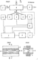
- 1 shows the sample space 9 with gas connections, the electrodes and the observation windows. 1 designates a device for supplying oxygen to the sample space 9 for improved afterburning of particles.
- the pump 2 serves to suck the exhaust gas through the sample space 9.
- the spark gap (not shown) in the sample space 9 is fed by its own high-voltage supply 3 and computer-controlled and triggered by a microprocessor computer unit 7.
- the radiation transmission from the sample space to the registration units 4, 5 and 11 is carried out, for example, by means of multi-fiber light guides or light guide rods A in order to avoid electrical interference due to the RF radiation of the sparks.
- the time registration interval for measuring the line intensities is controlled by the electronics 10 by means of the registration unit 4 designed, for example, as a fast photodiode.
- the sample chamber wall consists at least partially of a medium which is transparent to at least part of the radiation emitted by the plasma (for example from 180 to 3000 nm), for example glass, 13 are the connections for exhaust gas supply, 14 for oxygen supply, and 15 is the connection for suction of the exhaust gas from the sample room.
- A are the connections for fiber light guides or light guide rods, 16a, 16b, .16c, 16d are the electrodes, which consist of the most heat-resistant and inert material possible, for example tungsten or platinum; 16b, 16c and 16d form stable channels due to their pointed electrode ends.
- 6 and 7 show sample chamber electrode arrangements in which the sample chamber window is automatically cleaned by the spark-generated plasma as a result of its high temperature and the resulting shock wave, or contamination can be avoided from the outset.
- the electrodes 18 are arranged so that the spark strikes along the surface of the sample chamber window, whereby the action of the plasma is optimal and also a higher radiation yield is made possible because the emission zone is directly adjacent to the exit surface.
- the cuvette according to FIG. 6 forming the sample chamber 9 is arranged in a cross shape, with electrodes 18 melted or glued in at the side. In the cuvette according to FIG. 7 forming the sample chamber 9, the electrodes 18 are melted into a glass tube on the longitudinal side.
- FIG. 8 and FIG. 9, which shows a section along the line IX-IX in FIG. 8, show a schematic sample space electrode arrangement which corresponds in principle to the designs in so-called TEA lasers.
- 20 are the flat electrode cutting edges, which are embedded in insulating material 21 of the sample space 9.
- the exhaust gas to be detected is sucked through or blown through, for example, perpendicular to the longitudinal direction of the electrodes 20 along the arrows 13, 15.
- the emission is observed along the direction of the electrode cutting edges.
- A is a possible connection for an optical fiber.
Landscapes
- Health & Medical Sciences (AREA)
- Nuclear Medicine, Radiotherapy & Molecular Imaging (AREA)
- Physics & Mathematics (AREA)
- Life Sciences & Earth Sciences (AREA)
- Chemical & Material Sciences (AREA)
- Analytical Chemistry (AREA)
- Biochemistry (AREA)
- General Health & Medical Sciences (AREA)
- General Physics & Mathematics (AREA)
- Immunology (AREA)
- Pathology (AREA)
- Investigating, Analyzing Materials By Fluorescence Or Luminescence (AREA)
Priority Applications (2)
| Application Number | Priority Date | Filing Date | Title |
|---|---|---|---|
| EP19850890047 EP0192919B1 (fr) | 1985-02-25 | 1985-02-25 | Méthode et dispositif de détermination quantitative des constituants de gaz d'échappement combustibles |
| DE8585890047T DE3583137D1 (de) | 1985-02-25 | 1985-02-25 | Verfahren zur quantitativen bestimmung von bestandteilen von verbrennungsabgasen sowie einrichtung zur durchfuehrung des verfahrens. |
Applications Claiming Priority (1)
| Application Number | Priority Date | Filing Date | Title |
|---|---|---|---|
| EP19850890047 EP0192919B1 (fr) | 1985-02-25 | 1985-02-25 | Méthode et dispositif de détermination quantitative des constituants de gaz d'échappement combustibles |
Publications (2)
| Publication Number | Publication Date |
|---|---|
| EP0192919A1 true EP0192919A1 (fr) | 1986-09-03 |
| EP0192919B1 EP0192919B1 (fr) | 1991-06-05 |
Family
ID=8194746
Family Applications (1)
| Application Number | Title | Priority Date | Filing Date |
|---|---|---|---|
| EP19850890047 Expired - Lifetime EP0192919B1 (fr) | 1985-02-25 | 1985-02-25 | Méthode et dispositif de détermination quantitative des constituants de gaz d'échappement combustibles |
Country Status (2)
| Country | Link |
|---|---|
| EP (1) | EP0192919B1 (fr) |
| DE (1) | DE3583137D1 (fr) |
Cited By (5)
| Publication number | Priority date | Publication date | Assignee | Title |
|---|---|---|---|---|
| EP0337933A1 (fr) * | 1988-03-31 | 1989-10-18 | Linde Aktiengesellschaft | Dispositif pour déterminer la contamination d'un gaz et application de ce dispositif |
| WO1993010438A1 (fr) * | 1991-11-15 | 1993-05-27 | Hughes Aircraft Company | Detecteur a fluorescence excite par etincelle |
| DE19502069A1 (de) * | 1995-01-16 | 1996-07-18 | Ver Energiewerke Ag | Anordnung für die Bestimmung von Alkalien in einem Heißgasstrom |
| WO2005068981A3 (fr) * | 2003-12-31 | 2005-10-06 | Honeywell Int Inc | Systeme de capteur a micro-plasma |
| WO2012152621A1 (fr) * | 2011-05-06 | 2012-11-15 | Heinrich-Heine-Universität Düsseldorf | Procédé et système pour la détection d'un premier gaz dans un mélange gazeux comprenant au moins un autre gaz |
Families Citing this family (3)
| Publication number | Priority date | Publication date | Assignee | Title |
|---|---|---|---|---|
| US20100239436A1 (en) | 2005-05-17 | 2010-09-23 | Honeywell International Inc. | A thermal pump |
| CN110146487B (zh) * | 2019-06-11 | 2022-01-04 | 中国热带农业科学院分析测试中心 | 一种原位测定食品中总so2的方法 |
| DE102022133333A1 (de) * | 2022-12-14 | 2024-06-20 | Ruhr-Universität Bochum, Körperschaft des öffentlichen Rechts | Vorrichtung und Verfahren zum Erfassen einer Intensität einer Emission eines Plasmas |
Citations (2)
| Publication number | Priority date | Publication date | Assignee | Title |
|---|---|---|---|---|
| DE1087832B (de) * | 1958-02-10 | 1960-08-25 | Union Carbide Corp | Gasanalysengeraete zum emissionsspektrometrischen Nachweis des Anteils eines Komponent-gases in einem Gasgemisch |
| DE1900309A1 (de) * | 1968-01-03 | 1969-09-04 | Iit Res Inst | Verfahren und Vorrichtung zur Analysierung von Gasen |
-
1985
- 1985-02-25 DE DE8585890047T patent/DE3583137D1/de not_active Expired - Lifetime
- 1985-02-25 EP EP19850890047 patent/EP0192919B1/fr not_active Expired - Lifetime
Patent Citations (2)
| Publication number | Priority date | Publication date | Assignee | Title |
|---|---|---|---|---|
| DE1087832B (de) * | 1958-02-10 | 1960-08-25 | Union Carbide Corp | Gasanalysengeraete zum emissionsspektrometrischen Nachweis des Anteils eines Komponent-gases in einem Gasgemisch |
| DE1900309A1 (de) * | 1968-01-03 | 1969-09-04 | Iit Res Inst | Verfahren und Vorrichtung zur Analysierung von Gasen |
Non-Patent Citations (5)
| Title |
|---|
| APPLIED SPECTROSCOPY, Band 15, Nr. 4, 1961, Seiten 99-101; R.S. HULLINGS: "Minimizing matrix effects in stainless steel, type 422, using oxygen in the analytical gap" * |
| APPLIED SPECTROSCOPY, Band 29, Nr 5, 09. Oktober 1975, Seiten 436-438; R.S. VOGEL: "A Semiautomated device for controlled atmospheres in optical emission spectroscopy" * |
| APPLIED SPECTROSCOPY, Band 35, Nr. 2, März-April 1982, Seiten 92-99, Baltimore, Maryland, US; R.E. RUSSO et al.: Determination of atomic and molecular excited-state lifetimes using an optoelectronic cross-correlation method" * |
| APPLIED SPECTROSCOPY, Band 37, Nr. 6, November-Dezember 1983, Seiten 537-539, Society for Applied Spectroscopy, Baltimore Maryland, US; S. G. BARNHART et al.: Fiber optic signal transmission to reduce radio-frequency interference from high-voltage spark source" * |
| JOURNAL OF PHYSICS E, SCIENT. INSTR., Band 12, Nr. 5, Mai 1979, Seiten 397-402, The Institute of Physics, GB; D.R. AIREY: "A rapid-scanning polychromator for time-resolved temperature and radius measurements in 40kA SF6 arcs" * |
Cited By (9)
| Publication number | Priority date | Publication date | Assignee | Title |
|---|---|---|---|---|
| EP0337933A1 (fr) * | 1988-03-31 | 1989-10-18 | Linde Aktiengesellschaft | Dispositif pour déterminer la contamination d'un gaz et application de ce dispositif |
| CH675773A5 (fr) * | 1988-03-31 | 1990-10-31 | Sulzer Ag | |
| US5168323A (en) * | 1988-03-31 | 1992-12-01 | Sulzer Brothers Limited | Device and method for determining impurities in a gas |
| WO1993010438A1 (fr) * | 1991-11-15 | 1993-05-27 | Hughes Aircraft Company | Detecteur a fluorescence excite par etincelle |
| US5333487A (en) * | 1991-11-15 | 1994-08-02 | Hughes Aircraft Company | Spark-excited fluorescence sensor |
| DE19502069A1 (de) * | 1995-01-16 | 1996-07-18 | Ver Energiewerke Ag | Anordnung für die Bestimmung von Alkalien in einem Heißgasstrom |
| DE19502069C2 (de) * | 1995-01-16 | 1999-04-29 | Ver Energiewerke Ag | Anordnung für die optische Bestimmung der Konzentration von Alkalien in einem Heißgasstrom |
| WO2005068981A3 (fr) * | 2003-12-31 | 2005-10-06 | Honeywell Int Inc | Systeme de capteur a micro-plasma |
| WO2012152621A1 (fr) * | 2011-05-06 | 2012-11-15 | Heinrich-Heine-Universität Düsseldorf | Procédé et système pour la détection d'un premier gaz dans un mélange gazeux comprenant au moins un autre gaz |
Also Published As
| Publication number | Publication date |
|---|---|
| DE3583137D1 (de) | 1991-07-11 |
| EP0192919B1 (fr) | 1991-06-05 |
Similar Documents
| Publication | Publication Date | Title |
|---|---|---|
| DE69115803T2 (de) | Gepulstes Flammanalyseverfahren und Detektorvorrichtung zum Gebrauch dafür | |
| EP2382460B1 (fr) | Procédé et dispositif de détection de gaz ionisables | |
| DE69424301T2 (de) | Kontinuierlicher mikrowellenplasma-elementsensor in echtzeit | |
| Archontaki et al. | Evaluation of an isolated droplet sample introduction system for laser-induced breakdown spectroscopy | |
| DE3119903A1 (de) | Fluoreszenzspektrometer | |
| DE2416997A1 (de) | Gasanalysator | |
| EP0238871A2 (fr) | Dispositif de mesure pour l'analyse des gaz d'échappement de moteurs à combustion et procédé pour l'utilisation d'un tel dispositif | |
| DE2407133A1 (de) | Verfahren und vorrichtung zur bestimmung von stickoxid | |
| DE69226778T2 (de) | Vorrichtung und verfahren zum gasnachweis | |
| EP0257248A2 (fr) | Appareil de mesure de la diffusion de lumière | |
| CH702387B1 (de) | Brennersystem mit einem Verunreinigungsdetektionssystem. | |
| DE19512793A1 (de) | Analysesystem und -verfahren | |
| DE3044959A1 (de) | Flammenfotometer-nachweisanalysator | |
| EP0192919B1 (fr) | Méthode et dispositif de détermination quantitative des constituants de gaz d'échappement combustibles | |
| EP3553499A1 (fr) | Analyseur de gaz et procédé de mesure des oxydes d'azote dans un gaz d'échappement | |
| DE69530189T2 (de) | Verbessertes gepulstes Entladungssystem | |
| DE102005018926B4 (de) | Verfahren und Plasmadüse zum Erzeugen eines mittels hochfrequenter Hochspannung erzeugten atmosphärischen Plasmastrahls umfassend eine Vorrichtung jeweils zur Charakterisierung einer Oberfläche eines Werkstückes | |
| DE60036801T2 (de) | Vorrichtung zur kontinuierlichen überwachung von emissionen verschiedener metalle in rauhen umgebungen | |
| DE3840106C2 (de) | Meßfühler für ein tragbares Analysegerät zur Analyse der optischen Emission eines durch elektrische Entladung an einer festen leitfähigen Probe erzeugten Plasmas | |
| DE102009057130A1 (de) | Verfahren zur Analyse der Zusammensetzung von Gasgemischen | |
| DE2322293A1 (de) | Vorrichtung und verfahren zur analyse von organischem kohlenstoff in waessrigen systemen | |
| DE19957808C2 (de) | Verfahren zur Bestimmung von Stoffkonzentrationen und/oder der Strömungsgeschwindigkeit in einem Gas, Aerosol oder Staub und Vorrichtungen zur Durchführung des Verfahrens | |
| AT384490B (de) | Verfahren zur quantitativen bestimmung von bestandteilen von verbrennungsabgasen sowie einrichtung zur ausuebung des verfahrens | |
| DE2144642A1 (de) | Verfahren und Vorrichtung zum Überführen einer Probe in Atome zwecks Analyse der Probe durch Atomspektroskopie | |
| DE69929955T2 (de) | Spektrophotometrie und flammenionisationsdetektion kombinierende vorrichtung zur untersuchung eines gasförmigen gemisches |
Legal Events
| Date | Code | Title | Description |
|---|---|---|---|
| PUAI | Public reference made under article 153(3) epc to a published international application that has entered the european phase |
Free format text: ORIGINAL CODE: 0009012 |
|
| AK | Designated contracting states |
Kind code of ref document: A1 Designated state(s): DE FR GB IT |
|
| ITCL | It: translation for ep claims filed |
Representative=s name: MODIANO & ASSOCIATI S.R.L. |
|
| EL | Fr: translation of claims filed | ||
| 17P | Request for examination filed |
Effective date: 19870217 |
|
| 17Q | First examination report despatched |
Effective date: 19880715 |
|
| GRAA | (expected) grant |
Free format text: ORIGINAL CODE: 0009210 |
|
| AK | Designated contracting states |
Kind code of ref document: B1 Designated state(s): DE FR GB IT |
|
| GBT | Gb: translation of ep patent filed (gb section 77(6)(a)/1977) | ||
| REF | Corresponds to: |
Ref document number: 3583137 Country of ref document: DE Date of ref document: 19910711 |
|
| ET | Fr: translation filed | ||
| ITF | It: translation for a ep patent filed | ||
| PGFP | Annual fee paid to national office [announced via postgrant information from national office to epo] |
Ref country code: DE Payment date: 19920203 Year of fee payment: 8 |
|
| PGFP | Annual fee paid to national office [announced via postgrant information from national office to epo] |
Ref country code: GB Payment date: 19920211 Year of fee payment: 8 |
|
| PGFP | Annual fee paid to national office [announced via postgrant information from national office to epo] |
Ref country code: FR Payment date: 19920227 Year of fee payment: 8 |
|
| PLBE | No opposition filed within time limit |
Free format text: ORIGINAL CODE: 0009261 |
|
| STAA | Information on the status of an ep patent application or granted ep patent |
Free format text: STATUS: NO OPPOSITION FILED WITHIN TIME LIMIT |
|
| 26N | No opposition filed | ||
| PG25 | Lapsed in a contracting state [announced via postgrant information from national office to epo] |
Ref country code: GB Effective date: 19930225 |
|
| GBPC | Gb: european patent ceased through non-payment of renewal fee |
Effective date: 19930225 |
|
| PG25 | Lapsed in a contracting state [announced via postgrant information from national office to epo] |
Ref country code: FR Effective date: 19931029 |
|
| PG25 | Lapsed in a contracting state [announced via postgrant information from national office to epo] |
Ref country code: DE Effective date: 19931103 |
|
| REG | Reference to a national code |
Ref country code: FR Ref legal event code: ST |