EP0192933A2 - Procédé et dispositif de traitement thermique notamment de pièces métalliques - Google Patents
Procédé et dispositif de traitement thermique notamment de pièces métalliques Download PDFInfo
- Publication number
- EP0192933A2 EP0192933A2 EP86100308A EP86100308A EP0192933A2 EP 0192933 A2 EP0192933 A2 EP 0192933A2 EP 86100308 A EP86100308 A EP 86100308A EP 86100308 A EP86100308 A EP 86100308A EP 0192933 A2 EP0192933 A2 EP 0192933A2
- Authority
- EP
- European Patent Office
- Prior art keywords
- furnace chamber
- batches
- furnace
- batch
- chamber
- Prior art date
- Legal status (The legal status is an assumption and is not a legal conclusion. Google has not performed a legal analysis and makes no representation as to the accuracy of the status listed.)
- Withdrawn
Links
Images



Classifications
-
- F—MECHANICAL ENGINEERING; LIGHTING; HEATING; WEAPONS; BLASTING
- F27—FURNACES; KILNS; OVENS; RETORTS
- F27B—FURNACES, KILNS, OVENS OR RETORTS IN GENERAL; OPEN SINTERING OR LIKE APPARATUS
- F27B9/00—Furnaces through which the charge is moved mechanically, e.g. of tunnel type; Similar furnaces in which the charge moves by gravity
- F27B9/02—Furnaces through which the charge is moved mechanically, e.g. of tunnel type; Similar furnaces in which the charge moves by gravity of multiple-track type; of multiple-chamber type; Combinations of furnaces
- F27B9/028—Multi-chamber type furnaces
-
- C—CHEMISTRY; METALLURGY
- C21—METALLURGY OF IRON
- C21D—MODIFYING THE PHYSICAL STRUCTURE OF FERROUS METALS; GENERAL DEVICES FOR HEAT TREATMENT OF FERROUS OR NON-FERROUS METALS OR ALLOYS; MAKING METAL MALLEABLE, e.g. BY DECARBURISATION OR TEMPERING
- C21D1/00—General methods or devices for heat treatment, e.g. annealing, hardening, quenching or tempering
- C21D1/74—Methods of treatment in inert gas, controlled atmosphere, vacuum or pulverulent material
-
- C—CHEMISTRY; METALLURGY
- C21—METALLURGY OF IRON
- C21D—MODIFYING THE PHYSICAL STRUCTURE OF FERROUS METALS; GENERAL DEVICES FOR HEAT TREATMENT OF FERROUS OR NON-FERROUS METALS OR ALLOYS; MAKING METAL MALLEABLE, e.g. BY DECARBURISATION OR TEMPERING
- C21D9/00—Heat treatment, e.g. annealing, hardening, quenching or tempering, adapted for particular articles; Furnaces therefor
-
- F—MECHANICAL ENGINEERING; LIGHTING; HEATING; WEAPONS; BLASTING
- F27—FURNACES; KILNS; OVENS; RETORTS
- F27B—FURNACES, KILNS, OVENS OR RETORTS IN GENERAL; OPEN SINTERING OR LIKE APPARATUS
- F27B9/00—Furnaces through which the charge is moved mechanically, e.g. of tunnel type; Similar furnaces in which the charge moves by gravity
- F27B9/04—Furnaces through which the charge is moved mechanically, e.g. of tunnel type; Similar furnaces in which the charge moves by gravity adapted for treating the charge in vacuum or special atmosphere
- F27B9/045—Furnaces with controlled atmosphere
-
- F—MECHANICAL ENGINEERING; LIGHTING; HEATING; WEAPONS; BLASTING
- F27—FURNACES; KILNS; OVENS; RETORTS
- F27B—FURNACES, KILNS, OVENS OR RETORTS IN GENERAL; OPEN SINTERING OR LIKE APPARATUS
- F27B9/00—Furnaces through which the charge is moved mechanically, e.g. of tunnel type; Similar furnaces in which the charge moves by gravity
- F27B9/14—Furnaces through which the charge is moved mechanically, e.g. of tunnel type; Similar furnaces in which the charge moves by gravity characterised by the path of the charge during treatment; characterised by the means by which the charge is moved during treatment
-
- F—MECHANICAL ENGINEERING; LIGHTING; HEATING; WEAPONS; BLASTING
- F27—FURNACES; KILNS; OVENS; RETORTS
- F27B—FURNACES, KILNS, OVENS OR RETORTS IN GENERAL; OPEN SINTERING OR LIKE APPARATUS
- F27B9/00—Furnaces through which the charge is moved mechanically, e.g. of tunnel type; Similar furnaces in which the charge moves by gravity
- F27B9/30—Details, accessories or equipment specially adapted for furnaces of these types
- F27B9/40—Arrangements of controlling or monitoring devices
-
- F—MECHANICAL ENGINEERING; LIGHTING; HEATING; WEAPONS; BLASTING
- F27—FURNACES; KILNS; OVENS; RETORTS
- F27B—FURNACES, KILNS, OVENS OR RETORTS IN GENERAL; OPEN SINTERING OR LIKE APPARATUS
- F27B19/00—Combinations of different kinds of furnaces that are not all covered by any single one of main groups F27B1/00 - F27B17/00
- F27B19/04—Combinations of different kinds of furnaces that are not all covered by any single one of main groups F27B1/00 - F27B17/00 arranged for associated working
-
- F—MECHANICAL ENGINEERING; LIGHTING; HEATING; WEAPONS; BLASTING
- F27—FURNACES; KILNS; OVENS; RETORTS
- F27B—FURNACES, KILNS, OVENS OR RETORTS IN GENERAL; OPEN SINTERING OR LIKE APPARATUS
- F27B9/00—Furnaces through which the charge is moved mechanically, e.g. of tunnel type; Similar furnaces in which the charge moves by gravity
- F27B9/14—Furnaces through which the charge is moved mechanically, e.g. of tunnel type; Similar furnaces in which the charge moves by gravity characterised by the path of the charge during treatment; characterised by the means by which the charge is moved during treatment
- F27B9/16—Furnaces through which the charge is moved mechanically, e.g. of tunnel type; Similar furnaces in which the charge moves by gravity characterised by the path of the charge during treatment; characterised by the means by which the charge is moved during treatment the charge moving in a circular or arcuate path
-
- F—MECHANICAL ENGINEERING; LIGHTING; HEATING; WEAPONS; BLASTING
- F27—FURNACES; KILNS; OVENS; RETORTS
- F27D—DETAILS OR ACCESSORIES OF FURNACES, KILNS, OVENS OR RETORTS, IN SO FAR AS THEY ARE OF KINDS OCCURRING IN MORE THAN ONE KIND OF FURNACE
- F27D19/00—Arrangements of controlling devices
- F27D2019/0028—Regulation
- F27D2019/0059—Regulation involving the control of the conveyor movement, e.g. speed or sequences
- F27D2019/0062—Regulation involving the control of the conveyor movement, e.g. speed or sequences control of the workpiece stay in different zones
-
- F—MECHANICAL ENGINEERING; LIGHTING; HEATING; WEAPONS; BLASTING
- F27—FURNACES; KILNS; OVENS; RETORTS
- F27D—DETAILS OR ACCESSORIES OF FURNACES, KILNS, OVENS OR RETORTS, IN SO FAR AS THEY ARE OF KINDS OCCURRING IN MORE THAN ONE KIND OF FURNACE
- F27D19/00—Arrangements of controlling devices
- F27D2019/0028—Regulation
- F27D2019/0068—Regulation involving a measured inflow of a particular gas in the enclosure
-
- F—MECHANICAL ENGINEERING; LIGHTING; HEATING; WEAPONS; BLASTING
- F27—FURNACES; KILNS; OVENS; RETORTS
- F27M—INDEXING SCHEME RELATING TO ASPECTS OF THE CHARGES OR FURNACES, KILNS, OVENS OR RETORTS
- F27M2001/00—Composition, conformation or state of the charge
- F27M2001/15—Composition, conformation or state of the charge characterised by the form of the articles
- F27M2001/1539—Metallic articles
Definitions
- the invention relates to a method for the heat treatment of in particular metallic workpieces with the features of the preamble of the main claim. Furthermore, the invention relates to a device for performing the method, as characterized by the features of the preamble of claim 5.
- the object of the invention is to create a method for the continuous heat treatment of, in particular, metallic workpieces in a furnace chamber containing a corresponding atmosphere, which does not require a complete emptying of the furnace chamber beforehand when changing from one batch to another allowed to treat batches of different types at the same time.
- the new process has the advantage of taking into account the actual state of the workpieces per batch and accordingly allowing the batch to be individually exposed to the furnace atmosphere.
- the dwell time had to be determined in the worst-case scenario to be expected, which then resulted, for example in the case of other batches, in an excessive heat treatment.
- each batch is preheated to the respective process temperature in the furnace chamber in a preheating zone before it is introduced into the furnace chamber. There is therefore no need to fear that batches already in the furnace chamber are in the process process can be influenced by a nearby cold batch.
- the calculation of the residence time is simplified, for example, if the state variables and the composition of the furnace atmosphere over the treatment time of a particular batch be kept constant.
- a special, flexible process that also meets the most varied of workpiece shapes results if the necessary dwell time is calculated for each batch while it is in the furnace chamber from the state variables, including the composition of the furnace atmosphere and the workpiece shape and type.
- state variables including the composition of the furnace atmosphere and the workpiece shape and type.
- it is not essential to keep the chemical and physical parameters of the furnace atmosphere constant within narrow limits.
- this measure makes it easy to take into account the actual status of the individual batches.
- the transport device is assigned a control device having a memory, particularly good utilization of the transport device is possible because immediately after the unloading of a batch, the space freed up can be taken up by a new batch. In addition, this method allows automatic, automatic operation that does not require manual intervention.
- a good use of space within the furnace chamber is obtained if the transport device within the furnace chamber has a closed path along which the batches can be moved. This also results in the possibility of moving the batches along the path in such a way that only the shortest distance has to be covered for removal or reloading, because the batches or the empty spaces are from both sides of the loading or removal opening can approach.
- the removal opening and the loading opening can be immediately adjacent or they can be diametrically opposed with respect to the path and the center of the furnace chamber.
- a particularly simple transport device is obtained if, in order to form the closed path in the furnace chamber, there is a cooker which is rotatably mounted about the vertical and which is selectively moved in one or the other direction by a drive device controlled by the control device, or at least in at least one direction is rotatable, with the stove the position transmitter is coupled with means that the control device determines the respective position of the batches or the position of vacancies on the stove.
- the transport device contains pushers or pullers, which transport the batches through the removal or loading opening to or from the cooker.
- the control device can also be combined with a computer which, for each batch located in the furnace chamber, during its presence, from the state variables and the composition of the furnace atmosphere, i.e. their dwell time is determined from their physical and chemical parameters as well as the shape and type of workpiece within the respective batch.
- FIG. 1 shows a furnace system 1 which contains a preheating zone 2 and an industrial furnace 3 connected to the outlet of the preheating zone 2 for heat treatment, in particular metallic workpieces, in which the workpieces are carburized, for example, in an appropriate atmosphere.
- the drives and devices of the preheating zone 2 and the furnace 3 are controlled by means of a computer 4, which is connected to the respective drive means via schematically indicated control lines 5 and 6.
- the computer 4 receives its data and its program via a memory 8 connected via a line 7 and via appropriate sensors.
- the preheating zone 2 has a rectangular preheating chamber 9 lined with heat-insulating material, on one end of which there is a loading opening 11, while on the end of a side wall remote from the loading opening 11 a removal opening 12 is provided. Between the loading opening 11 and the removal opening 12, a grate or stove extends in the preheating chamber 9, on which the batches 13 located in baskets or on pallets gradually move from the loading opening 11 to the removal opening 12. Upstream of the feed opening 11 is a lock 14, which can be optionally locked by means of two doors 15 and 16 on the one hand to the feed opening 11 of the preheating chamber 9 or through the lock door 16 to the outside atmosphere.
- the two lock doors 15 and 16 are assigned electrical or hydraulic drive means, not shown, for opening and closing.
- a hydraulically actuated transverse pusher 17 On a side wall of the lock 14 opposite the loading opening 11 there is provided, for example, a hydraulically actuated transverse pusher 17, with which a batch 18 brought into the chamber of the lock 14 can be pushed through the loading opening 11 onto the hearth of the actual preheating chamber 9 when the lock door 15 is open , at the same time all batches 13 located on this hearth advance by the corresponding amount in the direction of the removal opening 12.
- a further, for example hydraulically actuatable, cross pusher 19 is provided at a location opposite the removal opening 12 in this side wall, which, when activated, shuts down the corresponding batch 13 in front of it from the stove in the preheating chamber 9 transported through the removal opening 12.
- the furnace 3 contains a furnace chamber 21 also lined with heat-insulating material, the interior of which is accessible via a loading opening 22 and a removal opening 23.
- the loading opening 22 of the furnace 3 is connected to the removal opening 12 of the preheating chamber 9, a door 24, which can also be actuated by corresponding drive means, not shown, being arranged between the two openings, through which the interior of the preheating chamber 9 can optionally be shut off from the interior of the furnace chamber 21.
- the door 24 is opened only for transferring the batches 13 from the preheating chamber 9 into the furnace chamber 21.
- the removal opening 23 optionally connects to further treatment devices for the workpieces, which is why the channel leading away from the removal opening 23 is shown broken off.
- the removal opening 23 can also be optionally blocked by a corresponding door 25.
- the space delimited by the lining 28 has a circular plan with an arched ceiling 31.
- a likewise circular rotary hearth 32 projects into the cylindrical space delimited by the brick lining 28 and has a heat-insulating support 33 on its upper side.
- the rotary hearth 32 is rotatably mounted in the base 27 by means of a corresponding vertical bearing 34 about the vertical axis, which runs concentrically to the space delimited by the lining 28.
- a cylindrical circumferential sword 35 is arranged on the underside thereof, which dips into an annular channel 36 filled with oil and open at the top, which is provided on the underside of the rotating hearth 32 and radially laterally over the latter, such as shown, survives.
- Rotary hearth 32 and hood 29 together limit furnace chamber 21.
- a geared motor 37 is fastened in the base 27, the output gear 38 of which meshes with a gear 39 which is non-rotatably connected to the rotary hearth 32 and which is coaxial with the axis of rotation of the rotary hearth 32.
- Geared to the gear 39 is also a rotary angle sensor 41, the electrical output of which is connected to the computer 4 via a connecting line 42, so that it can determine the respective azimuth angle of the rotary hearth 32 via the rotary angle sensor 41.
- end tubes 43 are inserted into the hood 29, in which burners are inserted for heating the furnace atmosphere.
- known devices are provided and electrically connected to the computer 4, which are therefore also not shown in detail.
- the furnace system 1 described so far operates as follows: as soon as a parking space on the rotary hearth 32 has become free as a result of the removal of one of the batches 13, the computer 4 sets the gear motor 37 in motion until the angular position of the rotary hearth reported by the angle transmitter 41 32 for the computer 4 reveals that this vacant parking space is located opposite the loading opening 22. As soon as this position is reached, the geared motor 37 is stopped and the drive for the door 24 is switched on by the computer 4 and the door 24 is opened.
- the batch 13a adjacent to the cross pusher 19 becomes by the cross pusher 19, after the drive has also been switched on by the computer 4, pushed down from the stove in the preheating zone 9 and through the removal opening 12 and the loading opening 22 until the batch 13a has the free space on the rotary hearth 32 has taken.
- the computer 4 After retraction of the cross pusher 19 in the starting position shown in FIG. 1, the computer 4 causes the door 24 to be closed and instead the lock door 15 to be opened, so that the cross pusher 17 after the computer 4 has started its drive which is in the chamber of the lock 14 waiting batch 13b can advance to the stove in the preheating chamber 9. Simultaneously with this, the cross pusher 17 moves all the batches 13 waiting in the preheating chamber 9 one position further until the arrangement shown in FIG. 1 is reached again, in which a batch 13a is positioned in front of the removal opening 12.
- the cross pusher 17 is then withdrawn and the computer 4 causes the lock door 15 to be closed.
- a new batch 13b can now be entered into the free lock 14 after the lock door 16 has been opened.
- the computer 4 From the batch 13a newly transferred to the rotary hearth 32, the computer 4 stores in its working memory 8 the time of transfer to the oven 3 and the angular position of this batch 13a on the rotary hearth 32.
- the computer 4 can calculate the necessary dwell time for each batch on the basis of this data and the physical and chemical parameters of the furnace atmosphere in the furnace 3 determined by him with corresponding known sensors. Since the batches 13 located in the preheating chamber 9 are already heated to the process temperature - the preheating chamber 9 is heated by corresponding heating elements (not illustrated) - the batches 13 which have just been transferred into the furnace chamber also do not influence the process temperature for the immediately adjacent ones, which have been used for a long time Oven 3 batches 13.
- the computer 4 determines, based on the data contained in the memory 8, that the dwell time has expired for one of the batches 13c to 13i located in the furnace 3, it starts the geared motor 37 again in order to rotate the rotary hearth 32 until the respective batch, the residence time of which has expired in the furnace, is on the rotary hearth 32 in front of the removal opening 23.
- the computer 4 has determined that this setting has been reached by means of the rotary angle sensor 41, the geared motor 37 is switched off and the rotary hearth 32 therefore stops.
- the door 25 After the door 25 has been opened, the corresponding batch 13 can be pulled down from the rotary hearth 32 through the removal opening 23 by means of the broken puller 44, in order to be made available for a further processing step. Then the door 25 is closed again; Of course, the door 25 can be a further lock door of a lock, not shown, connected to the removal opening 23 helps prevent a greater loss of furnace atmosphere.
- the now vacant parking space on the rotary hearth 32 can be taken up by a batch 13a advancing from the preheating chamber 9 in the manner described above, for which purpose the computer 4 correspondingly starts the gear motor 37 until the parking space on the rotary hearth 32 in front of the loading opening 22 is located.
- the rotary hearth 32 forms a transport device for the batches 13c to 13i, which can be moved by means of the rotary hearth 32 along a closed path in the chamber of the oven 3.
- control of the rotary hearth 32 provided by the computer 4 can also mean that the rotary hearth 32 rotates continuously during the heat treatment process due to the switched-on gear motor 37 and is only stopped by the computer 4 in the corresponding correct position during the actual loading and unloading process and after that it is constantly started again.
- control system can be designed such that depending on the position of the batch 13c to 13i to be unloaded from the rotary hearth 32, relative to the removal opening 23, it sets the rotary hearth 32 either to the left or to the right, so that in each case only the shortest path has to be covered .
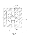
- the loading openings 22 and 23 can diametrically oppose each other with respect to the path given by the rotary hearth 32 or the center of the chamber of the furnace 3 overlap.
- Arrows 45 and 46 indicate the direction of movement of the batches during loading and unloading.
- a double arrow 47 illustrates the optional traveling direction of the batches 13 within the chamber of the furnace 3.
- This arrangement has the advantage that the rotary hearth 32 practically does not have to be moved or only moves a little between the emptying and reloading, since the parking space freed up by the removal is in this way either directly in front of or in the immediate vicinity of the loading opening .
Landscapes
- Engineering & Computer Science (AREA)
- Chemical & Material Sciences (AREA)
- Mechanical Engineering (AREA)
- General Engineering & Computer Science (AREA)
- Metallurgy (AREA)
- Thermal Sciences (AREA)
- Crystallography & Structural Chemistry (AREA)
- Materials Engineering (AREA)
- Physics & Mathematics (AREA)
- Organic Chemistry (AREA)
- Heat Treatments In General, Especially Conveying And Cooling (AREA)
- Tunnel Furnaces (AREA)
- Control Of Heat Treatment Processes (AREA)
- Heat Treatment Of Articles (AREA)
- Furnace Charging Or Discharging (AREA)
- Furnace Details (AREA)
Applications Claiming Priority (2)
| Application Number | Priority Date | Filing Date | Title |
|---|---|---|---|
| DE3506131A DE3506131C1 (de) | 1985-02-22 | 1985-02-22 | Verfahren zum Waermebehandeln von insbesondere metallischen Werkstuecken und Vorrichtung zur Durchfuehrung des Verfahrens |
| DE3506131 | 1985-02-22 |
Publications (2)
| Publication Number | Publication Date |
|---|---|
| EP0192933A2 true EP0192933A2 (fr) | 1986-09-03 |
| EP0192933A3 EP0192933A3 (fr) | 1988-08-31 |
Family
ID=6263222
Family Applications (1)
| Application Number | Title | Priority Date | Filing Date |
|---|---|---|---|
| EP86100308A Withdrawn EP0192933A3 (fr) | 1985-02-22 | 1986-01-11 | Procédé et dispositif de traitement thermique notamment de pièces métalliques |
Country Status (6)
| Country | Link |
|---|---|
| EP (1) | EP0192933A3 (fr) |
| JP (1) | JPS61231121A (fr) |
| DE (1) | DE3506131C1 (fr) |
| DK (1) | DK34286A (fr) |
| NO (1) | NO860197L (fr) |
| PL (1) | PL258076A1 (fr) |
Cited By (1)
| Publication number | Priority date | Publication date | Assignee | Title |
|---|---|---|---|---|
| CN112964067A (zh) * | 2021-02-23 | 2021-06-15 | 内蒙古工业大学 | 一种冶金炉加料设备 |
Families Citing this family (9)
| Publication number | Priority date | Publication date | Assignee | Title |
|---|---|---|---|---|
| DE3640325C1 (de) * | 1986-11-26 | 1988-02-04 | Ipsen Ind Internat Gmbh | Vorrichtung zur Waermebehandlung metallischer Werkstuecke in einer Kohlungsatmosphaere |
| US4763880A (en) * | 1987-04-03 | 1988-08-16 | Holcroft/Loftus Inc. | Rotary hearth multi-chamber, multi-purpose furnace system |
| US5187670A (en) * | 1990-11-05 | 1993-02-16 | Caterpillar Inc. | Control system for scheduling parts in a heat-treating process |
| DE4431608C5 (de) * | 1994-09-06 | 2004-02-05 | Aichelin Gmbh | Verfahren und Vorrichtung zum Wärmebehandeln metallischer Werkstücke |
| RU2151215C1 (ru) * | 1998-06-15 | 2000-06-20 | Краснов Виктор Дмитриевич | Агрегат химико-термической обработки с нагревателем в слое катализатора |
| DE19928990C2 (de) * | 1999-06-24 | 2002-04-11 | Siemens Ag | Drehofen |
| RU2236471C1 (ru) * | 2003-01-14 | 2004-09-20 | Погорелко Михаил Павлович | Безретортный эндогенератор конструкции погорелко |
| DE102012019653A1 (de) | 2012-10-08 | 2014-04-10 | Ipsen International Gmbh | Gasdichter schutzgasbegaster Industrieofen, insbesondere Kammerofen, Durchstoßofen, Drehherdofen oder Ringherdofen |
| AT524549B1 (de) * | 2021-10-15 | 2022-07-15 | Ebner Ind Ofenbau | Industrieofenanlage |
Family Cites Families (6)
| Publication number | Priority date | Publication date | Assignee | Title |
|---|---|---|---|---|
| DE1216910B (de) * | 1960-03-05 | 1966-05-18 | Erich Menzel | Beschickungs- und Entnahmeeinrichtung fuer Drehherdoefen zum Erwaermen von Knueppeln, Spaltstuecken oder aehnlichen Teilen |
| FR1560499A (fr) * | 1967-02-15 | 1969-03-21 | ||
| JPS6010093B2 (ja) * | 1978-01-09 | 1985-03-15 | 住友金属工業株式会社 | 回転炉等連続加熱炉の運転制御方法 |
| US4288062A (en) * | 1979-08-09 | 1981-09-08 | Holcroft | Apparatus for control and monitoring of the carbon potential of an atmosphere in a heat-processing furnace |
| DE3037643A1 (de) * | 1980-10-04 | 1982-05-13 | Linde Ag, 6200 Wiesbaden | Verfahren und vorrichtung zum entkohlenden oder kohlungsneutralen gluehen von metallteilen |
| DE8421677U1 (de) * | 1984-07-20 | 1985-01-03 | Ipsen Industries International Gmbh, 4190 Kleve | Drehherdofen zur waermebehandlung metallischer werkstuecke |
-
1985
- 1985-02-22 DE DE3506131A patent/DE3506131C1/de not_active Expired
-
1986
- 1986-01-11 EP EP86100308A patent/EP0192933A3/fr not_active Withdrawn
- 1986-01-21 NO NO860197A patent/NO860197L/no unknown
- 1986-01-22 JP JP61011821A patent/JPS61231121A/ja active Granted
- 1986-01-22 DK DK34286A patent/DK34286A/da not_active Application Discontinuation
- 1986-02-21 PL PL25807686A patent/PL258076A1/xx unknown
Cited By (1)
| Publication number | Priority date | Publication date | Assignee | Title |
|---|---|---|---|---|
| CN112964067A (zh) * | 2021-02-23 | 2021-06-15 | 内蒙古工业大学 | 一种冶金炉加料设备 |
Also Published As
| Publication number | Publication date |
|---|---|
| EP0192933A3 (fr) | 1988-08-31 |
| JPH0465889B2 (fr) | 1992-10-21 |
| PL258076A1 (en) | 1986-12-16 |
| DE3506131C1 (de) | 1986-05-22 |
| NO860197L (no) | 1986-08-25 |
| DK34286A (da) | 1986-08-23 |
| JPS61231121A (ja) | 1986-10-15 |
| DK34286D0 (da) | 1986-01-22 |
Similar Documents
| Publication | Publication Date | Title |
|---|---|---|
| DE69509613T2 (de) | Bäckereiofen zum kontinuierlichen Kochen von Back- oder Konditorwaren oder ähnlichen | |
| DE3506131C1 (de) | Verfahren zum Waermebehandeln von insbesondere metallischen Werkstuecken und Vorrichtung zur Durchfuehrung des Verfahrens | |
| DE2604667C3 (de) | Drehherdofen | |
| DE3215509C2 (fr) | ||
| EP0621904B1 (fr) | Dispositif de traitement thermique de pieces metalliques | |
| EP0216392B1 (fr) | Procédé et installation pour le traitement de produits divers | |
| EP0236666B1 (fr) | Procédé de réchauffage de produits semi-finis provenant d'installations de coulée continue ou d'installations de formage en vue de leur chargement dans des installations de formage ou de finissage | |
| EP0270043A2 (fr) | Procédé de traitement thermique, en particulier de produits céramiques plutôt plats, et four continu pour sa réalisation | |
| DE3435376C2 (de) | Verfahren zur Wärmebehandlung von Werkstücken | |
| DE4213936A1 (de) | Waermebehandlungssystem | |
| DE3726802A1 (de) | Verfahren zum waermebehandeln von metallischen werkstuecken sowie vorrichtung zur durchfuehrung des verfahrens | |
| DE2846818C2 (de) | Vorrichtung zum Aufheizen von kalten und/oder warmen Stahlblöcken | |
| DE3209245C2 (fr) | ||
| DE1758011B1 (de) | Durchlaufofen zum Aufkohlen oder Karbonitrieren | |
| DE69104377T2 (de) | Steuersystem zur planung der werkstückbehandlung in einem wärmebehandlungsverfahren. | |
| DE618872C (de) | Drehrohrofen | |
| DE3314943A1 (de) | Vorrichtung und verfahren zur beschickung elektrothermischer schmelzoefen | |
| DE722948C (de) | Ofen zum abwechselnden Erwaermen und Abkuehlen des Gluehgutes | |
| DE68906359T2 (de) | Ofen zum Wärmen, Halten und Speichern metallurgischer Produkte. | |
| DE1417551A1 (de) | Verfahren und Anlage zur Herstellung von Backwaren | |
| DE2303734A1 (de) | Hubbalkenofen zum erwaermen von werkstuecken wie brammen, bloecke und dergleichen vor dem walzen | |
| DE70654C (de) | Ofenanlage zum Rösten, Brennen oder Trocknen | |
| DE2321132C3 (de) | Ofen zur Wärmebehandlung | |
| DE60119301T2 (de) | Durchlaufofen zur Herstellung von metallischen Oxyden | |
| DE1928732C3 (de) | Einrichtung zur Steuerung einer Beschickungs- und Entnahmevorrichtung für einen Ofen zum Erwärmen von Brammen |
Legal Events
| Date | Code | Title | Description |
|---|---|---|---|
| PUAI | Public reference made under article 153(3) epc to a published international application that has entered the european phase |
Free format text: ORIGINAL CODE: 0009012 |
|
| AK | Designated contracting states |
Kind code of ref document: A2 Designated state(s): AT DE FR GB IT |
|
| PUAL | Search report despatched |
Free format text: ORIGINAL CODE: 0009013 |
|
| AK | Designated contracting states |
Kind code of ref document: A3 Designated state(s): AT DE FR GB IT |
|
| STAA | Information on the status of an ep patent application or granted ep patent |
Free format text: STATUS: THE APPLICATION IS DEEMED TO BE WITHDRAWN |
|
| 18D | Application deemed to be withdrawn |
Effective date: 19880802 |
|
| RIN1 | Information on inventor provided before grant (corrected) |
Inventor name: RASTELLI, OTTO |