EP0192995B1 - Collecteur d'échappement - Google Patents
Collecteur d'échappement Download PDFInfo
- Publication number
- EP0192995B1 EP0192995B1 EP86101304A EP86101304A EP0192995B1 EP 0192995 B1 EP0192995 B1 EP 0192995B1 EP 86101304 A EP86101304 A EP 86101304A EP 86101304 A EP86101304 A EP 86101304A EP 0192995 B1 EP0192995 B1 EP 0192995B1
- Authority
- EP
- European Patent Office
- Prior art keywords
- exhaust
- pipes
- pipe
- exhaust pipe
- common
- Prior art date
- Legal status (The legal status is an assumption and is not a legal conclusion. Google has not performed a legal analysis and makes no representation as to the accuracy of the status listed.)
- Expired
Links
Images


Classifications
-
- F—MECHANICAL ENGINEERING; LIGHTING; HEATING; WEAPONS; BLASTING
- F01—MACHINES OR ENGINES IN GENERAL; ENGINE PLANTS IN GENERAL; STEAM ENGINES
- F01N—GAS-FLOW SILENCERS OR EXHAUST APPARATUS FOR MACHINES OR ENGINES IN GENERAL; GAS-FLOW SILENCERS OR EXHAUST APPARATUS FOR INTERNAL-COMBUSTION ENGINES
- F01N13/00—Exhaust or silencing apparatus characterised by constructional features
- F01N13/08—Other arrangements or adaptations of exhaust conduits
Definitions
- the invention relates to an exhaust pipe elbow for at least four-cylinder internal combustion engines with internal combustion, each with a cylinder assigned exhaust pipes, which are grouped together in associated additional exhaust pipes, which in turn lead to a common exhaust pipe leading to an exhaust muffler, with all exhaust pipes as well as the further exhaust pipes each one below the other have the same length.
- DE-A-33 14 839 shows an exhaust pipe elbow for four-cylinder in-line engines with exhaust pipes of approximately the same length, each of which is brought together in pairs in further exhaust pipes.
- One of the exhaust pipes opens laterally into the other exhaust pipe, which accordingly forms a common exhaust pipe downstream of the mouth of the one exhaust pipe.
- the pipe lengths of the further exhaust pipes between the merging of the exhaust pipes and the mouth of one exhaust pipe into the other exhaust pipe are of unequal length.
- each further exhaust pipe is approximately 80% of the sum of the diameters of the outlet pipes which are brought together in the respective further exhaust pipe. If it is assumed that the outlet pipes have the same diameter d in the usual way, then the diameter D of a further exhaust pipe is
- the further exhaust pipes each have a cross-sectional area F, where applies
- the cross-sectional area of a further exhaust pipe is therefore significantly larger than the total cross-sectional area of the exhaust pipes which are respectively merged into a further exhaust pipe, since the total cross-sectional area of two exhaust pipes is 2 ⁇ d 2 .
- the object of the invention is now to provide an exhaust pipe elbow which, even when combined with a conventional catalytic converter arrangement, enables approximately the same power yield as is possible in previous exhaust pipe elbows only without the arrangement of a catalytic converter arrangement.
- an exhaust pipe elbow of the type specified above in that the total cross-sectional area of the exhaust pipes is larger than the total cross-sectional area of the outgoing exhaust pipes, the total cross-sectional area in turn is larger than that of the common exhaust pipe, and in that the exhaust pipes with nozzle-like openings in the outgoing exhaust pipes are brought together, which in turn open into the common exhaust pipe with nozzle-like narrowed orifices.
- the exhaust pipes of the engine or one row of cylinders of the same are expediently combined into two groups, the two associated further exhaust pipes being brought together into the common exhaust pipe assigned to the engine or the row of cylinders.
- the total cross-sectional areas of a group of exhaust pipes are approximately 1.5 to 2.5 times the cross-sectional area of the further exhaust pipe assigned to this group and the cross-sectional area of the common exhaust pipe is approximately one third to three-quarters of the total cross-sectional area of the further exhaust pipes opening therein corresponds.
- the outlet pipes should preferably have approximately twice the length of the exhaust gas pipes.
- the length of the common exhaust pipe can correspond approximately to the length of the exhaust gas pipes. If necessary, however, the common exhaust pipe can also be longer. A shorter dimension of the common exhaust pipe is in principle also possible, but in some circumstances a relatively small mixture of the exhaust gas flows coming from the further exhaust pipes has to be accepted.
- the ratio of the length of an outlet pipe to the length of a further exhaust pipe is particularly preferably approximately 6: 2.5.
- the ratio of the lengths of the outgoing exhaust pipes and the common exhaust pipe can be approximately 5: 4.
- a particular advantage of the invention is that the common exhaust pipe can accommodate a lambda probe, as is customary for controlling the engine in exhaust gas cleaning by means of catalysts.
- the lambda probe is arranged in an area of the exhaust system with a small cross-section and is acted upon by the entire exhaust gases of the engine or a row of cylinders. It is therefore reliably prevented that part of the exhaust gas flow or the exhaust gases of individual cylinders can bypass the lambda probe.
- an arrangement is particularly expedient in which the lambda probe is arranged in the region of the mouth of the common exhaust pipe in a catalyst chamber. Because here the exhaust gases have reached a particularly good degree of mixing. In addition, the high flow velocity of the exhaust gases means that there is a constant gas exchange in the vicinity of the lambda probe.
- the arrangement of the lambda probe in front of the catalyst chamber takes into account the fact that higher exhaust gas temperatures are advantageous for the lambda probe than those prevailing in the downstream chamber.
- the merging of two exhaust pipes into one exhaust pipe is preferably carried out in such a way that one exhaust pipe passes continuously through the pipe junction into the downstream exhaust pipe and the other exhaust pipe is connected laterally at an angle by arranging an opening which is drawn around half the circumference and on the first pipe the pipe wall adjoining the pipe in the axial direction on one side - upstream - of the opening is pressed in to form a surface which is oblique to the pipe axis, the layout of which resembles an ellipse half, and by the other pipe being blunt on one circumferential half and the other circumferential half End cut obliquely to the tube axis is welded to the first tube, the obliquely cut edge welding on the elliptical oblique surface edge and on the opening edges extending this edge and the bluntly cut edge on the opening edge opposite the inclined surface t is.
- the cutting plane of the oblique cut and the axis of the other tube should form approximately the same angle as the oblique surface and the axis of the one tube, so that the tube axes form a V that is approximately symmetrical to the oblique surface.
- the design described enables a particularly high stability due to the one-piece tube arranged continuously.
- the design of the inclined surface together with the connection shown of the other tube ensures the formation of the nozzle-shaped constrictions for the exhaust gas flows which merge into one another in a structurally particularly simple manner.
- a funnel part is preferably arranged, one end of which has a cross section corresponding to the further pipe and the other end of which has a cloverleaf-like cross section.
- the ends of the three tubes arranged in bundles next to one another are cut off obliquely on the circumferential side facing away from the other two pipes, and inserted with the obliquely cut off areas in the funnel in such a way that the funnel covers the obliquely cut off circumferential sides, i.e. the funnel replaces the cut-off wall part of the pipe ends.
- the nozzle-shaped constriction is formed because the wall parts of the pipe ends that extend into the funnel form conical pipe elements together with the opposite wall part of the funnel.
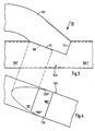
- a total of six exhaust pipes 1 to 6 are arranged on the exhaust side of a six-cylinder in-line engine, not shown, each of which is assigned to a cylinder.
- These outlet pipes 1 to 6 have the same length as possible and are combined into two groups, such that the outlet pipes 1 to 3 are brought together in a further exhaust pipe 7 and the outlet pipes 4 to 6 are brought together in a further exhaust pipe 8.
- the total cross-sectional area of the exhaust pipes 1 to 3 or 4 to 6 of each group is approximately twice as large as the cross-sectional area of the respectively assigned exhaust pipe 7 or 8.
- the further exhaust pipes 7 and 8 are in turn brought together in a common exhaust pipe 9, the cross-sectional area of which corresponds approximately to the cross-sectional area of each of the further exhaust pipes 7 and 8, i.e. the total cross-sectional area of the secondary exhaust pipes 7 and 8 is approximately twice as large as the cross-sectional area of the common exhaust pipe 9.
- the common exhaust pipe 9 can bifurcate in its further course and open into a front silencer 10, which is followed by a rear silencer 11, front silencer 10 and rear silencer 11 being connected to one another via double pipes and the rear silencer being opened to the atmosphere via a double pipe.
- This embodiment is shown in the upper right section of FIG. 1.
- the common exhaust pipe 9 can also open into the front silencer 10 ', which in turn is connected via a simple pipe to the rear silencer 11', which in this case is connected to the atmosphere via a simple exhaust pipe.
- a catalytic converter chamber 12 is arranged, in which the exhaust gases flow through a catalytic converter and, at least in part, are broken down into their elementary components.
- the catalyst chamber 12 is then in turn followed by a rear silencer 11 ′′, which in turn is connected to the atmosphere via an end pipe.
- the engine is controlled by means of a lambda probe 13, in particular with regard to the mixing ratio of the supplied fuel with air and the ignition times.
- the lambda probe 13 is arranged on a corresponding bore in the common exhaust pipe 9. This ensures that the lambda probe 13 is acted upon by the exhaust gases of all cylinders. This is all the more so as a corresponding acceleration of the exhaust gas flow occurs due to the overall cross section of the exhaust line decreasing from the exhaust pipes 1 to 6 via the further exhaust pipes 7 and 8 and the common exhaust pipe 9, and the increased flow rates thus promote intensive mixing of the exhaust gases.
- the lambda probe 13 is only a relatively short distance from the engine along the flow path of the exhaust gases and is accordingly acted upon by exhaust gases of relatively high temperature, as is favorable for optimal functioning of the lambda probe 13.
- the catalytic converter or the catalytic converter chamber 12 accommodating it can be arranged at a greater distance from the engine in order to avoid the catalytic converter being overheated when the engine is operating at full load, in particular when operating at full load and at low speed.
- the invention thus enables optimal placement of both the lambda probe 13 and the catalyst.
- the back pressure generated by the catalytic converter due to its throttling effect in the exhaust line is largely compensated by the fact that - as already mentioned - the pressure of the exhaust gases corresponding to the narrowing of the cross-section of the exhaust line from the exhaust pipes 1 to 6 via the exhaust pipes 7 and 8 and the common exhaust pipe 9 gradually decreases, with a corresponding increase in flow velocity.
- FIG. 2 correspond to the embodiments according to FIG. 1 in all essential points.
- Fig. 2 only the case of a four-cylinder in-line engine is shown, in which according to the number of cylinders only four exhaust pipes 1 to 4 are to be arranged. It is spatially easily possible to take into account the firing order of the cylinders of the engine, for example by exhaust pipes 1 and 4 or exhaust pipes 2 and 3 each opening into one of the exhaust pipes 7 and 8, for example if the first, fourth, second and third cylinders are fired in succession. Otherwise, the explanations and explanations for FIG. 1 apply analogously to FIG. 2.
- Figures 1 and 2 is shown by dashed lines, arranged within the tubes wall parts 14 that the mouth areas of the exhaust pipes 1 to 6 or the mouth areas of the further exhaust pipes 7 and 8 according to a preferred embodiment of the invention in the exhaust gas flow direction like a nozzle can or should be narrowed.
- the exhaust pipe 107 corresponds, for example, to a section of the outgoing exhaust pipe 7 in FIGS. 1 or 2, while the exhaust pipe 108 with its area 108 'is a section of the outgoing exhaust pipe 8 in FIGS. 1 and 2 and with its area 108 "is a section of the common area Exhaust pipe 9 forms in Figures 1 and 2.
- the pipe 108 which is made in one piece by bringing the pipes 107 and 108 together, has between its regions 108 'and 108 "an opening 109 which extends over approximately half the circumference. Following the opening 109, the circumferential wall of the pipe is on the side facing the exhaust gas flow direction of the opening 109 is pressed inward to form an inclined surface 110, which in the example shown forms an angle of approximately 20 ° with the tube axis. In plan view, the inclined surface 110 has approximately the shape of an ellipse half.
- the merged with the pipe 108 end of the pipe 107 is cut obliquely on its side facing the pipe 108, approximately at an angle of likewise 20 °, to the pipe axis, such that an edge 111 is formed, the contour of which when viewed in the direction of the arrow VI has approximately the same shape as the edge of the inclined surface 110 and the edges 109 "of the opening 109 which continue this edge.
- the end of the tube 107 is cut bluntly to form an edge 112 which adjoins the edge 109 ' Opening 109 fits.
- the edges 111 and 112 of the pipe 107 are welded to the edges of the inclined surface 110 and the adjoining opening edges 109 "and 109 '.
- the inclined surface 110 thus narrows both of the above-mentioned in the area where pipes 107 and 108 are brought together Pipes in the same way.
- the construction shown is characterized by high stability because one of the tubes is made in one piece.
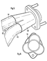
- a funnel 100 is arranged to bring together three pipes, the downstream end of which (on the right in FIG. 5) has a cross section corresponding to the exhaust gas line, not shown below.
- the funnel widens with a cloverleaf-like cross section, such that the cloverleaf cross section at the end of the funnel corresponds to the cross section of three bundled tubes, of which only tubes 101 and 102 are visible in FIG. 5.
- Each of these tubes is cut obliquely at its ends, similar to tube 107 in FIG. 3, on the circumferential side facing away from the other two tubes. This allows the tubes 101 and 102 to be pushed into the funnel 100 accordingly and welded to the same and to one another.
- the funnel thus covers the respective obliquely cut circumferential side of the tubes 101 and 102.
- the wall regions of the tubes 101 and 102 protruding into the funnel 100 together with the associated “cloverleaf” segment of the funnel 100 each form a nozzle which narrows in the flow direction, so that the exhaust gas flow coming from each of the tubes 101 and 102 before being combined with the Exhaust gas flows of the other pipes is accelerated accordingly.
- a fastening flange is arranged on the funnel 100.
- other fastening elements can optionally also be used for connection to further exhaust pipes.
- a part of the outgoing exhaust pipe can also be connected directly to the funnel 100.
- articulated connections or bellows connections can also be arranged if the exhaust parts are to be movable relative to one another.
- an exhaust pipe elbow In a six-cylinder engine with a displacement of approximately 2500 cm 3 , an exhaust pipe elbow according to the invention has the following dimensions, for example:
Landscapes
- Engineering & Computer Science (AREA)
- Chemical & Material Sciences (AREA)
- Combustion & Propulsion (AREA)
- Mechanical Engineering (AREA)
- General Engineering & Computer Science (AREA)
- Exhaust Silencers (AREA)
- Control Of Throttle Valves Provided In The Intake System Or In The Exhaust System (AREA)
Claims (14)
Priority Applications (1)
| Application Number | Priority Date | Filing Date | Title |
|---|---|---|---|
| AT86101304T ATE41041T1 (de) | 1985-02-22 | 1986-01-31 | Abgasrohrkruemmer. |
Applications Claiming Priority (2)
| Application Number | Priority Date | Filing Date | Title |
|---|---|---|---|
| DE3506183 | 1985-02-22 | ||
| DE19853506183 DE3506183A1 (de) | 1985-02-22 | 1985-02-22 | Abgasrohrkruemmer |
Publications (2)
| Publication Number | Publication Date |
|---|---|
| EP0192995A1 EP0192995A1 (fr) | 1986-09-03 |
| EP0192995B1 true EP0192995B1 (fr) | 1989-03-01 |
Family
ID=6263261
Family Applications (1)
| Application Number | Title | Priority Date | Filing Date |
|---|---|---|---|
| EP86101304A Expired EP0192995B1 (fr) | 1985-02-22 | 1986-01-31 | Collecteur d'échappement |
Country Status (3)
| Country | Link |
|---|---|
| EP (1) | EP0192995B1 (fr) |
| AT (1) | ATE41041T1 (fr) |
| DE (2) | DE3506183A1 (fr) |
Families Citing this family (9)
| Publication number | Priority date | Publication date | Assignee | Title |
|---|---|---|---|---|
| US4835965A (en) * | 1987-05-21 | 1989-06-06 | Outboard Marine Corporation | "Y" equal length exhaust system for two-cycle engines |
| DE3828599A1 (de) * | 1988-08-23 | 1990-03-08 | Bayerische Motoren Werke Ag | Abgasanlage einer mehrzylindrigen brennkraftmaschine |
| DE3838148C1 (en) * | 1988-11-10 | 1990-03-29 | Daimler-Benz Aktiengesellschaft, 7000 Stuttgart, De | Exhaust line for a spark ignition internal combustion engine |
| DE4218834C2 (de) * | 1992-06-09 | 1996-11-28 | Opel Adam Ag | Abgasanlage für einen Verbrennungsmotor |
| DE4228372C2 (de) * | 1992-08-26 | 1994-08-25 | Zeuna Staerker Kg | Rohrverzweigung, Verfahren zu ihrer Herstellung und Vorrichtung hierfür |
| DE9407812U1 (de) * | 1994-05-11 | 1994-07-21 | Zeuna-Stärker GmbH & Co KG, 86154 Augsburg | Rohrzusammenführung und Vorrichtung zu ihrer Herstellung |
| EP0733788B1 (fr) * | 1995-02-24 | 2002-07-17 | Volkswagen Aktiengesellschaft | Collecteur pour un moteur à combustion interne |
| DE19722725A1 (de) | 1997-05-30 | 1998-12-03 | Zeuna Staerker Kg | Rohrzusammenführung |
| JP6361638B2 (ja) | 2015-11-25 | 2018-07-25 | マツダ株式会社 | 多気筒エンジンの排気装置 |
Family Cites Families (6)
| Publication number | Priority date | Publication date | Assignee | Title |
|---|---|---|---|---|
| US3077071A (en) * | 1960-04-28 | 1963-02-12 | Nordberg Manufacturing Co | Exhaust system for turbocharged engine |
| US3507301A (en) * | 1966-04-21 | 1970-04-21 | Robert H Larson | Collector and method of making the same |
| US3545414A (en) * | 1969-05-21 | 1970-12-08 | Modern Tube Bending & Mfg | Exhaust header |
| US4197704A (en) * | 1976-06-11 | 1980-04-15 | Honda Giken Kogyo Kabushiki Kaisha | Exhaust manifold for internal combustion engine |
| JPS6011217B2 (ja) * | 1977-11-14 | 1985-03-23 | トヨタ自動車株式会社 | 内燃機関の基本空燃,比調整用装置 |
| DE3314839C2 (de) * | 1983-04-23 | 1986-10-16 | Werner 8510 Fürth Pedack | Krümmer-Einrichtung |
-
1985
- 1985-02-22 DE DE19853506183 patent/DE3506183A1/de not_active Withdrawn
-
1986
- 1986-01-31 EP EP86101304A patent/EP0192995B1/fr not_active Expired
- 1986-01-31 AT AT86101304T patent/ATE41041T1/de not_active IP Right Cessation
- 1986-01-31 DE DE8686101304T patent/DE3662213D1/de not_active Expired
Also Published As
| Publication number | Publication date |
|---|---|
| EP0192995A1 (fr) | 1986-09-03 |
| DE3506183A1 (de) | 1986-08-28 |
| DE3662213D1 (en) | 1989-04-06 |
| ATE41041T1 (de) | 1989-03-15 |
Similar Documents
| Publication | Publication Date | Title |
|---|---|---|
| DE2154155C2 (de) | Abgasanlage für eine Brennkraftmaschine | |
| DE4006438C2 (de) | Abgasanlage für einen Viertakt-Vierzylindermotor | |
| EP0955453A2 (fr) | Collecteur d'échappement | |
| EP0192995B1 (fr) | Collecteur d'échappement | |
| DE10333096A1 (de) | Fahrzeugabgassystem mit längenausgleichendem Schalldämpfer | |
| DE4209155C2 (de) | Auspuffsystem für einen Verbrennungsmotor | |
| DE3151130A1 (de) | Abgasschalldaempfer fuer einen zweitakt-zweizylinder-boxermotor einer kettensaege | |
| DE10144015A1 (de) | Abgasanlage für mehrzylindrige Verbrennungsmotoren | |
| DE69626648T2 (de) | Sammelstück für die primären leitungen eines auspuffkrümmers | |
| EP1457647A1 (fr) | Dispositif d'échappement d'un moteur à combustion interne | |
| EP1044325B1 (fr) | Installation d'aspiration pour une alimentation en air comburant d'un moteur a combustion interne | |
| DE2640035A1 (de) | Auspuffvorrichtung fuer verbrennungskraftmaschinen zum absaugen von sekundaerluft | |
| DE2721314B2 (de) | Kastenförmige Tragkonstruktion für einen Turbolader einer Brennkraftmaschine | |
| DE10002240B4 (de) | Vorrichtung zum Erzeugen eines obertonreichen sportlichen Auspuffgeräusches | |
| DE10008458B4 (de) | Abgassystem für ein Motorrad | |
| DE3137453A1 (de) | Ansauganordnung fuer eine brennkraftmaschine | |
| DE1035973B (de) | Abgasschalldaempfungsanlage fuer Mehrzylinder-Brennkraftmaschinen | |
| DE102004050934B4 (de) | Einlaßkrümmer | |
| DE3015444A1 (de) | Auspuffschalldaempfer | |
| DE3314839C2 (de) | Krümmer-Einrichtung | |
| DE19645619A1 (de) | Abgasleitungssystem zum Abführen von Abgas aus einem Verbrennungsmotor | |
| DE2549427C3 (de) | Abgaseinrichtung fur eine sauerstoffreiche Abgase abgebende Brennkraftmaschine | |
| DE2733302A1 (de) | Abgaskasten fuer mehrzylinder-brennkraftmaschinen, insbesondere fuer kraftfahrzeuge | |
| DE4416251C1 (de) | Auslaßkanal an einer Brennkraftmaschine | |
| DE102024129766A1 (de) | Abgasanlage mit einem Zweitakt-Motor sowie deren Verwendung |
Legal Events
| Date | Code | Title | Description |
|---|---|---|---|
| PUAI | Public reference made under article 153(3) epc to a published international application that has entered the european phase |
Free format text: ORIGINAL CODE: 0009012 |
|
| AK | Designated contracting states |
Kind code of ref document: A1 Designated state(s): AT CH DE FR GB IT LI NL SE |
|
| 17P | Request for examination filed |
Effective date: 19861004 |
|
| 17Q | First examination report despatched |
Effective date: 19870515 |
|
| ITF | It: translation for a ep patent filed | ||
| GRAA | (expected) grant |
Free format text: ORIGINAL CODE: 0009210 |
|
| AK | Designated contracting states |
Kind code of ref document: B1 Designated state(s): AT CH DE FR GB IT LI NL SE |
|
| REF | Corresponds to: |
Ref document number: 41041 Country of ref document: AT Date of ref document: 19890315 Kind code of ref document: T |
|
| REF | Corresponds to: |
Ref document number: 3662213 Country of ref document: DE Date of ref document: 19890406 |
|
| ET | Fr: translation filed | ||
| GBT | Gb: translation of ep patent filed (gb section 77(6)(a)/1977) | ||
| PLBE | No opposition filed within time limit |
Free format text: ORIGINAL CODE: 0009261 |
|
| STAA | Information on the status of an ep patent application or granted ep patent |
Free format text: STATUS: NO OPPOSITION FILED WITHIN TIME LIMIT |
|
| 26N | No opposition filed | ||
| ITTA | It: last paid annual fee | ||
| PGFP | Annual fee paid to national office [announced via postgrant information from national office to epo] |
Ref country code: DE Payment date: 19931103 Year of fee payment: 9 |
|
| PGFP | Annual fee paid to national office [announced via postgrant information from national office to epo] |
Ref country code: FR Payment date: 19931116 Year of fee payment: 9 |
|
| PGFP | Annual fee paid to national office [announced via postgrant information from national office to epo] |
Ref country code: GB Payment date: 19940114 Year of fee payment: 9 |
|
| PGFP | Annual fee paid to national office [announced via postgrant information from national office to epo] |
Ref country code: SE Payment date: 19940125 Year of fee payment: 9 Ref country code: AT Payment date: 19940125 Year of fee payment: 9 |
|
| PGFP | Annual fee paid to national office [announced via postgrant information from national office to epo] |
Ref country code: NL Payment date: 19940131 Year of fee payment: 9 |
|
| PGFP | Annual fee paid to national office [announced via postgrant information from national office to epo] |
Ref country code: CH Payment date: 19940216 Year of fee payment: 9 |
|
| EAL | Se: european patent in force in sweden |
Ref document number: 86101304.3 |
|
| PG25 | Lapsed in a contracting state [announced via postgrant information from national office to epo] |
Ref country code: LI Effective date: 19950131 Ref country code: GB Effective date: 19950131 Ref country code: CH Effective date: 19950131 Ref country code: AT Effective date: 19950131 |
|
| PG25 | Lapsed in a contracting state [announced via postgrant information from national office to epo] |
Ref country code: SE Effective date: 19950201 |
|
| PG25 | Lapsed in a contracting state [announced via postgrant information from national office to epo] |
Ref country code: NL Effective date: 19950801 |
|
| GBPC | Gb: european patent ceased through non-payment of renewal fee |
Effective date: 19950131 |
|
| PG25 | Lapsed in a contracting state [announced via postgrant information from national office to epo] |
Ref country code: FR Effective date: 19950929 |
|
| REG | Reference to a national code |
Ref country code: CH Ref legal event code: PL |
|
| NLV4 | Nl: lapsed or anulled due to non-payment of the annual fee |
Effective date: 19950801 |
|
| PG25 | Lapsed in a contracting state [announced via postgrant information from national office to epo] |
Ref country code: DE Effective date: 19951003 |
|
| EUG | Se: european patent has lapsed |
Ref document number: 86101304.3 |
|
| REG | Reference to a national code |
Ref country code: FR Ref legal event code: ST |
|
| PG25 | Lapsed in a contracting state [announced via postgrant information from national office to epo] |
Ref country code: IT Free format text: LAPSE BECAUSE OF NON-PAYMENT OF DUE FEES;WARNING: LAPSES OF ITALIAN PATENTS WITH EFFECTIVE DATE BEFORE 2007 MAY HAVE OCCURRED AT ANY TIME BEFORE 2007. THE CORRECT EFFECTIVE DATE MAY BE DIFFERENT FROM THE ONE RECORDED. Effective date: 20050131 |