EP0193045A1 - Elektrischer Uhren-Modul, ausgelegt zur Anpassung der Batterie-polarität an diejenige der Schaltung - Google Patents
Elektrischer Uhren-Modul, ausgelegt zur Anpassung der Batterie-polarität an diejenige der Schaltung Download PDFInfo
- Publication number
- EP0193045A1 EP0193045A1 EP86101875A EP86101875A EP0193045A1 EP 0193045 A1 EP0193045 A1 EP 0193045A1 EP 86101875 A EP86101875 A EP 86101875A EP 86101875 A EP86101875 A EP 86101875A EP 0193045 A1 EP0193045 A1 EP 0193045A1
- Authority
- EP
- European Patent Office
- Prior art keywords
- circuit
- pads
- printed circuit
- battery
- axis
- Prior art date
- Legal status (The legal status is an assumption and is not a legal conclusion. Google has not performed a legal analysis and makes no representation as to the accuracy of the status listed.)
- Granted
Links
Images

Classifications
-
- H—ELECTRICITY
- H01—ELECTRIC ELEMENTS
- H01M—PROCESSES OR MEANS, e.g. BATTERIES, FOR THE DIRECT CONVERSION OF CHEMICAL ENERGY INTO ELECTRICAL ENERGY
- H01M50/00—Constructional details or processes of manufacture of the non-active parts of electrochemical cells other than fuel cells, e.g. hybrid cells
- H01M50/20—Mountings; Secondary casings or frames; Racks, modules or packs; Suspension devices; Shock absorbers; Transport or carrying devices; Holders
- H01M50/204—Racks, modules or packs for multiple batteries or multiple cells
- H01M50/207—Racks, modules or packs for multiple batteries or multiple cells characterised by their shape
- H01M50/216—Racks, modules or packs for multiple batteries or multiple cells characterised by their shape adapted for button or coin cells
-
- G—PHYSICS
- G04—HOROLOGY
- G04C—ELECTROMECHANICAL CLOCKS OR WATCHES
- G04C10/00—Arrangements of electric power supplies in time-pieces
-
- H—ELECTRICITY
- H01—ELECTRIC ELEMENTS
- H01H—ELECTRIC SWITCHES; RELAYS; SELECTORS; EMERGENCY PROTECTIVE DEVICES
- H01H9/00—Details of switching devices, not covered by groups H01H1/00 - H01H7/00
- H01H9/0005—Tap change devices
- H01H9/0011—Voltage selector switches
-
- H—ELECTRICITY
- H05—ELECTRIC TECHNIQUES NOT OTHERWISE PROVIDED FOR
- H05K—PRINTED CIRCUITS; CASINGS OR CONSTRUCTIONAL DETAILS OF ELECTRIC APPARATUS; MANUFACTURE OF ASSEMBLAGES OF ELECTRICAL COMPONENTS
- H05K1/00—Printed circuits
- H05K1/02—Details
- H05K1/0286—Programmable, customizable or modifiable circuits
- H05K1/029—Programmable, customizable or modifiable circuits having a programmable lay-out, i.e. adapted for choosing between a few possibilities
-
- H—ELECTRICITY
- H05—ELECTRIC TECHNIQUES NOT OTHERWISE PROVIDED FOR
- H05K—PRINTED CIRCUITS; CASINGS OR CONSTRUCTIONAL DETAILS OF ELECTRIC APPARATUS; MANUFACTURE OF ASSEMBLAGES OF ELECTRICAL COMPONENTS
- H05K1/00—Printed circuits
- H05K1/02—Details
- H05K1/0286—Programmable, customizable or modifiable circuits
- H05K1/0295—Programmable, customizable or modifiable circuits adapted for choosing between different types or different locations of mounted components
-
- H—ELECTRICITY
- H05—ELECTRIC TECHNIQUES NOT OTHERWISE PROVIDED FOR
- H05K—PRINTED CIRCUITS; CASINGS OR CONSTRUCTIONAL DETAILS OF ELECTRIC APPARATUS; MANUFACTURE OF ASSEMBLAGES OF ELECTRICAL COMPONENTS
- H05K1/00—Printed circuits
- H05K1/02—Details
- H05K1/14—Structural association of two or more printed circuits
- H05K1/141—One or more single auxiliary printed circuits mounted on a main printed circuit, e.g. modules, adapters
-
- H—ELECTRICITY
- H05—ELECTRIC TECHNIQUES NOT OTHERWISE PROVIDED FOR
- H05K—PRINTED CIRCUITS; CASINGS OR CONSTRUCTIONAL DETAILS OF ELECTRIC APPARATUS; MANUFACTURE OF ASSEMBLAGES OF ELECTRICAL COMPONENTS
- H05K2201/00—Indexing scheme relating to printed circuits covered by H05K1/00
- H05K2201/09—Shape and layout
- H05K2201/09818—Shape or layout details not covered by a single group of H05K2201/09009 - H05K2201/09809
- H05K2201/09954—More mounting possibilities, e.g. on same place of PCB, or by using different sets of edge pads
-
- H—ELECTRICITY
- H05—ELECTRIC TECHNIQUES NOT OTHERWISE PROVIDED FOR
- H05K—PRINTED CIRCUITS; CASINGS OR CONSTRUCTIONAL DETAILS OF ELECTRIC APPARATUS; MANUFACTURE OF ASSEMBLAGES OF ELECTRICAL COMPONENTS
- H05K2201/00—Indexing scheme relating to printed circuits covered by H05K1/00
- H05K2201/10—Details of components or other objects attached to or integrated in a printed circuit board
- H05K2201/10007—Types of components
- H05K2201/10053—Switch
-
- H—ELECTRICITY
- H05—ELECTRIC TECHNIQUES NOT OTHERWISE PROVIDED FOR
- H05K—PRINTED CIRCUITS; CASINGS OR CONSTRUCTIONAL DETAILS OF ELECTRIC APPARATUS; MANUFACTURE OF ASSEMBLAGES OF ELECTRICAL COMPONENTS
- H05K2201/00—Indexing scheme relating to printed circuits covered by H05K1/00
- H05K2201/10—Details of components or other objects attached to or integrated in a printed circuit board
- H05K2201/10007—Types of components
- H05K2201/10212—Programmable component
-
- H—ELECTRICITY
- H05—ELECTRIC TECHNIQUES NOT OTHERWISE PROVIDED FOR
- H05K—PRINTED CIRCUITS; CASINGS OR CONSTRUCTIONAL DETAILS OF ELECTRIC APPARATUS; MANUFACTURE OF ASSEMBLAGES OF ELECTRICAL COMPONENTS
- H05K2203/00—Indexing scheme relating to apparatus or processes for manufacturing printed circuits covered by H05K3/00
- H05K2203/16—Inspection; Monitoring; Aligning
- H05K2203/168—Wrong mounting prevention
-
- Y—GENERAL TAGGING OF NEW TECHNOLOGICAL DEVELOPMENTS; GENERAL TAGGING OF CROSS-SECTIONAL TECHNOLOGIES SPANNING OVER SEVERAL SECTIONS OF THE IPC; TECHNICAL SUBJECTS COVERED BY FORMER USPC CROSS-REFERENCE ART COLLECTIONS [XRACs] AND DIGESTS
- Y02—TECHNOLOGIES OR APPLICATIONS FOR MITIGATION OR ADAPTATION AGAINST CLIMATE CHANGE
- Y02E—REDUCTION OF GREENHOUSE GAS [GHG] EMISSIONS, RELATED TO ENERGY GENERATION, TRANSMISSION OR DISTRIBUTION
- Y02E60/00—Enabling technologies; Technologies with a potential or indirect contribution to GHG emissions mitigation
- Y02E60/10—Energy storage using batteries
Definitions
- the present invention relates to an electronic watch module electrically connecting the battery to the watch circuit. It relates more particularly to a module making it possible to adapt the polarity of the electrodes of the battery to the polarity of the circuit supply terminals.
- the batteries used in electronic watches are all similar externally. They are made up of a metal container of cylindrical shape and a cover, also of metal, which closes the container tightly, the container and the cover being moreover electrically isolated from one another. Depending on the energy capacity of the battery, its dimensions are more or less large, but its general shape remains the same.
- the battery takes place in the watch inside a housing provided for this purpose in the plate.
- the housing which is provided with two terminals coming into contact with the electrodes, has a dimension allowing it to receive a battery of capacity corresponding to the consumption of the circuit.
- the terminals one of which may for example be in the form of a flange, are connected to the watch circuit to supply it with voltage with a determined polarity.
- the cylindrical shape of the battery also makes it possible to introduce it into the housing in two different ways, the battery cover placed at the top or at the bottom. So that the circuit is supplied with the correct polarity whatever the position of the battery in the housing, it is also known to use terminals particular shape. Of course the polarity of the battery must be well defined.
- lithium batteries have appeared on the market, having the advantage over conventional batteries of having a very low self-discharge and of presenting no risk of electrolyte leakage. If these new batteries are compatible, from the point of view of voltage, capacity and dimensions, with the requirements required for watch batteries, on the other hand, the polarity of their electrodes is opposite to those of mercury or money. Indeed, the tray of a lithium battery constitutes the negative electrode and the cover the positive electrode.
- the present invention aims to overcome this drawback by proposing an electronic watch module comprising a support and a first printed circuit which is disposed on the support and carries first and second conductive pads intended to be connected respectively to the two electrodes. a battery.
- the module is particularly remarkable in that this first circuit carries a third and a fourth conductive pads connected respectively to the two supply terminals of an electronic circuit, and in that it further comprises a second printed circuit comprising conductive pads, intended to cooperate with the first circuit on which it can occupy two determined and identifiable positions, so that, in the first position, the conductive pads of the second printed circuit connect the first pad to the third and the second to the fourth, and that, in the second position, the conductive pads of the second printed circuit connect the first pad to the fourth and the second to the third, which makes it possible to supply the electronic circuit, in the first position of the second printed circuit, by a battery whose electrodes have a given polarity and, in its second position, by a battery whose electrodes have a reverse polarity.
- the electronic watch module comprises two printed circuits cooperating together.
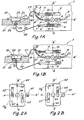
- the first circuit, referenced 1 is shown in plan in Figure lA. It comprises a first conductive pad 2 of elongated rectangular shape and a second conductive pad 3, of the same shape as the first, these two pads being arranged symmetrically with respect to an axis aa 'parallel to the long sides of the pads.
- Track 2 is extended in the direction of its length by a conductive track 4 ending in a contact 5.
- track 3 is extended by a conductive track 6 ending in a contact 7.
- Circuit 1 still carries a third rectangular conductive pad 8, the longitudinal axis of the rectangle coinciding with the axis aa ', and a fourth conductive pad 9 of the same shape and placed in the same way relative to the axis aa' as the third.
- the width of all of these areas is substantially the same, while the length of areas 8 and 9 is less than half the length of areas 2 and 3.
- the outer ends of areas 8 and 9 are moreover substantially aligned with the ends. outside of tracks 2 and 3. Tracks 8 and 9 are therefore arranged symmetrically by with respect to an axis bb 'joining the midpoints of the long sides of areas 2 and 3.
- Areas 8 and 9 are extended respectively by conductive tracks 10 and 11 leading to two supply terminals of an electronic circuit not shown, which can advantageously - - carefully to be on the first printed circuit 1.
- This one carries on the axis bb ', equidistant from the axis aa', two positioning pins 12 and 13.
- a hole 14 for receiving a fixing screw not shown.
- FIG. 1A also shows that a battery 20, silver or mercury, is placed in a housing 21 formed in the plate 22 of the watch.
- the stack is formed by a tank 23, of cylindrical shape, sealed in a sealed manner by a projecting circular cover 24.
- the tank 23 constitutes the positive electrode and the cover 24 the negative electrode of the stack.
- the housing 21, of cylindrical shape has a diameter at its upper part which is equal to the diameter of the container 23, while at its lower part its diameter is intermediate between that of the container 23 and that of the cover 24.
- a terminal 25 passing through the plate 22. This terminal, intended to come into contact with the battery cover, is isolated from the plate using an insulating sleeve 26.
- the height of the part of the housing 21 with a small diameter is such that, when the stack is placed normally, the tray at the top, its cover 24 comes into contact with the terminal 25. On the other hand, if the stack is placed the tray at the bottom, the latter cannot touch terminal.
- the terminal 25 is therefore in contact with the negative electrode and terminal 27 with the positive electrode of the battery 20 if the latter is silver or mercury.
- the battery voltage is finally transmitted to the conductive areas 2 and 3 of the first printed circuit 1 using a first electrical conductor 28, connecting the terminal 25 to the contact 7, and a second conductor 29, connecting the terminal 27 on contact 5.
- FIG. 1B is identical to FIG. 1A except that, in this case, the battery is a lithium battery 30, of the same shape as the battery 20 and having substantially the same voltage.
- This stack is also formed by a tank 31 and a cover 32, but the tank constitutes the negative electrode, while the cover constitutes the positive electrode.
- the terminals 25 and 27 therefore have a reverse polarity to that indicated in FIG. 1A.
- the second printed circuit 40 of the module according to the invention has two faces 40a and 40b respectively shown in FIGS. 2A and 2B. It has a substantially rectangular outline with a horizontal axis of symmetry xx 'and a vertical axis of symmetry yy'.
- the face 40A carries a symbol representative of the type of battery used, for example Ag for a silver battery, which is inscribed on a lug 41 extending the circuit in the direction of the axis xx '.
- This face carries a first conductive pad 42 of rectangular shape and a second conductive pad 43 of the same dimension. The long sides of these two areas are parallel to the axis yy 'and they are placed at equal distance on either side of this axis.
- Track 42 is mainly located in the upper part of circuit 40, while slightly encroaching on its lower part.
- the length of this area is slightly larger than the distance separating areas 2 and 8 of circuit 1, while its width is approximately half the length of area 8.
- Area 43 has a position symmetrical to the area 42 relative to the point of intersection of the axes xx 'and yy' and the distance which separates these two ranges, measured along the axis xx ', is substantially equal to that existing between the midpoints of ranges 8 and 9 of the circuit 1.
- a positioning hole 44 is formed on the axis yy 'of the circuit 40 at a distance equal to that which separates the pin 12 from the axis aa', the diameter of this hole being the same as that of the pin.
- a second positioning hole 45 is also located on the axis yy '. It has the same diameter as the hole 44 and occupies a symmetrical position of the latter relative to the axis xx '. Finally, a hole 46, of the same diameter as the hole 14, is formed on the circuit 40 at the intersection of the axes xx 'and yy'.
- FIG. 2B shows the face 40b of the circuit, the lug 41 of which bears the inscription Li, for designating a lithium battery.
- a third and a fourth conductive pads referenced respectively 47 and 48, of the same shapes and dimensions as the pads 42 and 43.
- the pad 47 is exactly opposite beach 42.
- beach 48 is opposite beach 43.
- the circuit 40 cooperates with the circuit 1 as follows. Assuming that the battery used in the watch is a silver battery, which corresponds to the case of FIG. 1A, the printed circuit 40 is placed on circuit 1 with the inscription Ag visible, that is to say say in the position shown in Figure 2A, so that the pin 12 engages the hole 44 and g or- sacking 13 into the hole 45. in this position, it is therefore the face 40b that takes place on circuit 1. Track 47 is then placed on tracks 2 and 8, and track 48 on tracks 3 and 9, as indicated by the dotted line in FIG. 1A. The good contact between the pads and the maintenance of the circuits is ensured by a fixing screw not shown, passing through the holes 14 and 46 and tightening the two circuits against each other. Track 10 is thus connected to the positive electrode of battery 20 and track 11 to its negative electrode. It will be assumed that this polarity of tracks 10 and 11 corresponds to the polarity of the supply terminals of the electronic circuit, not shown, to which they are connected.
- FIG. 3 shows, in a perspective view, another embodiment of the module according to the invention. Taking up little space, this version is particularly well suited to small-scale watchmaking applications.
- the plate of a watch which carries, fixed on one of its faces, a flexible printed circuit 50 on which can advantageously take place, for example, an integrated circuit and various components not shown.
- the circuit 50 is not entirely fixed on the plate 22, but its end 51 can be raised, as shown in FIG. 3.
- This end constitutes a printed circuit identical to the first printed circuit 1 already described. Its face opposite the plate 22 carries the conductive pads 2, 3, 8 and 9 already mentioned. In this end are, in addition, made the hole 14 and an opening 52.
- a housing 53 intended to receive the printed circuit 40, represented in the position corresponding to the use of a silver or mercury battery, with the symbol Ag visible.
- the contour of the housing 53 corresponds exactly to that of the circuit 40, which makes the use of pins 12, 13 and holes 44, 45 superfluous.
- the positioning hole 46 which is extended by a no screw in plate 22.
- the other face of the circuit 40 carries the symbol Li and tracks 42 and 43, not visible, intended to come into contact with tracks 3, 8 respectively and 2, 9.
- the circuit 40 being placed in its housing in the position corresponding to the type of battery chosen, the end 51 of the flexible film 50 can be folded against the plate 22, revealing the symbol of the battery through the opening 52.
- the conductive areas of the two printed circuits then come into contact, establishing the desired electrical connections.
- the two circuits are firmly held against each other using a screw (not shown) fixed in the plate 22 through the holes 14 and 46.
Landscapes
- Engineering & Computer Science (AREA)
- Microelectronics & Electronic Packaging (AREA)
- Chemical Kinetics & Catalysis (AREA)
- General Physics & Mathematics (AREA)
- Physics & Mathematics (AREA)
- Chemical & Material Sciences (AREA)
- Power Engineering (AREA)
- Electrochemistry (AREA)
- General Chemical & Material Sciences (AREA)
- Electric Clocks (AREA)
- Electromechanical Clocks (AREA)
- Battery Mounting, Suspending (AREA)
- Amplifiers (AREA)
Applications Claiming Priority (2)
| Application Number | Priority Date | Filing Date | Title |
|---|---|---|---|
| CH81485A CH658766GA3 (de) | 1985-02-22 | 1985-02-22 | |
| CH814/85 | 1985-02-22 |
Publications (2)
| Publication Number | Publication Date |
|---|---|
| EP0193045A1 true EP0193045A1 (de) | 1986-09-03 |
| EP0193045B1 EP0193045B1 (de) | 1989-06-21 |
Family
ID=4195814
Family Applications (1)
| Application Number | Title | Priority Date | Filing Date |
|---|---|---|---|
| EP86101875A Expired EP0193045B1 (de) | 1985-02-22 | 1986-02-14 | Elektrischer Uhren-Modul, ausgelegt zur Anpassung der Batterie-polarität an diejenige der Schaltung |
Country Status (5)
| Country | Link |
|---|---|
| US (1) | US4632571A (de) |
| EP (1) | EP0193045B1 (de) |
| JP (1) | JPS61195561A (de) |
| CH (1) | CH658766GA3 (de) |
| DE (1) | DE3664070D1 (de) |
Cited By (4)
| Publication number | Priority date | Publication date | Assignee | Title |
|---|---|---|---|---|
| CH681130GA3 (en) * | 1991-07-12 | 1993-01-29 | Small electronic watch e.g. wrist watch - has voltage divider in opening on base side of watch movement and 3 volt battery arranged between base and watch movement | |
| FR2687036A1 (fr) * | 1992-02-04 | 1993-08-06 | Alcatel Business Systems | Dispositif a commande manuelle devant assurer au moins deux fonctions differentes. |
| WO2011117053A1 (de) * | 2010-03-24 | 2011-09-29 | Epcos Ag | Frontendmodul und verfahren zum betrieb in unterschiedlichen schaltungsumgebungen |
| WO2012107463A1 (de) * | 2011-02-09 | 2012-08-16 | Continental Automotive Gmbh | Anordnung zur elektrischen kontaktierung von elektrischen bauelementen |
Families Citing this family (1)
| Publication number | Priority date | Publication date | Assignee | Title |
|---|---|---|---|---|
| JP3610494B2 (ja) * | 2002-06-26 | 2005-01-12 | オリオン電機株式会社 | プリント基板の極性表示 |
Citations (5)
| Publication number | Priority date | Publication date | Assignee | Title |
|---|---|---|---|---|
| DE1116917B (de) * | 1958-09-27 | 1961-11-09 | Erich Zillmer | Netzspannungsumschalter fuer elektrisch betriebene Bildwerfer |
| DE1945678A1 (de) * | 1969-09-10 | 1971-03-11 | Unomat Gmbh & Co Kg | Netzspannungsumschalter |
| DE2749543A1 (de) * | 1976-12-03 | 1978-06-08 | Itt Ind Gmbh Deutsche | Elastische gedruckte schaltung |
| US4181389A (en) * | 1978-09-13 | 1980-01-01 | General Electric Company | Tap changing electrical connector for static trip circuit breakers |
| EP0019836A1 (de) * | 1979-05-31 | 1980-12-10 | Siemens Aktiengesellschaft | Einpolige mehrstufige Umschalteinrichtung für auf Printplatten gedruckte Schaltungen |
Family Cites Families (3)
| Publication number | Priority date | Publication date | Assignee | Title |
|---|---|---|---|---|
| JPS54145578A (en) * | 1978-05-04 | 1979-11-13 | Citizen Watch Co Ltd | Battery vlock structure for electronic wristwatches |
| CH638653B (fr) * | 1979-08-21 | Ebauchesfabrik Eta Ag | Dispositif de maintien d'une pile dans une montre-bracelet electronique. | |
| US4478524A (en) * | 1980-04-01 | 1984-10-23 | Citizen Watch Company Limited | Arrangement of analog-type electronic wristwatch |
-
1985
- 1985-02-22 CH CH81485A patent/CH658766GA3/fr unknown
-
1986
- 1986-02-14 EP EP86101875A patent/EP0193045B1/de not_active Expired
- 1986-02-14 DE DE8686101875T patent/DE3664070D1/de not_active Expired
- 1986-02-21 US US06/831,765 patent/US4632571A/en not_active Expired - Fee Related
- 1986-02-21 JP JP61035375A patent/JPS61195561A/ja active Granted
Patent Citations (5)
| Publication number | Priority date | Publication date | Assignee | Title |
|---|---|---|---|---|
| DE1116917B (de) * | 1958-09-27 | 1961-11-09 | Erich Zillmer | Netzspannungsumschalter fuer elektrisch betriebene Bildwerfer |
| DE1945678A1 (de) * | 1969-09-10 | 1971-03-11 | Unomat Gmbh & Co Kg | Netzspannungsumschalter |
| DE2749543A1 (de) * | 1976-12-03 | 1978-06-08 | Itt Ind Gmbh Deutsche | Elastische gedruckte schaltung |
| US4181389A (en) * | 1978-09-13 | 1980-01-01 | General Electric Company | Tap changing electrical connector for static trip circuit breakers |
| EP0019836A1 (de) * | 1979-05-31 | 1980-12-10 | Siemens Aktiengesellschaft | Einpolige mehrstufige Umschalteinrichtung für auf Printplatten gedruckte Schaltungen |
Cited By (5)
| Publication number | Priority date | Publication date | Assignee | Title |
|---|---|---|---|---|
| CH681130GA3 (en) * | 1991-07-12 | 1993-01-29 | Small electronic watch e.g. wrist watch - has voltage divider in opening on base side of watch movement and 3 volt battery arranged between base and watch movement | |
| FR2687036A1 (fr) * | 1992-02-04 | 1993-08-06 | Alcatel Business Systems | Dispositif a commande manuelle devant assurer au moins deux fonctions differentes. |
| WO2011117053A1 (de) * | 2010-03-24 | 2011-09-29 | Epcos Ag | Frontendmodul und verfahren zum betrieb in unterschiedlichen schaltungsumgebungen |
| US9084286B2 (en) | 2010-03-24 | 2015-07-14 | Epcos Ag | Front end module and method of operation in different circuit environments |
| WO2012107463A1 (de) * | 2011-02-09 | 2012-08-16 | Continental Automotive Gmbh | Anordnung zur elektrischen kontaktierung von elektrischen bauelementen |
Also Published As
| Publication number | Publication date |
|---|---|
| US4632571A (en) | 1986-12-30 |
| JPH0548577B2 (de) | 1993-07-21 |
| JPS61195561A (ja) | 1986-08-29 |
| EP0193045B1 (de) | 1989-06-21 |
| DE3664070D1 (en) | 1989-07-27 |
| CH658766GA3 (de) | 1986-12-15 |
Similar Documents
| Publication | Publication Date | Title |
|---|---|---|
| EP1828786A1 (de) | Vorrichtung zur messung eines stromflusses in einem kabel | |
| FR2550014A1 (fr) | Monture de pile electrique, pour piles plates | |
| EP0156146B1 (de) | Piezoelektrischer Oszillator | |
| EP0074006A1 (de) | Elektronische Gelenkarmbanduhr sowie Verfahren zur Herstellung einer Dichtung für diese Gelenkarmbanduhr | |
| FR2492214A1 (fr) | Dispositif de controle pour plaques de circuits imprimes | |
| FR2734071A1 (fr) | Carte de paiement electronique a module interchangeable | |
| CA2948387C (fr) | Dispositif cutane, notamment generateur d'impulsions pour l'electrostimulation | |
| EP0209717B1 (de) | Batteriekammer für elektronische Uhr | |
| FR2538954A1 (fr) | Batterie rechargeable avec borne de charge annulaire | |
| WO2015177682A1 (fr) | Connecteur electrique notamment pour dispositif cutane | |
| CA1038448A (fr) | Generateur electrochimique | |
| EP0193045A1 (de) | Elektrischer Uhren-Modul, ausgelegt zur Anpassung der Batterie-polarität an diejenige der Schaltung | |
| EP0228741A1 (de) | Testvorrichtung für ein Gehäuse ohne Kontaktnadeln, versehen mit einem mit Hochfrequenz arbeitenden Chip mit integrierter Schaltung | |
| BE1014448A3 (fr) | Boitier pourvu de bornes de connexion. | |
| EP0778666A1 (de) | Piezoelektrischer Resonator | |
| FR2683397A1 (fr) | Douille electrique pour interconnecter des circuits sur une puce et des circuits sur un substrat. | |
| EP4162564A1 (de) | Verbindungselement zum verbinden zweier akkumulatoren | |
| EP2365288B1 (de) | Konfigurierbare Detektiervorrichtung | |
| FR2627612A1 (fr) | Appareil de signalisation optique a tube lumineux | |
| FR2762145A1 (fr) | Procede et dispositif de mise en contact d'une patte avec un ruban conducteur | |
| FR2578103A1 (fr) | Boite a piles, notamment a usage militaire | |
| FR2479638A1 (fr) | Support de composant electronique pour carte de cablage | |
| WO2005050227A1 (fr) | Capteur de mesure a liaisons conductrices sans raideur et procede de fabrication | |
| FR2738952A1 (fr) | Disjoncteur de protection contre les fuites a la masse | |
| FR2484147A1 (fr) | Batteries de generateurs electrochimiques du type bouton |
Legal Events
| Date | Code | Title | Description |
|---|---|---|---|
| PUAI | Public reference made under article 153(3) epc to a published international application that has entered the european phase |
Free format text: ORIGINAL CODE: 0009012 |
|
| AK | Designated contracting states |
Kind code of ref document: A1 Designated state(s): DE FR GB |
|
| 17P | Request for examination filed |
Effective date: 19861201 |
|
| 17Q | First examination report despatched |
Effective date: 19880210 |
|
| GRAA | (expected) grant |
Free format text: ORIGINAL CODE: 0009210 |
|
| AK | Designated contracting states |
Kind code of ref document: B1 Designated state(s): DE FR GB |
|
| REF | Corresponds to: |
Ref document number: 3664070 Country of ref document: DE Date of ref document: 19890727 |
|
| GBT | Gb: translation of ep patent filed (gb section 77(6)(a)/1977) | ||
| PGFP | Annual fee paid to national office [announced via postgrant information from national office to epo] |
Ref country code: GB Payment date: 19900131 Year of fee payment: 5 |
|
| PGFP | Annual fee paid to national office [announced via postgrant information from national office to epo] |
Ref country code: FR Payment date: 19900215 Year of fee payment: 5 |
|
| PGFP | Annual fee paid to national office [announced via postgrant information from national office to epo] |
Ref country code: DE Payment date: 19900220 Year of fee payment: 5 |
|
| PLBE | No opposition filed within time limit |
Free format text: ORIGINAL CODE: 0009261 |
|
| 26N | No opposition filed | ||
| PG25 | Lapsed in a contracting state [announced via postgrant information from national office to epo] |
Ref country code: GB Effective date: 19910214 |
|
| GBPC | Gb: european patent ceased through non-payment of renewal fee | ||
| PG25 | Lapsed in a contracting state [announced via postgrant information from national office to epo] |
Ref country code: FR Effective date: 19911031 |
|
| PG25 | Lapsed in a contracting state [announced via postgrant information from national office to epo] |
Ref country code: DE Effective date: 19911101 |
|
| REG | Reference to a national code |
Ref country code: FR Ref legal event code: ST |