EP0193088A2 - Ecran de projection par transparence - Google Patents
Ecran de projection par transparence Download PDFInfo
- Publication number
- EP0193088A2 EP0193088A2 EP86102122A EP86102122A EP0193088A2 EP 0193088 A2 EP0193088 A2 EP 0193088A2 EP 86102122 A EP86102122 A EP 86102122A EP 86102122 A EP86102122 A EP 86102122A EP 0193088 A2 EP0193088 A2 EP 0193088A2
- Authority
- EP
- European Patent Office
- Prior art keywords
- screen units
- screen
- sub
- units
- holder plates
- Prior art date
- Legal status (The legal status is an assumption and is not a legal conclusion. Google has not performed a legal analysis and makes no representation as to the accuracy of the status listed.)
- Granted
Links
- 230000005540 biological transmission Effects 0.000 title claims abstract description 17
- 230000004304 visual acuity Effects 0.000 description 4
- 239000011347 resin Substances 0.000 description 3
- 229920005989 resin Polymers 0.000 description 3
- PPBRXRYQALVLMV-UHFFFAOYSA-N Styrene Chemical compound C=CC1=CC=CC=C1 PPBRXRYQALVLMV-UHFFFAOYSA-N 0.000 description 2
- XAGFODPZIPBFFR-UHFFFAOYSA-N aluminium Chemical compound [Al] XAGFODPZIPBFFR-UHFFFAOYSA-N 0.000 description 2
- 229910052782 aluminium Inorganic materials 0.000 description 2
- 229920003002 synthetic resin Polymers 0.000 description 2
- 239000000057 synthetic resin Substances 0.000 description 2
- 239000004925 Acrylic resin Substances 0.000 description 1
- 229920000178 Acrylic resin Polymers 0.000 description 1
- 229910018085 Al-F Inorganic materials 0.000 description 1
- 229910018179 Al—F Inorganic materials 0.000 description 1
- 229910000831 Steel Inorganic materials 0.000 description 1
- BZHJMEDXRYGGRV-UHFFFAOYSA-N Vinyl chloride Chemical compound ClC=C BZHJMEDXRYGGRV-UHFFFAOYSA-N 0.000 description 1
- 229920001893 acrylonitrile styrene Polymers 0.000 description 1
- 239000000853 adhesive Substances 0.000 description 1
- 230000001070 adhesive effect Effects 0.000 description 1
- 238000010276 construction Methods 0.000 description 1
- 238000004519 manufacturing process Methods 0.000 description 1
- 229920005668 polycarbonate resin Polymers 0.000 description 1
- 239000004431 polycarbonate resin Substances 0.000 description 1
- SCUZVMOVTVSBLE-UHFFFAOYSA-N prop-2-enenitrile;styrene Chemical compound C=CC#N.C=CC1=CC=CC=C1 SCUZVMOVTVSBLE-UHFFFAOYSA-N 0.000 description 1
- 239000007787 solid Substances 0.000 description 1
- 239000010959 steel Substances 0.000 description 1
- 230000000007 visual effect Effects 0.000 description 1
- 238000003466 welding Methods 0.000 description 1
Images



Classifications
-
- G—PHYSICS
- G03—PHOTOGRAPHY; CINEMATOGRAPHY; ANALOGOUS TECHNIQUES USING WAVES OTHER THAN OPTICAL WAVES; ELECTROGRAPHY; HOLOGRAPHY
- G03B—APPARATUS OR ARRANGEMENTS FOR TAKING PHOTOGRAPHS OR FOR PROJECTING OR VIEWING THEM; APPARATUS OR ARRANGEMENTS EMPLOYING ANALOGOUS TECHNIQUES USING WAVES OTHER THAN OPTICAL WAVES; ACCESSORIES THEREFOR
- G03B21/00—Projectors or projection-type viewers; Accessories therefor
- G03B21/54—Accessories
- G03B21/56—Projection screens
- G03B21/60—Projection screens characterised by the nature of the surface
- G03B21/62—Translucent screens
- G03B21/625—Lenticular translucent screens
-
- H—ELECTRICITY
- H04—ELECTRIC COMMUNICATION TECHNIQUE
- H04N—PICTORIAL COMMUNICATION, e.g. TELEVISION
- H04N9/00—Details of colour television systems
- H04N9/12—Picture reproducers
- H04N9/31—Projection devices for colour picture display, e.g. using electronic spatial light modulators [ESLM]
- H04N9/3141—Constructional details thereof
- H04N9/3147—Multi-projection systems
Definitions
- This invention relates to a transmission type projection screen apparatus and relates in particular to a multi-sereen apparatus in which plural transmission screen units are closely arranged in a horizontal and/or vertical directions in combination with plural projectors so as to constitute a large projection screen system.
- Fig.7 shows a conventional transmission type projection screen having a circular Fresnel lens lla and a lenticular lens 12a at its opposite sides, which are made essentially of a transparent synthetic resin such as acrylic resin, vinyl chloride resin, styrene resin, polycarbonate resin, acrylonitrile-styrene copolymerized resin or the like as one body. Since relative positions of the lenses lla, 12a can be precisely maintained, such a projection screen has been used in practice. However, it is difficult to manufacture a large size of screen.
- a transparent synthetic resin such as acrylic resin, vinyl chloride resin, styrene resin, polycarbonate resin, acrylonitrile-styrene copolymerized resin or the like
- Fig.8 shows another conventional projection screen composed of two sheets such as a combination of a Fresnel lens sheet llb and a lenticular lens sheet 12b which are separately made of one of the above-stated synthetic resins and adhered to each other.
- a broad Fresnel lens sheet cannot be manufactured, it cannot be practically used in case of a large screen.
- the object of this invention is to provide a transmission type projection multi-screen apparatus which can have a large and/or broad projection surface on which only minor seams appear.
- a transmission type projection multi-screen apparatus comprising a frame, a plurality of transmission type screen units closely arranged in the frame thereby to form a multi-screen, a plurality of projectors at the rear of the screen units for projecting lights of a picture image to the screen units, respectively, and means fixed to the frame for supporting the screen units, the supporting means being placed substantially in a dead angle of the lights.
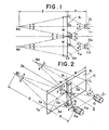
- two transmission type screen units A 1 , A 2 are closely arranged in a horizontal row so as to form a flat projection surface.
- Two projectors L 1 , L 2 are positioned at the rear of the screen units A 1 , A 2 and project partial lights of a picture image to the screen units A 1 , A 2 , respectively.
- the screen units A 1 , A 2 each has a width W.
- a projection distance P is a distance between projection lenses O 1 , 03 of the projectors L1 , L2 and points 0 2 , O 4 of the screen units A 1 , A 2 .
- a viewing distance D is a distance between the points O 2 , 04 of the screen units A 1 , A 2 and typical points AU of viewers who are in front of the screen units A 1 , A 2 ,
- a line Z 1 -Z 2 passes the point C 0 and is at a right angle to both the line X 1 -X 2 and the line Y 1 -Y 2 .
- Each projection light bundle angle of the projection lenses p 1 , 0 3 is 2 x.
- Each viewing angle of the viewers is 2y.
- the angle O 1 C 0 Z 1 is x.
- the angle 0 3 C 0 Z 1 is x. Therefore, a dead angle of the projection lights from the projectors L 1 , L 2 is 2x at a joint portion of the screen units A 1 , A 2 .
- the angle AU C o Z 2 is Y.
- a support Ta of a triangular section having a tip angle of 2x or less is placed whithin a V -shaped space formed between the adjacent screen units A 1 , A 2 corresponding to the dead angle 2x for supporting the adjacent screen units A 1 , A 2 whereby the support Ta cannot be easily seen from the viewers.
- two transmission type screen units A3, A4 are closely arranged in a vertical row so as to form a flat projection surface.
- Two projectors L 3 , L 4 are placed at the rear of the screen units A 1 , A 2 and project partical lights of a picture image to the screen units A3, A 4 , respectively.
- the screen units A3, A 4 each has a height H.
- a projection distance P is a distance between projection lenses O 11 , 012 of the projectors L 3 , L 4 and points O 12 , 0 14 of the screen units A3, A 4 .
- a viewing distance D is a distance between the points O 12' O 14 of the screen units A3, A4 and typical points AU of viewers who are in front of the screen units A3, A 4 .
- a line passing the points 0 12 , O 14 intersects each front surface of the screen units A3, A4 at points C 10 , C 11' C 121 which point C 0 is common to the screen units A 3 , A 4 , the points C 11 , C 10 , C 12 are in a line X 11 -X 12 passing each vertical center of the screen units A3, A4 while a line Y 11 -Y 12 is a horizontal line along a seam formed between the adjacent screen units A3, A 4 .
- a line Z 11 -Z 12 passes the point C 10 and is at a right angle to both the line X 11 -X 12 and the line Y 11 -Y 12 .
- Each projection light bundle angle of the projectors L 3 , L 4 is 2x while a viewing angle of the viewers is 2y.
- the angle O 11 C 10 Z 11 is x
- the angle O 13 C 10 Z 11 is x.
- a dead angle of the projection lights from the projectors L 3 , L 4 is 2x at a joint portion of the screen units A3, A 4 .
- the angle AU C 10 Z 12 is y.
- a support Tb of a triangular section having a tip angle of 2x or less is placed whithin the dead angle 2x for supporting the screen units A3, A4 whereby the support Tb cannot be easily seen from the viewers.
- two transmission type screen units A 1 , A 2 are closely arranged along a horizontal imagined circle at the same distance D from a typical viewer AU in front of the screen units A 1 , A 2 and so as to form a bent projection surface.
- Two projectors L 1 , L 2 project partial lights of a picture image to the screen units A 1 , A 2 , respectively, with a projection distance P.
- a half of a projection light bundle angle from the projectors L l , L2 is x and a half of a viewing angle from the viewer is y
- a dead angle of the lights from the projectors L 1 , L 2 is 2(x+y) at a joint portion of the screen units A 1 , A 2 .
- a support Tc of a triangular section having a tip angle of 2(x+y) or less is placed whithin the dead angle 2(x+y) for supporting the screen units A 1 , A 2 whereby the support Tc cannot be easily seen from the viewer.
- two screen units A 1 , A 2 can be arranged along a vertical circle or in a height direction at the same distance from a viewer as in the embodiment of Fig.5.
- a diagonal line thereof has a length of about 2,000 mm.
- the projection distance P is selected to be equal to the length of the diagonal line, that is, about 2,000 mm.
- X is about 24 degrees.
- the dead angle is about 48 degrees so that the support Ta can have a large tip angle so as to provide a high structural strength. It can be also said in the embodiments of Figs.3 to 5.
- the supports Ta, Tb or T c can be composed of two halves each having a tip angle of x or (x+y).
- Figs.6A and 6B show a further embodiment of this invention essentially corresponding to the embodiment of Figs.1 and 2.
- Two transmission type screen units A 1 , A2 are closely joined at their side edges and supported by a support 10 and a frame 11 which are joined by two U-shaped connectors 12.
- the support 10 is a triangular post placed whithin a dead angle (2x) of projection lights from two projectors (not shown) placed at the rear of the screen units A 1 , A 2 .
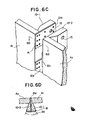
- Figs.6C and 6D show a joint portion of a further embodiment of this invention.
- Two transmission type rectangular screen units All A 2 are closely arranged at their side edges and supported by two supports 10-1, 10-2 and plural holder plates 13a, 13b which are fixedly joined to each other by screws 14.
- the holder plates 13a, 13b are also fixed to the opposite side edges of the screen units A 1 , A 2 , respectively, by means of the screws 14.
- the screen unit A 1 is fixed to the support 10-1 by means of the holder plates 13a while the screen unit A 2 is fixed to the support 10-2 by means of the holder plates 13b.
- Those supports 10-1, 10-2 are fastened by a bolt 16 set through each hole 15 of the supports 10-1, 10 - 2.
- the holder plates 13a, 13b are positioned one after the other along the side edges of the screen units A l , A 2 .
- the supports 10-1, 10-2 and a majority of the holder plates 13a, 13b are positioned within the dead angle 2x of the projection lights from projectors (not shown) placed at the rear of the screen units A l , A 2 as in the embodiment of Figs. 1 and 2.
- each front end surface of the holder plates 13a, 13b appears on a multi-screen projection surface.
- a thickness of the front end of the holder plates 13a, 13b can be limited to several milimeters.
- Fig.6E shows another embodiment of this invention which is similar to the embodiment of Figs.6C and 6D except a construction of the screen units Al, A2.
- the screen units A 1 , A 2 are composed of lenticular lenses A 1 -R, A 2-R joined directly to each other at their side edge and Fresnel lenses A l -F, A 2 -F joined indirectly through the holder plates 13a, 13b whereby the front ends of the holder plates 13a, 13b do not appear on a multi-screen projection surface.
- the holder plates 13a, 13b are inserted in a narrow groove of a channel shape formed in the adjacent Fresnel lenses.
- the supports 10-1, 10-2 and the holder plates 13a, 13b are completely positioned within the dead angle 2x of projection lights from projectors (not shown) placed at the rear of the screen units.
- the supports 10-1, 10-2 and their related members shown in Figs.6A to 6E can be also applied to the embodiments of Figs.3 to 5 as well as any other multi-screen apparatus such as a large multi-screen apparatus which is, for example, composed of 9 screen units supported by plural supports of a lattice form in a rectangular frame.
- the supports may be solid or hollow in any desired shape and made of aluminum or steel. They are to be joined to each other and also to the frame by adhesives, welding or any other fixing means.
- the width of a seam formed between the adjacent screen units A l and A 2 , A3 and A4 is limited to resolving powers of viewers' eyes.
- the visual angle of such resolving powers is 0.00029.
- resolving powers can be shown with respect to distances between viewers' eyes and a multi-screen as follows:
- the supports and their related elements appear on the multi-screen projection surface, they do not obstruct the view in case the width of them is less than a resolving power.
- a broad multi-screen apparatus having a total width of 18,000 mm will be explained as an example.
- Ten screen units each having a width of 1,800 mm are closely arranged along an imagined circle having a radius equal to the viewing distance D as in Fig. 5.
- Ten projectors are set at the rear of the ten screen units, respectively.
- the projection lenses of the projectors and a typical viewer are positioned in a conjugate relation to each other by the field lenses (Fresnel lenses) of the screen units, Thus, the viewer is in front of all screen units.
- Each projection light bundle is uniformly distributed in a lateral direction by each directional lenticular lenses of the screen units.
- An image formed by each projection lenses of the projectors functions as a secondary light source and is distributed by the corresponding lenticular lens thereof in a predetermined manner. It takes place through the whole width of the broad multi-screen.
- Plural screen units can be closely arranged along a circle having a radius larger than that of Fig.5.
- means for supporting the screen units does not obstruct the view because the supporting means is placed substantially within a dead angle of projection lights from the projectors. Viewers in front of the screen units see only very minor seams between the adjacent screen units. Therefore, commercial values of a multi-screen apparatus according to this invention are remarkable particularly in case of movie-like pictures including quick motion pictures.
Landscapes
- Physics & Mathematics (AREA)
- General Physics & Mathematics (AREA)
- Engineering & Computer Science (AREA)
- Multimedia (AREA)
- Signal Processing (AREA)
- Transforming Electric Information Into Light Information (AREA)
- Projection Apparatus (AREA)
- Overhead Projectors And Projection Screens (AREA)
Applications Claiming Priority (4)
| Application Number | Priority Date | Filing Date | Title |
|---|---|---|---|
| JP3449085A JPS61194433A (ja) | 1985-02-25 | 1985-02-25 | 大画面用透過型スクリ−ンの構成法 |
| JP34490/85 | 1985-02-25 | ||
| JP21098/86 | 1986-02-04 | ||
| JP2109886A JPS62180345A (ja) | 1986-02-04 | 1986-02-04 | 大画面用透過型スクリ−ンの構成法 |
Publications (3)
| Publication Number | Publication Date |
|---|---|
| EP0193088A2 true EP0193088A2 (fr) | 1986-09-03 |
| EP0193088A3 EP0193088A3 (en) | 1988-01-07 |
| EP0193088B1 EP0193088B1 (fr) | 1989-05-31 |
Family
ID=26358117
Family Applications (1)
| Application Number | Title | Priority Date | Filing Date |
|---|---|---|---|
| EP86102122A Expired EP0193088B1 (fr) | 1985-02-25 | 1986-02-19 | Ecran de projection par transparence |
Country Status (3)
| Country | Link |
|---|---|
| US (1) | US4668046A (fr) |
| EP (1) | EP0193088B1 (fr) |
| DE (1) | DE3663749D1 (fr) |
Cited By (4)
| Publication number | Priority date | Publication date | Assignee | Title |
|---|---|---|---|---|
| EP0514045A1 (fr) * | 1991-05-13 | 1992-11-19 | Hughes Aircraft Company | Dôme à plusieures facettes pour projection par transparence |
| EP0599272A1 (fr) * | 1992-11-25 | 1994-06-01 | Sony Corporation | Projecteur d'images |
| GB2346981A (en) * | 1998-11-09 | 2000-08-23 | Seos Displays Ltd | A display structure comprising a plurality of separate screens |
| CN106527024A (zh) * | 2016-12-16 | 2017-03-22 | 广东威创视讯科技股份有限公司 | 一种边缘融合无缝拼接显示系统及菲涅尔透镜及通过短焦投影机模拟长焦投影机的方法 |
Families Citing this family (11)
| Publication number | Priority date | Publication date | Assignee | Title |
|---|---|---|---|---|
| JPS6488531A (en) * | 1987-09-30 | 1989-04-03 | Hitachi Ltd | Back surface projection type device |
| JPH0416485U (fr) * | 1990-05-30 | 1992-02-10 | ||
| JP3085726B2 (ja) * | 1991-04-19 | 2000-09-11 | 株式会社日立製作所 | マルチプロジェクション装置 |
| US5103339A (en) * | 1991-05-31 | 1992-04-07 | Draper Shade & Screen Co., Inc. | Rear projection screen multi-panel connector assembly |
| US5317449A (en) * | 1992-04-23 | 1994-05-31 | Pioneer Electronic Corporation | Projection television set |
| US5673145A (en) * | 1995-03-24 | 1997-09-30 | Wilson; Robert M. | Rear projection screen multi-panel connection system |
| JPH09189969A (ja) * | 1996-01-08 | 1997-07-22 | Mitsubishi Electric Corp | スクリーンの取り付け構造 |
| CA2256871A1 (fr) * | 1998-12-22 | 2000-06-22 | Geoff Gosling | Methode de soutien d'un ou plusieurs retroprojecteurs sans discontinuite |
| USD430189S (en) * | 1999-03-03 | 2000-08-29 | 3M Innovative Properties Company | Integrated projection system |
| US6327082B1 (en) * | 1999-06-08 | 2001-12-04 | Stewart Filmscreen Corporation | Wedge-shaped molding for a frame of an image projection screen |
| CN106647130B (zh) * | 2017-03-07 | 2018-09-28 | 海信集团有限公司 | 背投影拼接单元、系统及背投影拼接单元调节方法 |
Family Cites Families (1)
| Publication number | Priority date | Publication date | Assignee | Title |
|---|---|---|---|---|
| US4473355A (en) * | 1983-06-30 | 1984-09-25 | Messerschmitt-Boelkow-Blohm Gesellschaft Mit Beschraenkter Haftung | Visual simulator and display screen for said simulator |
-
1986
- 1986-02-19 DE DE8686102122T patent/DE3663749D1/de not_active Expired
- 1986-02-19 EP EP86102122A patent/EP0193088B1/fr not_active Expired
- 1986-02-24 US US06/832,127 patent/US4668046A/en not_active Expired - Fee Related
Cited By (5)
| Publication number | Priority date | Publication date | Assignee | Title |
|---|---|---|---|---|
| EP0514045A1 (fr) * | 1991-05-13 | 1992-11-19 | Hughes Aircraft Company | Dôme à plusieures facettes pour projection par transparence |
| EP0599272A1 (fr) * | 1992-11-25 | 1994-06-01 | Sony Corporation | Projecteur d'images |
| GB2346981A (en) * | 1998-11-09 | 2000-08-23 | Seos Displays Ltd | A display structure comprising a plurality of separate screens |
| CN106527024A (zh) * | 2016-12-16 | 2017-03-22 | 广东威创视讯科技股份有限公司 | 一种边缘融合无缝拼接显示系统及菲涅尔透镜及通过短焦投影机模拟长焦投影机的方法 |
| CN106527024B (zh) * | 2016-12-16 | 2019-01-18 | 广东威创视讯科技股份有限公司 | 一种边缘融合无缝拼接显示系统及菲涅尔透镜及通过短焦投影机模拟长焦投影机的方法 |
Also Published As
| Publication number | Publication date |
|---|---|
| US4668046A (en) | 1987-05-26 |
| EP0193088B1 (fr) | 1989-05-31 |
| DE3663749D1 (en) | 1989-07-06 |
| EP0193088A3 (en) | 1988-01-07 |
Similar Documents
| Publication | Publication Date | Title |
|---|---|---|
| EP0193088A2 (fr) | Ecran de projection par transparence | |
| US5206760A (en) | Multiprojection apparatus | |
| US5579164A (en) | Spatially multiplexed image display system | |
| US7154675B2 (en) | Image display apparatus | |
| US4984871A (en) | Optical rear projection screen hanger assembly | |
| EP0834766B1 (fr) | Ecran de projection fonctionnant en transmission | |
| JPS5891424A (ja) | 符号プロジエクタ−装置のレンズ構造物 | |
| AU671140B2 (en) | Method and arrangement for optically representing information | |
| US6574040B1 (en) | Method and apparatus for supporting one or more seamless rear projector screens | |
| JP2941292B2 (ja) | 背面投写形装置 | |
| US6324000B1 (en) | Seam between adjacent visualization screens | |
| JP3478964B2 (ja) | 円弧形マルチビジョン | |
| JPH09146171A (ja) | スクリーンユニット及びスクリーン、並びに投射装置 | |
| GB2308005A (en) | Imaging display unit | |
| JPH06294998A (ja) | マルチビジョン | |
| JPH0421174B2 (fr) | ||
| KR200167953Y1 (ko) | 후면 투사 스크린의 멀티 패널 결합 장치 | |
| JPH0669953U (ja) | 透過型組立式多画面スクリ−ン | |
| KR200330713Y1 (ko) | 멀티 프로젝션 큐브의 스크린 장착구조 | |
| US20220142381A1 (en) | Picture frame comprising a viewing window side and a frame side, picture frame system, connecting element | |
| CA2292989C (fr) | Methode et appareillage de fixation d'un ou de plusieurs ecrans de retroprojection sans discontinuite | |
| KR200214652Y1 (ko) | 후면 투사 스크린의 멀티 패널 결합 장치 | |
| JPH07209753A (ja) | マルチビジョンのスクリーン装置 | |
| JP3002564B2 (ja) | 透過型投影スクリーン | |
| KR200214653Y1 (ko) | 후면 투사 스크린의 멀티 패널 결합 장치 |
Legal Events
| Date | Code | Title | Description |
|---|---|---|---|
| PUAI | Public reference made under article 153(3) epc to a published international application that has entered the european phase |
Free format text: ORIGINAL CODE: 0009012 |
|
| AK | Designated contracting states |
Kind code of ref document: A2 Designated state(s): DE GB NL SE |
|
| RIN1 | Information on inventor provided before grant (corrected) |
Inventor name: YATABE, TADASU Inventor name: YATABE, YOSHIO |
|
| 17P | Request for examination filed |
Effective date: 19870206 |
|
| PUAL | Search report despatched |
Free format text: ORIGINAL CODE: 0009013 |
|
| AK | Designated contracting states |
Kind code of ref document: A3 Designated state(s): DE GB NL SE |
|
| 17Q | First examination report despatched |
Effective date: 19880915 |
|
| GRAA | (expected) grant |
Free format text: ORIGINAL CODE: 0009210 |
|
| AK | Designated contracting states |
Kind code of ref document: B1 Designated state(s): DE GB NL SE |
|
| REF | Corresponds to: |
Ref document number: 3663749 Country of ref document: DE Date of ref document: 19890706 |
|
| PLBI | Opposition filed |
Free format text: ORIGINAL CODE: 0009260 |
|
| 26 | Opposition filed |
Opponent name: N.V. PHILIPS' GLOEILAMPENFABRIEKEN Effective date: 19900228 |
|
| NLR1 | Nl: opposition has been filed with the epo |
Opponent name: PHILIPS' GLOEILAMPENFABRIEKEN N.V. |
|
| PGFP | Annual fee paid to national office [announced via postgrant information from national office to epo] |
Ref country code: DE Payment date: 19910128 Year of fee payment: 6 |
|
| PGFP | Annual fee paid to national office [announced via postgrant information from national office to epo] |
Ref country code: GB Payment date: 19910213 Year of fee payment: 6 |
|
| PGFP | Annual fee paid to national office [announced via postgrant information from national office to epo] |
Ref country code: SE Payment date: 19910221 Year of fee payment: 6 |
|
| PGFP | Annual fee paid to national office [announced via postgrant information from national office to epo] |
Ref country code: NL Payment date: 19910228 Year of fee payment: 6 |
|
| RDAG | Patent revoked |
Free format text: ORIGINAL CODE: 0009271 |
|
| STAA | Information on the status of an ep patent application or granted ep patent |
Free format text: STATUS: PATENT REVOKED |
|
| 27W | Patent revoked |
Effective date: 19911230 |
|
| GBPR | Gb: patent revoked under art. 102 of the ep convention designating the uk as contracting state | ||
| NLR2 | Nl: decision of opposition | ||
| EUG | Se: european patent has lapsed |
Ref document number: 86102122.8 Effective date: 19920520 |