EP0193267A2 - Dispositif d'empilage de documents à alignement automatique - Google Patents
Dispositif d'empilage de documents à alignement automatique Download PDFInfo
- Publication number
- EP0193267A2 EP0193267A2 EP86300404A EP86300404A EP0193267A2 EP 0193267 A2 EP0193267 A2 EP 0193267A2 EP 86300404 A EP86300404 A EP 86300404A EP 86300404 A EP86300404 A EP 86300404A EP 0193267 A2 EP0193267 A2 EP 0193267A2
- Authority
- EP
- European Patent Office
- Prior art keywords
- document
- wheel
- flicker
- idler wheel
- bin
- Prior art date
- Legal status (The legal status is an assumption and is not a legal conclusion. Google has not performed a legal analysis and makes no representation as to the accuracy of the status listed.)
- Granted
Links
Images



Classifications
-
- B—PERFORMING OPERATIONS; TRANSPORTING
- B65—CONVEYING; PACKING; STORING; HANDLING THIN OR FILAMENTARY MATERIAL
- B65H—HANDLING THIN OR FILAMENTARY MATERIAL, e.g. SHEETS, WEBS, CABLES
- B65H29/00—Delivering or advancing articles from machines; Advancing articles to or into piles
- B65H29/58—Article switches or diverters
-
- B—PERFORMING OPERATIONS; TRANSPORTING
- B65—CONVEYING; PACKING; STORING; HANDLING THIN OR FILAMENTARY MATERIAL
- B65H—HANDLING THIN OR FILAMENTARY MATERIAL, e.g. SHEETS, WEBS, CABLES
- B65H31/00—Pile receivers
- B65H31/24—Pile receivers multiple or compartmented, e.d. for alternate, programmed, or selective filling
-
- B—PERFORMING OPERATIONS; TRANSPORTING
- B65—CONVEYING; PACKING; STORING; HANDLING THIN OR FILAMENTARY MATERIAL
- B65H—HANDLING THIN OR FILAMENTARY MATERIAL, e.g. SHEETS, WEBS, CABLES
- B65H2701/00—Handled material; Storage means
- B65H2701/10—Handled articles or webs
- B65H2701/19—Specific article or web
- B65H2701/1912—Banknotes, bills and cheques or the like
-
- Y—GENERAL TAGGING OF NEW TECHNOLOGICAL DEVELOPMENTS; GENERAL TAGGING OF CROSS-SECTIONAL TECHNOLOGIES SPANNING OVER SEVERAL SECTIONS OF THE IPC; TECHNICAL SUBJECTS COVERED BY FORMER USPC CROSS-REFERENCE ART COLLECTIONS [XRACs] AND DIGESTS
- Y10—TECHNICAL SUBJECTS COVERED BY FORMER USPC
- Y10S—TECHNICAL SUBJECTS COVERED BY FORMER USPC CROSS-REFERENCE ART COLLECTIONS [XRACs] AND DIGESTS
- Y10S271/00—Sheet feeding or delivering
- Y10S271/902—Reverse direction of sheet movement
Definitions
- the present invention relates to a document stacking apparatus wherein mechanically or electronically processed documents are taken into and retained within a storage bin.
- Document processing equipment is well known in processing documents wherefrom information is automatically to be read.
- the document is moved along a track passed processing equipment which performs the reading or printing operations required for the document
- a stack of documents is supplied to a feeder bin, ducted along the document path for processing and finally stored in a storage bin in an output stack.
- the present invention relates most particularly to cheque encoders, where cheques are supplied from a feeder stack and data is read from the cheque and also supplied to the cheque- Thereafter, the processed cheques are sorted into different stacks for further processing.
- the present invention consists in a document stacking apparatus for stacking documents in a bin with the trailing edges thereof aligned in a predetermined postion, said apparatus comprising: a document path; motive means for driving a document along said path; an idler wheel rotated by said motive means and, co-operative to urge the document along said path; a deflector selectably operable to divert a document from said path towards said bin; and a flicker wheel, operative to induce a deflected document into said bin and to position the induced deflected document therein; said flicker wheel comprising a first portion at a first radius urged against said idler wheel for said flicker wheel to be rotated and for the deflected document to be trapped therebetween for said induction of the deflected document into said bin, and a second portion at a second radius greater than said first radius having a plurality of projections thereon extending to said second radius, for at least one of said projections to engage the trailing edge of the deflected document after passage of
- a document stacker assembly comprises a document path wherealong documents are driven by means of a drive belt supported on drive belt rollers, at least one of which is driven.
- a plurality of document stackers is provided along the document path.
- Each document stacker comprises a spring loaded idler wheel pressed against the drive belt and rotated thereby, trapping a document moving along the document path between itself and the drive belt
- Each document stacker further comprises a flicker roller.
- the flicker roller is urged under spring tension towards the idler wheel.
- the flicker roller is waisted in its middle portion and has serrated top and bottom portions from which projections protrude. The idler wheel pressing against the waist of the flicker roller causes the flicker roller to rotate.
- Each document stacker further comprises a document deflector mounted to rotate about the axis of the flicker roller.
- a solenoid is operative to move the document deflector from its neutral, spring retained first position wherein it does not impede a document from moving along the document path to a second deflecting position wherein it deflects a document moving along the path between the idler wheel and the flicker roller in its respective document stacker.
- the document initially deflected into a document stacker, is gripped between the waisted portion of the flicker roller and the spring loaded idler wheel.
- the trailing edge of a document passes from between the small radius waisted portion of the flicker roller and the idler wheel, so the projections on the top and bottom portions of the flicker roller engage the trailing edge of the document
- the document having so far been urged into a document retaining bin by being trapped between the waisted portion of the flicker roller and the spring loaded idler wheel, is now finally positioned within the document retaining bin by the projections on the top and bottom of the flicker roller urging the trailing edge of the document into the document retaining bin and disengaging therefrom when the document's trailing edge is a predetermined distance therein.
- the projections on the flicker roller are preferably saw-tooth in shape in which case the more steeply rising edges of the saw-tooth engage the trailing edge of the document It is preferred that the steeply rising edges of the saw tooth are radial with respect to the flicker roller.
- Each document retaining bin comprises a spring loaded wall for retaining the documents and for causing their deceleration when in the document stacker.
- both the spring loaded idler wheel and the flicker wheel have their own independent fixed shafts.
- the spring loaded idler wheel assembly of one stacker along the document path is mounted on an idler wheel yoke which is also suspended on the shaft of the flicker wheel, but in this instance on the flicker wheel of that document stacker in the plurality of documents stackers in the assembly adjacent thereto and earlier on the document path.
- Each document stacker may be reversed with reversal of the drive belt in the document path to feed documents stored therein in the opposite direction back down the document path.
- FIG. 1 shows a plan view of the first preferred implementation of the preferred embodiment of the present invention.
- a document stacker assembly 10 comprises a plurality of document stackers generally indicated by the numeral 12.
- a document path 14 is provided in the form of a continuous drive belt 1 6 supported on drive belt rollers 18.
- the document path 14 further comprises a support wall 20 providing support for the drive belt 16.
- Apertures 22 in the support wall 20 are provided such that the shafts of each of the plurality of solenoids can penetrate therethrough. There is one solenoid for each document stacker 1 2.
- At least one of the drive belt rollers 18 is a driven roller and belt 16 loops continuously about the plurality of such rollers to urge documents along the document path 14.
- Each document stacker 12 is firstly provided with a spring loaded idler wheel 28, which pushes against the belt 16 in opposition to its respective drive belt roller 18. Whilst in the preferred embodiment shown in Fig. 1 each idler wheel 28 presses against a portion of the belt 16 supported by a drive belt roller 18, it is to be understood that this is not absolutely necessary and the idler wheel 28 may equally press directly against a portion of the belt 16 not supported by a drive belt roller 18.
- Each document stacker 12 is further provided with a flicker wheel 30 against which the spring loaded idler wheel 28 is also pressed.
- the spring loaded idler wheel 28 imparts rotational drive to the flicker wheel 30.
- the full function of the flicker wheel 30 will later be explained.
- the flicker wheel 30 provides a dual function of gripping a document between itself and the idler wheel 28 when a document is required to be put in the storage bin 32 of each stacker 12 and further serves to position the trailing edge of a document in a predetermined position within the storage bin 32.
- Each stacker further comprises a document deflector 34.
- the document deflector 34 in each instance is mounted to rotate about the same axle as the flicker wheel 30.
- a first document deflector 34A is shown in its spring- restored rest position wherein it does not interfere with the movement of any document along the document path 14.
- a second document deflector 34B is shown in the deflecting position.
- the solenoid 26 is activated to extend its shaft 24 to engage the second document deflector 34B to turn it against its spring retaining torque into the path of the belt 16. When in this position the document coming along the belt 16 is deflected between the flicker wheel 30 and the idler wheel 28.
- Each stacker 12 further comprises a bin wall member 36 whose function is to act as a support for documents provided in each bin 32.
- the bin wall member 36 may be urged against the document by spring loading, or by gravity. Alternatively, the bin wall member 36 may be static and the documents urged thereagainst by a further spring loaded wall on each storage bin 32 or urged thereagainst by gravity.
- the function of the bin wall member 36 as will later be described is to catch and engage each document as it enters a storage bin 32.
- Fig. 2 shows detail of the document deflector 3 4 of Fig. 1.
- the document deflector 34 comprises upper and lower walls 38 extending above and below the flicker wheel 30 for pivot holes 40 therein to be supported upon the axle of the flicker wheel 30.
- First and second horizontal cutaways 42 allow the document deflector 34 to extend over the belt 16 when in a position to deflect a document into its respective stacker.
- a vertical cutaway 44 permits the flicker wheel 30 partway to protrude through a vertical wall 46 of the document deflector 34.
- the vertical wall 46 of the document deflector 34 assists in forming a continuous wall to the document path 14.
- Document deflectors 34 in adjacent stacker assemblies 12 not positioned to receive a document assist in forming a near- continuous wall for guiding a document along the document path 14 .
- each solenoid 26 is shown in Fig. 2 as passing beneath the belt 16 to enage a recess in the document deflector 34.
- the document deflector 34 is spring-returned to the undeflected position by any manner known in the art which can include helical springs on the shaft of the flicker wheel 30, springs mounted on the body of the document stacker assembly 10 urging directly against each document deflector 34.
- the rotation of the flicker wheel 30 may be frictionally imparted to each document deflector 34 to bring it towards the undeflected position.
- the document deflector 3 4 engages a mounting yoke 50 for the idler wheel 28 to be prevented from rotation beyond the non-deflecting position.
- the shape of the upper and lower walls 38 of the deflector 3 4 is made such that the deflected document is caused to be directed to the pinch between the idler wheel 28 and the point whereat it contacts the flicker wheel 30.
- One of the horizontal cutaways 42 is designed such that the idler wheel 28 penetrates the vertical wall 46 of the document deflector 34 to rotate freely therein when the document deflector 3 4 is in the undeflected position.
- the horizontal cutaways 42 are advantageously made the same and the shape of the document deflector 34 chosen such that it may be mounted either way up on the axle of the flicker wheel 30. This, however, is not a necessary condition in the embodiment of the present invention and the two horizontal cutaways 42 may respectively be chosen one to clear the belt 16 and the other to clear the idler wheel 28.
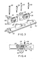
- Fig. 3 shows a projected exploded view of the mutual relationship between the idler wheel 28 and the flicker wheels 30 of Fig. 1.
- Each set of flicker wheels 30 and idler wheels 28 is mounted on adjacent pairs of mounting bosses 52 on the body 54 of the document stacker assembly 10.
- the respective flicker wheel 30 is mounted on a first mounting boss 52 and the respective idler wheel 28 held in its mounting yoke 50 is held on the mounting boss 52 next adjacent thereto.
- a first axle 56 holds the flicker wheel on its respective mounting boss 52 and a second axle 58 passes through the vertical joining section of the mounting yoke 50 of the spring-loaded idler wheel 28 to hold the idler wheel assembly 28, 50 on its respective mounting boss 52.
- the idler wheel 28 engages the centre portion of the flicker wheel 30.
- the flicker wheel 30 is waisted having a central waist portion 60 of a first diameter and top and bottom serrated portions 62 having a second diameter greater than the first diameter.
- the idler wheel 28 rotates, it does so at the linear velocity of the belt 16.
- the central waist portion 60 of the flicker wheel 30 will also rotate with a circumferential surface velocity equal to that of the belt 16.
- the serrated portions 62 of the flicker wheel 30 being of greater diameter than the waisted portion 60 will have a velocity at the ends of the tips of the projections thereon which is greater than the linear velocity of the belt 16.
- the first idler wheel compression spring 64 is shown in Fig. 1 advantageously employed in urging the bin wall member 36 against documents stored in bin 32.
- the bin wall member 36 is provided with a pivot 72 which allows it to be rotated against stored documents in the bin 32.
- the first idler wheel compression spring 64 presses against an extending arm 7 4 of each bin wall member 36 to urge it against the stored documents in the bin 32.
- the bin wall member 36 is urged clockwise as seen in Fig. 1 increasing the pressure on the first idler wheel compression spring 64 and thus urging the idler wheel 28 more forcefully against the belt 16 to increase frictional drive to documents as the bin 32 of each stacker assembly 12 becomes more full. This allows documents to be urged with more force into a bin already containing a number of documents than into a bin containing relatively few documents.
- the first idler wheel- compression spring 64 might equally well be braced against the body 54 of the document stacker assembly 10.
- Other forms of torque inducement to the yoke 50 are contemplated and are known in the art All that is required of them is that they urge the idler wheel 28 against the belt 16 in the manner shown.
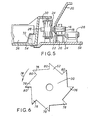
- Fig. 5 shows a vertical projected view of the apparatus of Fig. 1 viewed along the lines A-A' looking in the direction of the arrows.
- the elements of Fig. 5 are simply those previously described. In particular, attention is drawn to the manner in which the flicker wheel 30 is clearly waisted.
- the drive belt roller 18 may be driven by means of a motor mounted beneath the body 54 of the stacker assembly. Alternatively, the shaft of drive belt roller 18 may extend beneath the body 54 of the document stacker assembly 10 in turn to be belt driven to provide motive power for the belt 16.
- the drive belt roller 1 8 may equally be a simple idler roller merely mechanically supportive of the belt 16 which is otherwise driven by a different drive belt roller 18 elsewhere in the document stacker assembly 10.
- Fig. 6 shows a view from above the document flicker wheel 30, in particular showing the serrated portions 62.
- the serrated portions 62 which may equally be found on the lower edge of the flicker wheel 30 comprises projections 76.
- the flicker wheel assembly 30 rotates as indicated by the arrow 79.
- the projections 76 are of a serrasoidal shape with the sharper face 80 of each projection 76 substantially radial to the flicker wheel 30.
- the selected solenoid 26 is operated to extend its shaft 24 to move the selected document deflector 34 into the deflecting position.
- a document moving along the belt 16 encounters the upper and lower walls 38 of the document deflector 34 with their selected tapered shape, so it is deflected into the pinch between the waisted portion of the flicker wheel 30 and the idler wheel 28.
- the flicker wheel 30 by virtue of its being waisted imparts a vertical curvature to the document which lends it geometric strength.
- the document is driven as indicated by the arrow U up against the bin wall member 36 which provides resilient opposition thereto.
- the slight curvature imparted to the document by the waisted flicker wheel 30 can be employed through its mechanical strength imparted to the document to urge the document into an otherwise resistant stack of documents aready in a bin 32.
- the trailing edge of the document to be inserted into a bin 32 clears the pinch between the idler wheel 28 and the waisted portion 60 of the flicker wheel 30, so it is engaged by the sharper faces 80 of the projections 76 on the upper and lower portions 62 of the flicker wheel 30.
- the sharper faces 80 (or at least one of them) co-operate in the upper and lower serrated portions 62 of the flicker wheel 30 to urge the trailing edge of the document further into the bin 34 and to disengage therefrom at a predetermined position.
- Fig. 6 has shown the projections to be of a preferred serrasoidal configuration, it is to be appreciated that this same action can be achieved using projections of other shapes. It is simply necessary that the projections 76 may engage the trailing edge of a document as it leaves the pinch between the idler wheel 28 and the waisted portion 60 of the flicker wheel 30 and disengage therefrom when the document has reached a predetermined position. The action of the projections 76 is to change a movement vector from that indicated by the arrow V to that indicated by the arrow U.
- Fig. 7 shows a second variation on the manner in which the idler wheel 28 and the flicker wheel 30 can be mounted.
- the idler wheel 28' is mounted upon a modified yoke 82 which instead of being pivoted about its own axle 58 as shown in Fig. 3, is pivoted instead about the first axle 56 by means of long extending arms. Everything is as before, save for the omission of the second axle 58 and modification to the mounting bosses 52 into a single modified boss.
- Fig. 8 shows the urging of the idler wheel 28 against the belt 16 and flicker wheel 30 is once again achieved by the first idler wheel compression spring 64 which is placed on a modified spring projection 86 serving much the same purpose as the spring projection 66 shown in Fig. 4.
- the fractional mechanical advantage afforded the first idler wheel compression spring 64 in Fig. 4 by virtue of the radius ratios between the second axle 58 and the spring projection 66 and the second axle 58 and the point of contact of the idler wheel 28 with the belt 16 is improved from the very high ratio shown in Fig. 4 to a much lower ratio shown in Fig. 8 where the first idler wheel compression spring 64 is working at a mechanical advantage of around 0.5.
- the elastic restitution coefficient of the first idler wheel compression spring 64 may thus be reduced if the configuration of Figs. 7, 8 and 9 is adopted.
- Fig. 9 lastly shows a plan projection view corresponding in essence with that of Fig. 1 of the document stacker assembly 1 0 employing the idler wheel mounting method shown in Figs. 7 and 8.
- the first idler wheel compression springs urge the bin wall members 36 towards each bin 32, but this time with a controllably reduced force.
- the mechanical advantage (that is the position along the modified yoke 82) of the first idler wheel compression spring 64 can be selected to give both the desired force upon the bin wall member 36 and upon the idler wheel 28.
- All documents are thus aligned in the selected bin 32 with the trailing edges thereof in predetermined position.
- the documents are then ready to be removed therefrom to be placed as a feeder stack in a further document processing operation.
- a deflector 34 in a selected document stacker may be moved by its associated solenoid 26 and means provided in association with the bin wall member 36 whereby an individual document from the stack held in a bin 32 may once again be fed into the pinch between the flicker wheel 30 and the idler wheel 28.
- the documents may then be ducted back along the document path 14 in its reverse direction to that which it originally entered the document stacker assembly 10 for further processing elsewhere in the document encoding equipment.
- the serrated portions 62 of the flicker wheel 30 are shown in Figs. 1, 2 and 9 as projecting through the vertical wall 46 of the deflector 34. Whilst it is preferred that the projections 76 do not engage any document travelling along the document path. 14 by virtue of the clearance of the flicker wheel 30 from the belt 16, the selection of the shape of the projections 76 to be saw tooth and the rotation of the flicker wheel 30 in the direction selected for it means that a document proceeding along the document path 14, should it be unfortunate enough to encounter and engage a flicker wheel 30, will only encounter the shallow slope of the saw tooth, the sharper slope 80 of each saw tooth rotating away from the document. Thus the projections 76 of the flicker wheel 30 are made to present no impediment to a document travelling along the belt 16 in the event of the unexpected engagement therewith.
Landscapes
- Engineering & Computer Science (AREA)
- Mechanical Engineering (AREA)
- Pile Receivers (AREA)
- Delivering By Means Of Belts And Rollers (AREA)
- Separation, Sorting, Adjustment, Or Bending Of Sheets To Be Conveyed (AREA)
Applications Claiming Priority (2)
| Application Number | Priority Date | Filing Date | Title |
|---|---|---|---|
| GB8504739 | 1985-02-23 | ||
| GB08504739A GB2171396B (en) | 1985-02-23 | 1985-02-23 | Self-aligning document stacker |
Publications (3)
| Publication Number | Publication Date |
|---|---|
| EP0193267A2 true EP0193267A2 (fr) | 1986-09-03 |
| EP0193267A3 EP0193267A3 (en) | 1987-05-13 |
| EP0193267B1 EP0193267B1 (fr) | 1989-09-13 |
Family
ID=10575008
Family Applications (1)
| Application Number | Title | Priority Date | Filing Date |
|---|---|---|---|
| EP86300404A Expired EP0193267B1 (fr) | 1985-02-23 | 1986-01-21 | Dispositif d'empilage de documents à alignement automatique |
Country Status (5)
| Country | Link |
|---|---|
| US (1) | US4650178A (fr) |
| EP (1) | EP0193267B1 (fr) |
| JP (1) | JPH0829872B2 (fr) |
| DE (1) | DE3665561D1 (fr) |
| GB (1) | GB2171396B (fr) |
Cited By (6)
| Publication number | Priority date | Publication date | Assignee | Title |
|---|---|---|---|---|
| FR2593159A1 (fr) * | 1986-01-21 | 1987-07-24 | Gradco Systems Inc | Appareil recepteur de feuilles, notamment pour copieur. |
| EP0333067A3 (fr) * | 1988-03-12 | 1990-08-16 | Helmut Steinhilber | Appareil de triage pour feuilles de papier ou similaires |
| EP0449120A1 (fr) * | 1990-03-24 | 1991-10-02 | Canon Kabushiki Kaisha | Mécanisme de transport de feuilles |
| US5201518A (en) * | 1990-03-24 | 1993-04-13 | Canon Kabushiki Kaisha | Sheet transport mechanism having flapper |
| FR2706165A1 (fr) * | 1993-06-07 | 1994-12-16 | Gradco Japan Ltd | Appareil récepteur de feuilles à plateaux. |
| EP3421663A1 (fr) * | 2017-06-29 | 2019-01-02 | KBA-NotaSys SA | Procédé de traitement d'une bande de substrat dans des feuilles individuelles pour la production de documents de sécurité et installation pour sa mise en oeuvre |
Families Citing this family (9)
| Publication number | Priority date | Publication date | Assignee | Title |
|---|---|---|---|---|
| US4805894A (en) * | 1986-06-12 | 1989-02-21 | Transtechnology Corporation | Stacking methods and apparatus |
| US4819931A (en) * | 1986-09-09 | 1989-04-11 | Ikegami Tsushinki Co., Ltd. | Sorting apparatus |
| JPS63252871A (ja) * | 1987-04-10 | 1988-10-19 | Tanaka Seiki Kk | 紙葉類分類装置 |
| US5056940A (en) * | 1988-02-01 | 1991-10-15 | Kroy Inc. | Thermal printing device and tape supply cartridge therefor |
| US5261657A (en) * | 1991-03-19 | 1993-11-16 | Inter Innovation Ab | Document transport arrangement with relay-activated document gripping device including coacting relay armature return |
| US5396322A (en) * | 1993-11-05 | 1995-03-07 | Gradco (Japan) Ltd. | Single feed path dual sheet receiver |
| US5547184A (en) * | 1994-10-31 | 1996-08-20 | Bradco (Japan) Ltd. | Resilient sheet transport system |
| US6209865B1 (en) | 2000-01-10 | 2001-04-03 | Hewlett-Packard Company | Method and apparatus for improved stacking quality in a device that effects one or more of media to an output storage location |
| US6341771B1 (en) | 2000-01-25 | 2002-01-29 | The Goodyear Tire & Rubber Company | Method of stacking strips of flexible material |
Family Cites Families (16)
| Publication number | Priority date | Publication date | Assignee | Title |
|---|---|---|---|---|
| US3128093A (en) * | 1961-05-11 | 1964-04-07 | Universal Business Machines | Guideway for document sorting machines |
| US3472506A (en) * | 1967-08-23 | 1969-10-14 | Control Data Corp | Rotary diverter sorter |
| US3944207A (en) * | 1973-12-27 | 1976-03-16 | Xerox Corporation | Limitless sorter |
| JPS5139596U (fr) * | 1974-09-18 | 1976-03-24 | ||
| US3947018A (en) * | 1974-12-19 | 1976-03-30 | Xerox Corporation | Universal feeder-stacker |
| GB1548393A (en) * | 1975-04-28 | 1979-07-11 | Agfa Gevaert | Stack forming device |
| JPS5238837U (fr) * | 1975-09-11 | 1977-03-18 | ||
| JPS548503U (fr) * | 1977-06-17 | 1979-01-20 | ||
| JPS5552860A (en) * | 1978-10-06 | 1980-04-17 | Canon Inc | Distribution/accumulation apparatus for sheet material |
| FR2445182A1 (fr) * | 1978-12-28 | 1980-07-25 | Cii Honeywell Bull | Dispositif d'aiguillage de documents dans une machine comportant des moyens pour trier ces documents |
| JPS5911960Y2 (ja) * | 1979-03-07 | 1984-04-11 | 市光工業株式会社 | 丁合機 |
| JPS56165661A (en) * | 1980-05-27 | 1981-12-19 | Ricoh Co Ltd | Paper deviating device of book binder |
| US4520263A (en) * | 1980-10-21 | 1985-05-28 | Canon Kabushiki Kaisha | Collator with photoelectric bin fill detection |
| JPS57162091A (en) * | 1981-03-31 | 1982-10-05 | Anritsu Corp | Data processor |
| JPS5978064U (ja) * | 1982-11-18 | 1984-05-26 | 日立造船株式会社 | 研掃工具支持装置 |
| US4570918A (en) * | 1984-11-19 | 1986-02-18 | Xerox Corporation | Feeder and bottom stacker |
-
1985
- 1985-02-23 GB GB08504739A patent/GB2171396B/en not_active Expired
- 1985-08-12 US US06/764,458 patent/US4650178A/en not_active Expired - Fee Related
-
1986
- 1986-01-21 DE DE8686300404T patent/DE3665561D1/de not_active Expired
- 1986-01-21 EP EP86300404A patent/EP0193267B1/fr not_active Expired
- 1986-02-20 JP JP61037201A patent/JPH0829872B2/ja not_active Expired - Lifetime
Cited By (6)
| Publication number | Priority date | Publication date | Assignee | Title |
|---|---|---|---|---|
| FR2593159A1 (fr) * | 1986-01-21 | 1987-07-24 | Gradco Systems Inc | Appareil recepteur de feuilles, notamment pour copieur. |
| EP0333067A3 (fr) * | 1988-03-12 | 1990-08-16 | Helmut Steinhilber | Appareil de triage pour feuilles de papier ou similaires |
| EP0449120A1 (fr) * | 1990-03-24 | 1991-10-02 | Canon Kabushiki Kaisha | Mécanisme de transport de feuilles |
| US5201518A (en) * | 1990-03-24 | 1993-04-13 | Canon Kabushiki Kaisha | Sheet transport mechanism having flapper |
| FR2706165A1 (fr) * | 1993-06-07 | 1994-12-16 | Gradco Japan Ltd | Appareil récepteur de feuilles à plateaux. |
| EP3421663A1 (fr) * | 2017-06-29 | 2019-01-02 | KBA-NotaSys SA | Procédé de traitement d'une bande de substrat dans des feuilles individuelles pour la production de documents de sécurité et installation pour sa mise en oeuvre |
Also Published As
| Publication number | Publication date |
|---|---|
| GB2171396A (en) | 1986-08-28 |
| EP0193267A3 (en) | 1987-05-13 |
| JPS61197359A (ja) | 1986-09-01 |
| JPH0829872B2 (ja) | 1996-03-27 |
| US4650178A (en) | 1987-03-17 |
| DE3665561D1 (en) | 1989-10-19 |
| GB8504739D0 (en) | 1985-03-27 |
| EP0193267B1 (fr) | 1989-09-13 |
| GB2171396B (en) | 1988-11-23 |
Similar Documents
| Publication | Publication Date | Title |
|---|---|---|
| US4650178A (en) | Self-aligning document stacker | |
| US3162438A (en) | High speed sheet stacking system | |
| EP0037831B1 (fr) | Mecanismes d'entrainement pour les livrets de bancaires | |
| US5011129A (en) | Jam clearance apparatus for sheetfeeding device | |
| GB2142320A (en) | Vane-wheel paper sheet collecting apparatus | |
| US4029309A (en) | Set transport and stacker | |
| US5623722A (en) | Document set compiler and eject system | |
| AU684618B2 (en) | Banknote storage device | |
| US3087724A (en) | Document delivery and stacking apparatus | |
| US4273326A (en) | Collator | |
| US4155842A (en) | Document hold and view station for high speed item sorter apparatus | |
| US3861673A (en) | Bi-directional sheet transport | |
| US3046009A (en) | Device for conveying and stacking documents bearing registrations | |
| US3874650A (en) | Record separating, reading, and delivering apparatus | |
| US4106766A (en) | Sheet handling and stacking methods and apparatus | |
| US4046371A (en) | Document stacking device | |
| US3628787A (en) | Stacking device | |
| US5951008A (en) | Offsetting paper stackers | |
| GB2171395A (en) | Bidirectional document track | |
| US3503603A (en) | Friction feed device | |
| EP0030260B1 (fr) | Appareil transducteur d'information | |
| US3533620A (en) | Device for selecting and stacking documents such as punched cards | |
| JPS58116190A (ja) | 文書取扱装置 | |
| US3271026A (en) | Document stacking device | |
| CN221396272U (zh) | 纸张处理设备 |
Legal Events
| Date | Code | Title | Description |
|---|---|---|---|
| PUAI | Public reference made under article 153(3) epc to a published international application that has entered the european phase |
Free format text: ORIGINAL CODE: 0009012 |
|
| 17P | Request for examination filed |
Effective date: 19860129 |
|
| AK | Designated contracting states |
Kind code of ref document: A2 Designated state(s): BE DE FR IT NL SE |
|
| PUAL | Search report despatched |
Free format text: ORIGINAL CODE: 0009013 |
|
| AK | Designated contracting states |
Kind code of ref document: A3 Designated state(s): BE DE FR IT NL SE |
|
| RAP1 | Party data changed (applicant data changed or rights of an application transferred) |
Owner name: UNISYS CORPORATION |
|
| 17Q | First examination report despatched |
Effective date: 19880310 |
|
| GRAA | (expected) grant |
Free format text: ORIGINAL CODE: 0009210 |
|
| AK | Designated contracting states |
Kind code of ref document: B1 Designated state(s): BE DE FR IT NL SE |
|
| ET | Fr: translation filed | ||
| REF | Corresponds to: |
Ref document number: 3665561 Country of ref document: DE Date of ref document: 19891019 |
|
| ITF | It: translation for a ep patent filed | ||
| PLBE | No opposition filed within time limit |
Free format text: ORIGINAL CODE: 0009261 |
|
| STAA | Information on the status of an ep patent application or granted ep patent |
Free format text: STATUS: NO OPPOSITION FILED WITHIN TIME LIMIT |
|
| 26N | No opposition filed | ||
| PGFP | Annual fee paid to national office [announced via postgrant information from national office to epo] |
Ref country code: FR Payment date: 19911227 Year of fee payment: 7 |
|
| PGFP | Annual fee paid to national office [announced via postgrant information from national office to epo] |
Ref country code: SE Payment date: 19911230 Year of fee payment: 7 |
|
| PGFP | Annual fee paid to national office [announced via postgrant information from national office to epo] |
Ref country code: NL Payment date: 19920131 Year of fee payment: 7 |
|
| PGFP | Annual fee paid to national office [announced via postgrant information from national office to epo] |
Ref country code: BE Payment date: 19920207 Year of fee payment: 7 |
|
| PG25 | Lapsed in a contracting state [announced via postgrant information from national office to epo] |
Ref country code: SE Effective date: 19930122 |
|
| ITTA | It: last paid annual fee | ||
| PG25 | Lapsed in a contracting state [announced via postgrant information from national office to epo] |
Ref country code: BE Effective date: 19930131 |
|
| BERE | Be: lapsed |
Owner name: UNISYS CORP. Effective date: 19930131 |
|
| PG25 | Lapsed in a contracting state [announced via postgrant information from national office to epo] |
Ref country code: NL Effective date: 19930801 |
|
| NLV4 | Nl: lapsed or anulled due to non-payment of the annual fee | ||
| PG25 | Lapsed in a contracting state [announced via postgrant information from national office to epo] |
Ref country code: FR Effective date: 19930930 |
|
| REG | Reference to a national code |
Ref country code: FR Ref legal event code: ST |
|
| PGFP | Annual fee paid to national office [announced via postgrant information from national office to epo] |
Ref country code: DE Payment date: 19940127 Year of fee payment: 9 |
|
| EUG | Se: european patent has lapsed |
Ref document number: 86300404.0 Effective date: 19930810 |
|
| PG25 | Lapsed in a contracting state [announced via postgrant information from national office to epo] |
Ref country code: DE Effective date: 19951003 |
|
| PG25 | Lapsed in a contracting state [announced via postgrant information from national office to epo] |
Ref country code: IT Free format text: LAPSE BECAUSE OF NON-PAYMENT OF DUE FEES;WARNING: LAPSES OF ITALIAN PATENTS WITH EFFECTIVE DATE BEFORE 2007 MAY HAVE OCCURRED AT ANY TIME BEFORE 2007. THE CORRECT EFFECTIVE DATE MAY BE DIFFERENT FROM THE ONE RECORDED. Effective date: 20050121 |