EP0193275A2 - Elektrisches Lichtbogenschweisswerkzeug - Google Patents
Elektrisches Lichtbogenschweisswerkzeug Download PDFInfo
- Publication number
- EP0193275A2 EP0193275A2 EP86300553A EP86300553A EP0193275A2 EP 0193275 A2 EP0193275 A2 EP 0193275A2 EP 86300553 A EP86300553 A EP 86300553A EP 86300553 A EP86300553 A EP 86300553A EP 0193275 A2 EP0193275 A2 EP 0193275A2
- Authority
- EP
- European Patent Office
- Prior art keywords
- solenoid
- housing
- diode
- welding tool
- handle
- Prior art date
- Legal status (The legal status is an assumption and is not a legal conclusion. Google has not performed a legal analysis and makes no representation as to the accuracy of the status listed.)
- Withdrawn
Links
- 238000003466 welding Methods 0.000 title claims abstract description 30
- 238000010891 electric arc Methods 0.000 title abstract description 3
- 239000002184 metal Substances 0.000 claims abstract description 15
- 229910052751 metal Inorganic materials 0.000 claims abstract description 15
- 238000004804 winding Methods 0.000 claims abstract description 9
- 230000000717 retained effect Effects 0.000 claims description 5
- 239000000696 magnetic material Substances 0.000 claims description 2
- 239000000463 material Substances 0.000 claims description 2
- 150000002739 metals Chemical class 0.000 abstract description 4
- 238000010276 construction Methods 0.000 description 5
- XEEYBQQBJWHFJM-UHFFFAOYSA-N Iron Chemical group [Fe] XEEYBQQBJWHFJM-UHFFFAOYSA-N 0.000 description 4
- 239000000835 fiber Substances 0.000 description 3
- 230000003068 static effect Effects 0.000 description 3
- 230000000694 effects Effects 0.000 description 2
- 239000004033 plastic Substances 0.000 description 2
- 229920003023 plastic Polymers 0.000 description 2
- 229910000679 solder Inorganic materials 0.000 description 2
- 229910001369 Brass Inorganic materials 0.000 description 1
- 229910045601 alloy Inorganic materials 0.000 description 1
- 239000000956 alloy Substances 0.000 description 1
- 230000009286 beneficial effect Effects 0.000 description 1
- 239000010951 brass Substances 0.000 description 1
- 230000015556 catabolic process Effects 0.000 description 1
- 230000006378 damage Effects 0.000 description 1
- 230000004907 flux Effects 0.000 description 1
- 238000010438 heat treatment Methods 0.000 description 1
- 230000003993 interaction Effects 0.000 description 1
- 230000005389 magnetism Effects 0.000 description 1
- 238000004519 manufacturing process Methods 0.000 description 1
- 238000002844 melting Methods 0.000 description 1
- 230000008018 melting Effects 0.000 description 1
- 238000000034 method Methods 0.000 description 1
- 229910001220 stainless steel Inorganic materials 0.000 description 1
- 230000002459 sustained effect Effects 0.000 description 1
Images

Classifications
-
- B—PERFORMING OPERATIONS; TRANSPORTING
- B23—MACHINE TOOLS; METAL-WORKING NOT OTHERWISE PROVIDED FOR
- B23K—SOLDERING OR UNSOLDERING; WELDING; CLADDING OR PLATING BY SOLDERING OR WELDING; CUTTING BY APPLYING HEAT LOCALLY, e.g. FLAME CUTTING; WORKING BY LASER BEAM
- B23K9/00—Arc welding or cutting
- B23K9/24—Features related to electrodes
- B23K9/28—Supporting devices for electrodes
- B23K9/30—Vibrating holders for electrodes
-
- B—PERFORMING OPERATIONS; TRANSPORTING
- B23—MACHINE TOOLS; METAL-WORKING NOT OTHERWISE PROVIDED FOR
- B23K—SOLDERING OR UNSOLDERING; WELDING; CLADDING OR PLATING BY SOLDERING OR WELDING; CUTTING BY APPLYING HEAT LOCALLY, e.g. FLAME CUTTING; WORKING BY LASER BEAM
- B23K9/00—Arc welding or cutting
- B23K9/06—Arrangements or circuits for starting the arc, e.g. by generating ignition voltage, or for stabilising the arc
- B23K9/073—Stabilising the arc
- B23K9/0738—Stabilising of the arc by automatic re-ignition means
Definitions
- This invention relates to an improved electric arc welding tool, such as that described in G.B. 996126 which operates to strike an arc and maintain a succession of arcs to enable efficient welding operation to be performed . without a high degree of skill from an operator. In such a tool a sustained heavy current drain is avoided and the tool is suitable for use on low voltage supplies where difficulty would otherwise be experienced in rapidly striking and maintaining an arc.
- the known constructions of tool have an electro-magnetic means arranged to retract an electrode holder in opposition to a restoring means such as a spring,which urges the holder towards the workpiece, the solenoid means having an energising circuit which is completed through the electrode and workpiece by mutual contact of these whereby the electrode will be retracted to strike an arc and break the circuit, the restoring means returning the electrode to make contact with the workpiece, resulting in a succession of arcs between the electrode and workpiece.
- a restoring means such as a spring
- the electro-magnetic means is a solenoid having a core arranged to move and in electrical connection with the electrode holder; the core is in electrical contact throughout the whole of its movement with the electric current feed to the tool.
- the energising current for the solenoid is provided by a winding through which the current to the tool is fed. In such an arrangement it is difficult to arrive at the correct balance between coil winding and current. Welding thick metals requires high current with a coil of heavy gauge wire and few turns, whereas light gauge welding using low current needs a coil with a large number of turns and thinner gauge wire. The resulting tool to a large extent is therefore a compromise with the heavy wire wound tool unsuitable for light work and the thin wire wound tool unsuitable for heavy work. It was not possible hitherto to provide a single tool for the commonly used current range 15 to 150 Amps. GB 2108417A describes an improved construction of welding tool using an air gapped moving core.
- This invention seeks to provide a further improved construction for such a welding tool in which a wider range of currents can be used but with a single solenoid winding.
- an improvement in a welding tool having an electro-magnetic solenoid means arranged to retract an electrode holder in opposition to a restoring means which urges the holder towards the workpiece, the solenoid means having an energising circuit which is completed through the electrode and workpiece by mutual contact of these whereby the electrode will be retracted to strike an arc and break the circuit, the restoring means returning the electrode to make contact with the workpiece, wherein the solenoid includes a core of magnetic material with a first part fixed to the solenoid coil structure and a second part fixed to the electrode holder and movable with respect to the solenoid, the first and second parts being spaced longitudinally by an air gap, characterised in that a diode is included in series with the current feed from the said energising circuit. .
- the diode results in a considerably improved performance when welding thin materials and has the effect of reducing current fed from a transformer comprising the energising source. In most transformer supplies even though set to 30 amp range, the actual current is usually nearer 50 amps which may result in destruction of the metal weld.
- the diode does not simply act to reduce current it has been found that there is an unexpected interaction with the air-gap solenoid arrangement and it is believed that the natural vibration period of the moving core in conjunction with the half-wave supply produces the surprising and beneficial welding effect.
- the enhancement is not noticed with a conventional weld head nor with a head such as disclosed in GB 996126.
- the discovery in the present invention resides in the combination of weld head solenoid having an air eap and diode arrangement.
- the air gap is preferably positioned within the solenoid structure and with this arrangement the fixed core part ensures adequate magnetic flux when low currents are used to provide sufficient attraction.
- the second core part may be electrically connected with the energising circuit through a Flexible electric connection, which is secured without using soldered joints, e.g. by clamping or welding, and preferably the second core part has an extension passing through the solenoid core and secured to one end of the flexible electrical connection.
- the extension will advantageously pass, with clearance, through a boring in the first core part.
- the construction according to this invention enables the minimum number of turns to be used which reduces manufacturing costs and gives a lower coil resistance and hence less heating.
- the increased efficiency allows tools built to carry heavy currents to be usable and efficient at low currents when magnetism is weak.
- the solenoid will preferably be mounted on a weld head handle to form a tool.
- the base of the handle may be provided with a recess into which the diode is inserted and retained by a collar or abutment secured to the handle wall.
- One pole of the diode electrically contacts the handle which may be of metal, e.g. diecast alloy, the other pole is constituted by a leadout which connects at a terminal with the feed cable.
- the terminal being elecrically insulated from the handle with a switch, such as a shorting screw, provided to by-pass the diode.
- the handle thus serves as a mount providing protection for the diode and heat sinking properties.
- the diode should have forward current capability in excess of the max current surge and a reverse breakdown characteristic to take into acount any inductively induced spikes which may occur.
- the metal handle of the tool is enclosed in a rubber or plastics hand-grip.
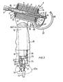
- the tool has a solenoid structure S which comprises a body 1 wound with a coil of wire 2 about a central hollow core 3.
- the core contains a first fixed iron core part 4 and a second movable iron core part 5.
- the core part 5 has a threaded brass studding 6 connected thereto and which passes with clearance through a boring in the core part 4 to connect with conducting leaves 7 serving as a mechanically flexible electric current feed to the welding tool holder 8 via the studding 6 and core part 5.
- the studding is adjustable by means of a nut 13 and provides an air gap 9 between the two iron core parts. By this means magnetic attraction is increased at lower weld currents.
- the tool holder 8 and core part 5 are normally urged away from the core part 4 by a return spring 10 and the tension in this spring will be increased when the studding 6 is adjusted by nut 13 to close the gap 9.
- the leaves 7 are secured to the studding by lock nuts 14 and to the body 1 by clamp means such as a rivet or solder or welding 15.
- the rivet or solder or like joint 15 electrically connects the leaves 7 with one end of the solenoid coil 2 by a metal plate 16 insulated from the coil body by a fibre washer 17.
- the other end of the coil 2 connects with a diecast housing 18 contiguous with a tubular handle 19.
- the other end of the solenoid has an insulating fibre washer 20 and plate 23 and the assembly including core 3 is retained by press-fitted diaphragm spring clips 21,22
- the tool may be arranged as a self-striking, arc-restoring static electrode holder. If a weak return spring 10 is used, then welding current passing through the coil will hold the two iron cores 4 and 5 together solidly. In this form the role is as a static electrode holder. Should the arc break the electrode will move forward to make electrical contact and then draw away thus restoring the arc.
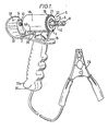
- FIGS 1 and 2 show the general construction which comprises a single die-cast body comprising a hollow cylindrical head housing 18 and integral cylindrical handle 19.
- the solenoid body is retained in the head 18 by the fibre washers 17,20, metal plates 16,23 and spring clip washers 21,22 also serving to trap the core 3 and hold same in position.
- One end of the solenoid winding connects at 15 with the leaves 7, the other end of the winding connects to body 18, 19, by clamping between two lugs 39 forced together by rivet or screw means 40.
- the base of the handle 19 is bored at 24 and has shoulder 25.
- a diode 26 of "top-hat” shape is received in the bore and the rim 27 thereof bears-on shoulder 25 and is clamped by an insert 28 retained by rivet 29.
- An insulating plate 30 is also clamped by the rivet 29 and this plate carries a terminal block 31 to which the current feed cable 32 is bonded, along with lead in 33 to diode 26.
- a screw 34 may be adjusted to bridge the diode if same is not required in circuit.
- the electrical circuit is thus:- from a transformer supply (not shown) through cable 32 to terminal 31 thence via lead 33 through the diode 26 to the casing thereof which is in electrical connection with handle 19. Current passes then to housing 18 through the solenoid winding 2 to connection 15 via leaves 7, studding 6, core part 5 and tool-holder 8 via the weld rod (not shown) to the workpiece which is electrically connected to the other side of the transformer.
- the cable 32 preferably has a clip 36 at the remote end to connect with the transformer.
- the handle 19 is provided with a rubber hand grip 35 slid thereover.
- the combination of air-gapped moving core solenoid and the series diode provides a low current welding capability which hitherto has been impossible to achieve, there normally being insufficient current to maintain an arc or if the current is sufficient the arc cannot be controlled to provide a weld without the well known problem of melting a hole in the workpiece.
- a rigid plastic guard 37 also serves as a stand wherein the part 38 thereof may rest on a surface together with heel 35a of the handle.
Landscapes
- Engineering & Computer Science (AREA)
- Physics & Mathematics (AREA)
- Plasma & Fusion (AREA)
- Mechanical Engineering (AREA)
- Arc Welding Control (AREA)
Applications Claiming Priority (2)
| Application Number | Priority Date | Filing Date | Title |
|---|---|---|---|
| GB858502192A GB8502192D0 (en) | 1985-01-29 | 1985-01-29 | Arc welding tool |
| GB8502192 | 1985-01-29 |
Publications (2)
| Publication Number | Publication Date |
|---|---|
| EP0193275A2 true EP0193275A2 (de) | 1986-09-03 |
| EP0193275A3 EP0193275A3 (de) | 1987-09-30 |
Family
ID=10573578
Family Applications (1)
| Application Number | Title | Priority Date | Filing Date |
|---|---|---|---|
| EP86300553A Withdrawn EP0193275A3 (de) | 1985-01-29 | 1986-01-28 | Elektrisches Lichtbogenschweisswerkzeug |
Country Status (3)
| Country | Link |
|---|---|
| US (1) | US4614857A (de) |
| EP (1) | EP0193275A3 (de) |
| GB (2) | GB8502192D0 (de) |
Families Citing this family (7)
| Publication number | Priority date | Publication date | Assignee | Title |
|---|---|---|---|---|
| US5079405A (en) * | 1990-11-29 | 1992-01-07 | Charles W. Pierce | Electrode oscillating mechanism for welding electrode holder |
| US7358458B2 (en) * | 2005-01-25 | 2008-04-15 | Lincoln Global, Inc. | Methods and apparatus for tactile communication in an arc processing system |
| US10391579B2 (en) * | 2013-03-15 | 2019-08-27 | Huys Industries Limited | Ventilated vibrating electrode holder |
| US10391574B2 (en) | 2013-12-16 | 2019-08-27 | Huys Industries Limited | Welding method and apparatus therefor |
| RU2682553C1 (ru) * | 2018-04-12 | 2019-03-19 | Федеральное государственное бюджетное учреждение науки Институт физики твердого тела Российской академии наук (ИФТТ РАН) | Электрод для дуговой плавки металлов |
| US12409504B2 (en) | 2019-02-05 | 2025-09-09 | Huys Industries Limited | Welding applicator and method of application |
| WO2021207838A1 (en) | 2020-04-14 | 2021-10-21 | Huys Industries Limited | Welded assembly and method of welding using electro-spark discharge |
Family Cites Families (11)
| Publication number | Priority date | Publication date | Assignee | Title |
|---|---|---|---|---|
| US3089946A (en) * | 1961-05-08 | 1963-05-14 | Deweld Inc | Stud welder |
| DE1540965C3 (de) * | 1965-10-28 | 1975-01-02 | Messer Griesheim Gmbh, 6000 Frankfurt | Einrichtung zum WechselstromlichtbogenschwelBen von Leichtmetallen |
| US3496325A (en) * | 1966-06-03 | 1970-02-17 | Trw Inc | Apparatus and circuitry for welding studs |
| US3526741A (en) * | 1966-12-07 | 1970-09-01 | Trw Inc | Method and apparatus for welding studs |
| BE809746A (fr) * | 1974-01-15 | 1974-05-02 | Alimentation en courants electriques (continu et alternatif) d'installations de plasmas a hautes temperatures. | |
| GB1470769A (en) * | 1974-06-25 | 1977-04-21 | Royston A | Soldering tools |
| US4178495A (en) * | 1976-01-12 | 1979-12-11 | Trw, Inc. | Apparatus for welding studs to workpieces |
| GB1491076A (en) * | 1976-03-11 | 1977-11-09 | Hirschmann F | Arc welding equipment |
| GB1601589A (en) * | 1977-09-06 | 1981-11-04 | Migatronic Svejsemask | Arc welding apparatus |
| GB2108417A (en) * | 1981-10-27 | 1983-05-18 | Roy Neville | Arc welding apparatus |
| SU1359087A1 (ru) * | 1982-03-03 | 1987-12-15 | Цника (Инопредприятие) | Устройство дл получени импульсного сварочного тока (его варианты) |
-
1985
- 1985-01-29 GB GB858502192A patent/GB8502192D0/en active Pending
- 1985-02-08 US US06/699,471 patent/US4614857A/en not_active Expired - Fee Related
-
1986
- 1986-01-28 GB GB08601996A patent/GB2170134A/en not_active Withdrawn
- 1986-01-28 EP EP86300553A patent/EP0193275A3/de not_active Withdrawn
Also Published As
| Publication number | Publication date |
|---|---|
| GB8502192D0 (en) | 1985-02-27 |
| US4614857A (en) | 1986-09-30 |
| GB8601996D0 (en) | 1986-03-05 |
| GB2170134A (en) | 1986-07-30 |
| EP0193275A3 (de) | 1987-09-30 |
Similar Documents
| Publication | Publication Date | Title |
|---|---|---|
| CA2088038C (en) | Electromagnetic pickup tool | |
| US4614857A (en) | Solenoid energizing circuit for an electric arc welding tool | |
| EP0981146A1 (de) | Solenoidstruktur für hohe Stromstärken | |
| US20080110867A1 (en) | Stud retaining weld head | |
| US1810212A (en) | Electric tool | |
| US3610877A (en) | Flexible electrode structure | |
| US2692935A (en) | Soldering tool | |
| US2542629A (en) | Electric heating apparatus | |
| US3219793A (en) | Sectional welding electrode holder | |
| US3172992A (en) | Air cooled arc welding nozzle assembly | |
| US1709716A (en) | Welding clamp | |
| US2572084A (en) | Welding electrode holder construction | |
| US2437633A (en) | Electric welding ground | |
| US4040714A (en) | C-clamp ground adapters | |
| GB2223919A (en) | Welding apparatus | |
| US2874264A (en) | Percussion welding gun for welding wires to articles | |
| US2465879A (en) | Portable spot welder | |
| JP2839290B2 (ja) | 抵抗溶接機の溶接ヘッド装置 | |
| US2401383A (en) | Electrode holder | |
| RU907U1 (ru) | Плазмотрон | |
| AU2005100632A4 (en) | Improvements to Magnetic Earthing Clamps | |
| US507419A (en) | Electric heating and welding apparatus | |
| US2495044A (en) | Electric soldering device for commutators | |
| US2057320A (en) | Electric welding tool | |
| US2966577A (en) | Arc welding torch |
Legal Events
| Date | Code | Title | Description |
|---|---|---|---|
| PUAI | Public reference made under article 153(3) epc to a published international application that has entered the european phase |
Free format text: ORIGINAL CODE: 0009012 |
|
| AK | Designated contracting states |
Kind code of ref document: A2 Designated state(s): AT BE CH DE FR IT LI LU NL SE |
|
| PUAL | Search report despatched |
Free format text: ORIGINAL CODE: 0009013 |
|
| AK | Designated contracting states |
Kind code of ref document: A3 Designated state(s): AT BE CH DE FR IT LI LU NL SE |
|
| 17P | Request for examination filed |
Effective date: 19880321 |
|
| 17Q | First examination report despatched |
Effective date: 19881128 |
|
| STAA | Information on the status of an ep patent application or granted ep patent |
Free format text: STATUS: THE APPLICATION IS DEEMED TO BE WITHDRAWN |
|
| 18D | Application deemed to be withdrawn |
Effective date: 19910801 |