EP0193323A2 - Filteranlage - Google Patents
Filteranlage Download PDFInfo
- Publication number
- EP0193323A2 EP0193323A2 EP86301063A EP86301063A EP0193323A2 EP 0193323 A2 EP0193323 A2 EP 0193323A2 EP 86301063 A EP86301063 A EP 86301063A EP 86301063 A EP86301063 A EP 86301063A EP 0193323 A2 EP0193323 A2 EP 0193323A2
- Authority
- EP
- European Patent Office
- Prior art keywords
- cloth
- filter
- drive
- motor
- filter cloth
- Prior art date
- Legal status (The legal status is an assumption and is not a legal conclusion. Google has not performed a legal analysis and makes no representation as to the accuracy of the status listed.)
- Granted
Links
Images


Classifications
-
- B—PERFORMING OPERATIONS; TRANSPORTING
- B01—PHYSICAL OR CHEMICAL PROCESSES OR APPARATUS IN GENERAL
- B01D—SEPARATION
- B01D29/00—Filters with filtering elements stationary during filtration, e.g. pressure or suction filters, not covered by groups B01D24/00 - B01D27/00; Filtering elements therefor
- B01D29/09—Filters with filtering elements stationary during filtration, e.g. pressure or suction filters, not covered by groups B01D24/00 - B01D27/00; Filtering elements therefor with filtering bands, e.g. movable between filtering operations
-
- B—PERFORMING OPERATIONS; TRANSPORTING
- B01—PHYSICAL OR CHEMICAL PROCESSES OR APPARATUS IN GENERAL
- B01D—SEPARATION
- B01D29/00—Filters with filtering elements stationary during filtration, e.g. pressure or suction filters, not covered by groups B01D24/00 - B01D27/00; Filtering elements therefor
- B01D29/60—Filters with filtering elements stationary during filtration, e.g. pressure or suction filters, not covered by groups B01D24/00 - B01D27/00; Filtering elements therefor integrally combined with devices for controlling the filtration
-
- B—PERFORMING OPERATIONS; TRANSPORTING
- B01—PHYSICAL OR CHEMICAL PROCESSES OR APPARATUS IN GENERAL
- B01D—SEPARATION
- B01D29/00—Filters with filtering elements stationary during filtration, e.g. pressure or suction filters, not covered by groups B01D24/00 - B01D27/00; Filtering elements therefor
- B01D29/60—Filters with filtering elements stationary during filtration, e.g. pressure or suction filters, not covered by groups B01D24/00 - B01D27/00; Filtering elements therefor integrally combined with devices for controlling the filtration
- B01D29/605—Filters with filtering elements stationary during filtration, e.g. pressure or suction filters, not covered by groups B01D24/00 - B01D27/00; Filtering elements therefor integrally combined with devices for controlling the filtration by level measuring
-
- B—PERFORMING OPERATIONS; TRANSPORTING
- B01—PHYSICAL OR CHEMICAL PROCESSES OR APPARATUS IN GENERAL
- B01D—SEPARATION
- B01D29/00—Filters with filtering elements stationary during filtration, e.g. pressure or suction filters, not covered by groups B01D24/00 - B01D27/00; Filtering elements therefor
- B01D29/76—Handling the filter cake in the filter for purposes other than for regenerating
- B01D29/78—Handling the filter cake in the filter for purposes other than for regenerating for washing
Definitions
- This invention relates to filtering equipment, and more particularly to the filtering of liquid-based slurries.
- Conventional filtration equipment for this purpose commonly takes the form of an endless filter cloth which is transported over one or more suction boxes, whereby slurry applied to the upper surface of the filter cloth is "dewatered" by the action of the vacuum in the suction box drawing the liquid through the cloth, leaving the filter cake to be carried onward by the cloth to a suitable discharge point.
- To move the filter cloth while suction is taking place is usually difficult or can result in an unacceptably high rate of wear of the cloth, and accordingly the cloth is normally moved intermittently, with suction taking place while the cloth is stationary.
- the intermittent movement of the cloth may be achieved by reciprocating part of the support for the filter cloth, for example one of the rollers around which the cloth is trained, while arranging for the movement of the cloth to be unidirectional, so that the reciprocating movement of the cloth-supporting member advances the cloth during its movement in one direction, while the unidirectional mechanism prevents reverse movement of the cloth when the cloth-supporting member is moved in the other direction.
- the reciprocating movement is commonly achieved by means of a hydraulic or pneumatic ram, and the cloth is advanced by a fixed increment on each stroke of the ram. Examples of such a mechanism can be seen from GB 1434211, GB 2052290, GB 2090764 and GB 2119669.
- Such a method for intermittently advancing the filter cloth is mechanically simple, but is limited in its range of operating options, since the length of the incremental advance is fixed by the stroke of the ram, and the speed of advance is difficult to control, either overall or during the course of each advancing stroke.
- a further problem, in part associated with the foregoing constructions, is that of cracking of the filter cake as a result of the intermittent movement of the filter cloth, since the cloth cannot be totally inextensible. If cracks are formed in the filter cake, then when the cake is washed, the wash liquid will preferentially flow through the cracks rather than through the cake, resulting in inefficient washing. Likewise drying of the cake by drawing air through it will be inefficient if there are cracks.
- the filter equipment comprises a frame 10 on which an endless filter cloth 12 is carried and guided by a variety of rollers journalled to the frame.
- rollers comprise a driven end return roller 14 at one end of the frame, and a free running end return roller 16 at the other end of the frame, with free running guide rollers 18,20,22,24,26,28 along the lower (return) run of the filter cloth.
- the roller 20 is a tracking roller to provide lateral control
- the roller 22 is a gravity tensioning roller.
- a dam roller 30 bears down upon the top surface of the filter cloth on the top (filtering) run of the cloth, at the beginning of the run: the cloth being driven in the direction indicated by the arrow X by means of a motor 32 connected to the roller 14. (Instead of driving the roller 14, the motor may be arranged to drive a roller at some other point in the cloth circuit.
- the filter cloth lies in a filter trough 34 which has a compartmented suction box 35, the compartments having respective filtrate outlets 36, 38,40,42 leading to respective filtrate receiving containers 44,46,48,50, which in turn are drained, for example by means of respective filtrate pumps 52,54,56,58 (for the sake of clarity, only one connection between filtrate pump and filtrate container is shown in Fig. 1; namely between container 12 and pump 54: however, the connection is the same in relation to the other containers also).
- the drainage could be by gravity.
- Vacuum is applied to the filter containers 44 to 50 by means of a common vacuum manifold 60 operated by a vacuum pump 62 driven by a motor 64.
- a vacuum pump 62 driven by a motor 64.
- different levels of vacuum in various compartments could be provided by separate vacuum pumps connected to different containers or groups of containers.
- the connection between the filtrate outlets 36 to 42 and their respective filtrate containers 44 to 50 is made via respective motorised shut-off valves 66 (for clarity, only one such is shown in Fig. 1).
- a vacuum tray assembly 68 In the base of the trough 34 above the suction box 35 is located a vacuum tray assembly 68, whose top surface is formed with a series of transverse channels 70 to apply vacuum to the undersurface of the filter cloth 12, and receive filtrate therefrom, each channel having a central drain opening 72 leading to one of the filtrate outlets 36 to 42.
- various conventional devices such as a slurry feed assembly 74, flap dam assemblies 76 and cake wash distribution assemblies 78.
- the number of compartments in the suction box, and the number of filtrate receiving containers and pumps can be varied as required by the particular filtering application, even so far as having only a single compartment, container and pump.
- FIG. 3 shows the working of the apparatus of Figs. 1 and 2, but would vary according to the particular apparatus or filter application under consideration. Movement of the filter cloth is detected by means of a device for measuring the rotation of one of the idler rollers for the filter cloth.
- a device 80 is shown connected to the roller 18, but it could be connected to any of the other idler rollers (in Fig. 3 not all the rollers shown in Fig. 1 are represented).
- the rotation can be measured by any suitable means, but one suitable device is an optical incremental shaft encoder (Logicon Systems Limited W-Series type W9D43 10/1), which provides a digital pulse electrical output, which is fed to a programmable controller 82 (Mitsubishi F-20PE).
- the motor 32 is an electric induction motor with integral gearbox (Allspeeds Limited MAS Series 35/D) driving the roller 14 through a pulley belt (not shown).
- the motor speed is controlled by an inverter 84 (Allspeeds Limited Toshiba Tosvert-130G-4030) in response to signals from the controller 82.
- the controller also controls the operation of the various valves V l to Vg shown in Fig. 3, and also referred to in Fig. 4.
- the four valves V 1 shown in Fig. 3 correspond to the valves 66 controlling the application of vacuum from the filtrate containers 44 to 50 to the outlets 36 to 42 respectively from the suction box 35.
- valve V 2 linked to the vacuum box (by junctions 37 in the conduits connecting the vacuum box to the valves 66 - see Fig. 2). Operation of this valve releases the vacuum in the suction box, but, being upstream of the valves 66 and operable only when the valves 66 are closed, vacuum is maintained in the filtrate containers 44 to 50.
- Valve V 3 is optionally provided in a line supplying liquid for washing the filter cloth in the return run.
- Valve V 4 is provided in an optional air line which supplies air to pressurise the suction box and provide a lift to the filter cloth over the vacuum tray, thereby facilitating its forward travel.
- Optional valve V 6 is in a line connecting a cloth drying roller 26 to filtrate container 50, so as to draw off liquid from the filter cloth during its return run.
- Valve V 7 lines in the supply line to the slurry feed 74, while valves V 8 and V g line in the supply lines to the product wash distributors 78.
- Further items of the equipment include a tracking sensor TS which checks the correct tracking of the cloth, and level sensors LS which control the withdrawal of liquid in the containers 44 to 50, for example by switching on pumps 52 to 58, when the liquid level rises to a predetermined level.
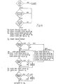
- the controller 82 can be programmed in a number of different ways, according to the intended operation of the filter equipment, but one such programme is illustrated with reference to Fig. 4. Inspection of this programme will show that it provides three alternative modes of operation, designated A, B and C respectively.
- the procedure for operating the equipment is:
- the controller goes through steps to to t 3 , which are common to all three modes of operation. This involves closing the valves V 1 (66) so that vacuum is cut off from the vacuum box: opening vacuum vent valve V 2 so that the vacuum box can rise to atmospheric pressure: opening the cloth wash valve V 3 so that washing liquid is applied to the return run of the cloth during the cloth advance which is about to take place: opening cloth lift air valve V 4 , pressurising the vacuum box and giving a lift to the filter cloth: opening the cloth drying valve V 6 (if provided): and then starting the drive motor 32. This initiates advance of the filter cloth, which is measured by the encoder device 80, so that the controller can shut off the motor when the cloth has moved forward a predetermined increment.
- sub-routine l which involves opening the feed valve V 7 to supply slurry to the filter cloth, opening the cake wash valves 8 and 9; and subsequently closing the cake wash valves and feed valve after a predetermined period (during the forward advance of the filter cloth).
- the controller stops the drive motor at point t 4 in the program when the encoder 18 indicates that the cloth has moved forward the predetermined incremental distance.
- the controller closes the cloth wash valve V 3 , the cloth lift valve V 4 and the cloth drying valve V 6 (if provided).
- routine A the slurry and wash liquid are fed to the filter cloth while it is moving forward, but before any vacuum is applied to the cloth.
- routine B the controller ignores routine A, and between points t 3 and t 4 it merely moves the cloth forward the predetermined incremental distance. It then goes through sub-routine I between points t 5 and t 6 , so that the slurry and cake wash liquid are supplied to the filter cloth while the cloth is stationary but before any vacuum is applied to it.
- routine C If, instead, routine C has been selected, the programmer ignores routines A and B, and goes through sub-routine I between points t 7 and t 8 in the program; so that slurry and cake wash liquid are applied to the filter cloth when the cloth is stationary and vacuum is being applied to the cloth.
- a feature of the inverter 84 is that it has a programmable ramp facility, which provides a controlled and predetermined increase and decrease in the output to the motor when switching on and switching off respectively.
- the motor is provided with controlled acceleration and deceleration, which can be selected so as to minimise shock applied to the filter cloth, and hence to the filter cake, and thereby reduce the risk of cracking of the filter cake.
- Another feature of the equipment is that the extent of incremental advance of the filter cloth can be varied as desired simply by programming the controller 82 accordingly.
- the stationary period can even be eliminated altogether, so that the cloth runs continuously, which may be practicable in certain applications where only a very light slurry is being filtered.
- the ability to vary the increment at will makes the equipment extremely versatile, so that it can be used in a wide variety of applications.
- by determining the incremental advance by measuring the rotation of an idler roller in contact with the cloth, the forward movement of the cloth can be accurately determined.
- the incremental movement is determined by a fixed time increment, or by measurement of the rotation of the driving system for the filter cloth, the distance moved by the cloth is much less accurately known, because of the possible slippage between the cloth and the drive roller 14.
Landscapes
- Chemical & Material Sciences (AREA)
- Chemical Kinetics & Catalysis (AREA)
- Filtration Of Liquid (AREA)
- Separation By Low-Temperature Treatments (AREA)
- Centrifugal Separators (AREA)
- Glass Compositions (AREA)
- Oscillators With Electromechanical Resonators (AREA)
Priority Applications (1)
| Application Number | Priority Date | Filing Date | Title |
|---|---|---|---|
| AT86301063T ATE48380T1 (de) | 1985-02-19 | 1986-02-17 | Filteranlage. |
Applications Claiming Priority (2)
| Application Number | Priority Date | Filing Date | Title |
|---|---|---|---|
| GB858504177A GB8504177D0 (en) | 1985-02-19 | 1985-02-19 | Filtering equipment |
| GB8504177 | 1985-02-19 |
Publications (3)
| Publication Number | Publication Date |
|---|---|
| EP0193323A2 true EP0193323A2 (de) | 1986-09-03 |
| EP0193323A3 EP0193323A3 (en) | 1986-12-30 |
| EP0193323B1 EP0193323B1 (de) | 1989-12-06 |
Family
ID=10574683
Family Applications (1)
| Application Number | Title | Priority Date | Filing Date |
|---|---|---|---|
| EP86301063A Expired EP0193323B1 (de) | 1985-02-19 | 1986-02-17 | Filteranlage |
Country Status (6)
| Country | Link |
|---|---|
| US (1) | US4851113A (de) |
| EP (1) | EP0193323B1 (de) |
| AT (1) | ATE48380T1 (de) |
| AU (2) | AU594663B2 (de) |
| DE (1) | DE3667247D1 (de) |
| GB (2) | GB8504177D0 (de) |
Families Citing this family (6)
| Publication number | Priority date | Publication date | Assignee | Title |
|---|---|---|---|---|
| GB2232611B (en) * | 1989-06-02 | 1992-10-14 | D & C Ltd | Horizontal belt vacuum filtration apparatus |
| FR2660942B1 (fr) * | 1990-04-11 | 1994-09-09 | Kaysersberg Sa | Procede d'impregnation en continu d'une nappe textile. |
| ATE128038T1 (de) * | 1991-06-13 | 1995-10-15 | Tsukishima Kikai Co | Vorrichtung zur vakuumfiltration mit horzontalem bandfilter. |
| DE4139324C1 (en) * | 1991-11-29 | 1992-09-24 | Mercedes-Benz Aktiengesellschaft, 7000 Stuttgart, De | Filter plant where belt movement is independently controlled of slippage etc. - has filter box above belt, and suction box to receive filtrate passing through stationary belt, and markings to check belt movement |
| US5957759A (en) * | 1997-04-17 | 1999-09-28 | Advanced Micro Devices, Inc. | Slurry distribution system that continuously circulates slurry through a distribution loop |
| US5934978A (en) * | 1997-08-15 | 1999-08-10 | Advanced Micro Devices, Inc. | Methods of making and using a chemical-mechanical polishing slurry that reduces wafer defects |
Family Cites Families (14)
| Publication number | Priority date | Publication date | Assignee | Title |
|---|---|---|---|---|
| US2445416A (en) * | 1945-02-22 | 1948-07-20 | Westinghouse Electric Corp | Control system for paper machine drives |
| US2895614A (en) * | 1955-12-12 | 1959-07-21 | Komline Sanderson Eng Corp | Filtering unit |
| GB846855A (en) * | 1959-05-13 | 1960-08-31 | Komline Sanderson Eng Corp | Improvements in filtering units |
| US3310172A (en) * | 1963-02-28 | 1967-03-21 | Manitowoc Engineering Corp | Apparatus for filtering liquid |
| US3464557A (en) * | 1966-12-12 | 1969-09-02 | Bowser Inc | Movable filter and magnetic sealing means |
| FR1509336A (fr) * | 1966-12-24 | 1968-01-12 | Hydromation Engineering Compan | Appareil et procédé pour filtrer les liquides pollués |
| US3506128A (en) * | 1967-03-28 | 1970-04-14 | Ajem Lab Inc | Filter apparatus |
| GB1434211A (en) * | 1973-01-09 | 1976-05-05 | Pierson H G W | Horizontal belt filters |
| US4233157A (en) * | 1977-11-23 | 1980-11-11 | Miller Peter A | Travelling sheet, flat-bed filter apparatus and system |
| DE2803287A1 (de) * | 1978-01-26 | 1979-08-02 | Alfred Dipl Ing Krumpe | Steuerungsprinzip zum optimalen einstellen des sanftauslaufes eines drehstrom-asynchronmotors |
| US4159247A (en) * | 1978-08-07 | 1979-06-26 | Amsted Industries Incorporated | Locking filter apparatus and method |
| DE2924277C2 (de) * | 1979-06-15 | 1987-05-07 | BHS-Bayerische Berg-, Hütten- und Salzwerke AG, 8000 München | Filterverfahren und Bandfilter zu seiner Durchführung |
| GB2090764B (en) * | 1981-01-10 | 1984-08-22 | Pierson Henri G W | Horizontal vacuum belt filter |
| GB2119669B (en) * | 1982-05-05 | 1985-10-16 | Pierson Research Trust The Mar | Endless belt filter |
-
1985
- 1985-02-19 GB GB858504177A patent/GB8504177D0/en active Pending
-
1986
- 1986-02-17 GB GB8603898A patent/GB2171025B/en not_active Expired
- 1986-02-17 AT AT86301063T patent/ATE48380T1/de not_active IP Right Cessation
- 1986-02-17 DE DE8686301063T patent/DE3667247D1/de not_active Expired - Lifetime
- 1986-02-17 EP EP86301063A patent/EP0193323B1/de not_active Expired
- 1986-02-18 AU AU53682/86A patent/AU594663B2/en not_active Expired
-
1987
- 1987-09-18 US US07/098,460 patent/US4851113A/en not_active Expired - Lifetime
-
1989
- 1989-09-06 AU AU41146/89A patent/AU612511B2/en not_active Expired
Also Published As
| Publication number | Publication date |
|---|---|
| GB2171025B (en) | 1989-09-13 |
| GB8603898D0 (en) | 1986-03-26 |
| EP0193323A3 (en) | 1986-12-30 |
| EP0193323B1 (de) | 1989-12-06 |
| AU612511B2 (en) | 1991-07-11 |
| US4851113A (en) | 1989-07-25 |
| GB8504177D0 (en) | 1985-03-20 |
| GB2171025A (en) | 1986-08-20 |
| AU594663B2 (en) | 1990-03-15 |
| AU4114689A (en) | 1990-01-04 |
| ATE48380T1 (de) | 1989-12-15 |
| AU5368286A (en) | 1986-08-28 |
| DE3667247D1 (de) | 1990-01-11 |
Similar Documents
| Publication | Publication Date | Title |
|---|---|---|
| US5475965A (en) | Machine for sealing containers by applying a covering film | |
| EP0206985B1 (de) | Vorrichtung zum Vereinzeln von aneinander anliegenden Einzelstücken | |
| US2991753A (en) | Adhesive applying apparatus | |
| US4851113A (en) | Filter apparatus for slurry | |
| US4788786A (en) | Article transporting and raising and lowering apparatus | |
| US5887701A (en) | Method and unit for forming and conveying groups of products | |
| RU95109437A (ru) | Конвейерная ленточная система | |
| CN110155768A (zh) | 一种用于片状物料的分路传输装置 | |
| DE329830T1 (de) | Bahnspannungsvorrichtung. | |
| GB1576819A (en) | Method and device for removing a liquid for a mixture of liquid and solid substances | |
| US4180995A (en) | Pressing apparatus for squeezing laundry and the like | |
| GB2209128A (en) | Moving band filter | |
| JP3538455B2 (ja) | フイルタロッドを貯蔵部から空圧により移送が行われる導管内へ移送するための装置 | |
| DE3004894C2 (de) | Vorrichtung zum Schneiden von plastisch verformbaren Warenbahnen in Einzelabschnitte | |
| EP0274790B1 (de) | Vorrichtung für die Zuführung von Behältern zu einer Behandlungsanlage | |
| CN219928984U (zh) | 一种输送装置 | |
| EP0825118B1 (de) | Verfahren zum Bilden von Gruppen von Paketen | |
| US2997179A (en) | Sifting device and method for filtering with the aid of said sifting device | |
| US4869198A (en) | Vacuum debubbler machine | |
| US4614583A (en) | Horizontal belt filter with incremental belt advance | |
| CN212087829U (zh) | 饼干整理浇注撒料一体化生产装置 | |
| US3403622A (en) | Web printing machines | |
| CN210312472U (zh) | 一种传送硅片水道线用机械手 | |
| CN1157349A (zh) | 具有移动槽和固定端站的特别用于纺织品的处理机 | |
| EP0154044A2 (de) | Vorrichtung zum Waschen oder Schmieren von zylindrischen Käsen |
Legal Events
| Date | Code | Title | Description |
|---|---|---|---|
| PUAI | Public reference made under article 153(3) epc to a published international application that has entered the european phase |
Free format text: ORIGINAL CODE: 0009012 |
|
| AK | Designated contracting states |
Kind code of ref document: A2 Designated state(s): AT BE CH DE FR IT LI LU NL SE |
|
| PUAL | Search report despatched |
Free format text: ORIGINAL CODE: 0009013 |
|
| AK | Designated contracting states |
Kind code of ref document: A3 Designated state(s): AT BE CH DE FR IT LI LU NL SE |
|
| 17P | Request for examination filed |
Effective date: 19870425 |
|
| 17Q | First examination report despatched |
Effective date: 19880204 |
|
| RAP1 | Party data changed (applicant data changed or rights of an application transferred) |
Owner name: DELKOR LIMITED |
|
| GRAA | (expected) grant |
Free format text: ORIGINAL CODE: 0009210 |
|
| AK | Designated contracting states |
Kind code of ref document: B1 Designated state(s): AT BE CH DE FR IT LI LU NL SE |
|
| REF | Corresponds to: |
Ref document number: 48380 Country of ref document: AT Date of ref document: 19891215 Kind code of ref document: T |
|
| RAP4 | Party data changed (patent owner data changed or rights of a patent transferred) |
Owner name: DELKOR LIMITED |
|
| REF | Corresponds to: |
Ref document number: 3667247 Country of ref document: DE Date of ref document: 19900111 |
|
| ITF | It: translation for a ep patent filed | ||
| ET | Fr: translation filed | ||
| PLBE | No opposition filed within time limit |
Free format text: ORIGINAL CODE: 0009261 |
|
| STAA | Information on the status of an ep patent application or granted ep patent |
Free format text: STATUS: NO OPPOSITION FILED WITHIN TIME LIMIT |
|
| 26N | No opposition filed | ||
| ITTA | It: last paid annual fee | ||
| EPTA | Lu: last paid annual fee | ||
| EAL | Se: european patent in force in sweden |
Ref document number: 86301063.3 |
|
| PGFP | Annual fee paid to national office [announced via postgrant information from national office to epo] |
Ref country code: AT Payment date: 20050222 Year of fee payment: 20 |
|
| PGFP | Annual fee paid to national office [announced via postgrant information from national office to epo] |
Ref country code: SE Payment date: 20050223 Year of fee payment: 20 Ref country code: FR Payment date: 20050223 Year of fee payment: 20 Ref country code: CH Payment date: 20050223 Year of fee payment: 20 |
|
| PGFP | Annual fee paid to national office [announced via postgrant information from national office to epo] |
Ref country code: LU Payment date: 20050224 Year of fee payment: 20 Ref country code: DE Payment date: 20050224 Year of fee payment: 20 Ref country code: BE Payment date: 20050224 Year of fee payment: 20 |
|
| PGFP | Annual fee paid to national office [announced via postgrant information from national office to epo] |
Ref country code: IT Payment date: 20050225 Year of fee payment: 20 |
|
| PGFP | Annual fee paid to national office [announced via postgrant information from national office to epo] |
Ref country code: NL Payment date: 20050228 Year of fee payment: 20 |
|
| PG25 | Lapsed in a contracting state [announced via postgrant information from national office to epo] |
Ref country code: NL Free format text: LAPSE BECAUSE OF EXPIRATION OF PROTECTION Effective date: 20060217 |
|
| REG | Reference to a national code |
Ref country code: CH Ref legal event code: PL |
|
| NLV7 | Nl: ceased due to reaching the maximum lifetime of a patent |
Effective date: 20060217 |
|
| EUG | Se: european patent has lapsed | ||
| BE20 | Be: patent expired |
Owner name: *DELKOR LTD Effective date: 20060217 |