EP0193457B1 - Akustisches Gerät mit mehreren Linsen und regelbarer Verstärkung und regelbarem Brennpunkt - Google Patents
Akustisches Gerät mit mehreren Linsen und regelbarer Verstärkung und regelbarem Brennpunkt Download PDFInfo
- Publication number
- EP0193457B1 EP0193457B1 EP86400354A EP86400354A EP0193457B1 EP 0193457 B1 EP0193457 B1 EP 0193457B1 EP 86400354 A EP86400354 A EP 86400354A EP 86400354 A EP86400354 A EP 86400354A EP 0193457 B1 EP0193457 B1 EP 0193457B1
- Authority
- EP
- European Patent Office
- Prior art keywords
- lenses
- lens
- acoustic
- transducer
- coupling medium
- Prior art date
- Legal status (The legal status is an assumption and is not a legal conclusion. Google has not performed a legal analysis and makes no representation as to the accuracy of the status listed.)
- Expired
Links
- 230000008878 coupling Effects 0.000 claims abstract description 43
- 238000010168 coupling process Methods 0.000 claims abstract description 43
- 238000005859 coupling reaction Methods 0.000 claims abstract description 43
- 230000005855 radiation Effects 0.000 claims abstract description 11
- 238000006073 displacement reaction Methods 0.000 claims abstract description 4
- 239000000463 material Substances 0.000 claims description 25
- 229910052593 corundum Inorganic materials 0.000 claims description 23
- 239000010431 corundum Substances 0.000 claims description 23
- QSHDDOUJBYECFT-UHFFFAOYSA-N mercury Chemical compound [Hg] QSHDDOUJBYECFT-UHFFFAOYSA-N 0.000 claims description 19
- 229910052753 mercury Inorganic materials 0.000 claims description 18
- 239000000919 ceramic Substances 0.000 claims description 14
- VYPSYNLAJGMNEJ-UHFFFAOYSA-N Silicium dioxide Chemical compound O=[Si]=O VYPSYNLAJGMNEJ-UHFFFAOYSA-N 0.000 claims description 12
- 230000009467 reduction Effects 0.000 claims description 6
- 239000000377 silicon dioxide Substances 0.000 claims description 6
- GYHNNYVSQQEPJS-UHFFFAOYSA-N Gallium Chemical compound [Ga] GYHNNYVSQQEPJS-UHFFFAOYSA-N 0.000 claims description 4
- 229910052733 gallium Inorganic materials 0.000 claims description 4
- 239000007788 liquid Substances 0.000 claims description 4
- PCHJSUWPFVWCPO-UHFFFAOYSA-N gold Chemical compound [Au] PCHJSUWPFVWCPO-UHFFFAOYSA-N 0.000 claims description 2
- 239000010931 gold Substances 0.000 claims description 2
- 229910052737 gold Inorganic materials 0.000 claims description 2
- WHXSMMKQMYFTQS-UHFFFAOYSA-N Lithium Chemical compound [Li] WHXSMMKQMYFTQS-UHFFFAOYSA-N 0.000 claims 1
- 229910052744 lithium Inorganic materials 0.000 claims 1
- 239000000523 sample Substances 0.000 description 54
- XLYOFNOQVPJJNP-UHFFFAOYSA-N water Substances O XLYOFNOQVPJJNP-UHFFFAOYSA-N 0.000 description 13
- 238000003957 acoustic microscopy Methods 0.000 description 8
- 238000010586 diagram Methods 0.000 description 7
- 238000002592 echocardiography Methods 0.000 description 7
- 230000004075 alteration Effects 0.000 description 6
- 230000008901 benefit Effects 0.000 description 5
- 230000006978 adaptation Effects 0.000 description 4
- 238000003384 imaging method Methods 0.000 description 4
- 238000009659 non-destructive testing Methods 0.000 description 4
- 210000001747 pupil Anatomy 0.000 description 4
- 239000007787 solid Substances 0.000 description 4
- PNEYBMLMFCGWSK-UHFFFAOYSA-N aluminium oxide Inorganic materials [O-2].[O-2].[O-2].[Al+3].[Al+3] PNEYBMLMFCGWSK-UHFFFAOYSA-N 0.000 description 3
- 229910010293 ceramic material Inorganic materials 0.000 description 3
- 238000001514 detection method Methods 0.000 description 3
- GQYHUHYESMUTHG-UHFFFAOYSA-N lithium niobate Chemical compound [Li+].[O-][Nb](=O)=O GQYHUHYESMUTHG-UHFFFAOYSA-N 0.000 description 3
- 238000002604 ultrasonography Methods 0.000 description 3
- 229920000297 Rayon Polymers 0.000 description 2
- 230000005540 biological transmission Effects 0.000 description 2
- 230000015572 biosynthetic process Effects 0.000 description 2
- 230000008020 evaporation Effects 0.000 description 2
- 238000001704 evaporation Methods 0.000 description 2
- 230000005284 excitation Effects 0.000 description 2
- 239000011521 glass Substances 0.000 description 2
- 238000003754 machining Methods 0.000 description 2
- 229910052751 metal Inorganic materials 0.000 description 2
- 239000002184 metal Substances 0.000 description 2
- 150000002739 metals Chemical class 0.000 description 2
- 239000002964 rayon Substances 0.000 description 2
- 229910000497 Amalgam Inorganic materials 0.000 description 1
- 229910001020 Au alloy Inorganic materials 0.000 description 1
- VYZAMTAEIAYCRO-UHFFFAOYSA-N Chromium Chemical compound [Cr] VYZAMTAEIAYCRO-UHFFFAOYSA-N 0.000 description 1
- 239000004793 Polystyrene Substances 0.000 description 1
- RTAQQCXQSZGOHL-UHFFFAOYSA-N Titanium Chemical compound [Ti] RTAQQCXQSZGOHL-UHFFFAOYSA-N 0.000 description 1
- 239000012814 acoustic material Substances 0.000 description 1
- 238000004458 analytical method Methods 0.000 description 1
- 230000002238 attenuated effect Effects 0.000 description 1
- 238000005452 bending Methods 0.000 description 1
- 239000003638 chemical reducing agent Substances 0.000 description 1
- RZVXOCDCIIFGGH-UHFFFAOYSA-N chromium gold Chemical compound [Cr].[Au] RZVXOCDCIIFGGH-UHFFFAOYSA-N 0.000 description 1
- 238000000576 coating method Methods 0.000 description 1
- 239000012141 concentrate Substances 0.000 description 1
- 230000007547 defect Effects 0.000 description 1
- 238000011156 evaluation Methods 0.000 description 1
- 238000002474 experimental method Methods 0.000 description 1
- 210000000887 face Anatomy 0.000 description 1
- 239000003353 gold alloy Substances 0.000 description 1
- 229930195733 hydrocarbon Natural products 0.000 description 1
- 150000002430 hydrocarbons Chemical class 0.000 description 1
- 238000005286 illumination Methods 0.000 description 1
- 238000007689 inspection Methods 0.000 description 1
- 238000011835 investigation Methods 0.000 description 1
- 238000005259 measurement Methods 0.000 description 1
- 230000005499 meniscus Effects 0.000 description 1
- 230000004048 modification Effects 0.000 description 1
- 238000012986 modification Methods 0.000 description 1
- 230000003287 optical effect Effects 0.000 description 1
- 238000000399 optical microscopy Methods 0.000 description 1
- 238000005457 optimization Methods 0.000 description 1
- 239000003973 paint Substances 0.000 description 1
- 229920002223 polystyrene Polymers 0.000 description 1
- 230000000135 prohibitive effect Effects 0.000 description 1
- 230000001902 propagating effect Effects 0.000 description 1
- HBMJWWWQQXIZIP-UHFFFAOYSA-N silicon carbide Chemical compound [Si+]#[C-] HBMJWWWQQXIZIP-UHFFFAOYSA-N 0.000 description 1
- 229910010271 silicon carbide Inorganic materials 0.000 description 1
- 229920002545 silicone oil Polymers 0.000 description 1
- 239000011343 solid material Substances 0.000 description 1
- 239000010935 stainless steel Substances 0.000 description 1
- 229910001220 stainless steel Inorganic materials 0.000 description 1
- 230000008685 targeting Effects 0.000 description 1
- 238000012360 testing method Methods 0.000 description 1
- 239000010936 titanium Substances 0.000 description 1
- 229910052719 titanium Inorganic materials 0.000 description 1
- 238000012285 ultrasound imaging Methods 0.000 description 1
- 238000009736 wetting Methods 0.000 description 1
Images




Classifications
-
- G—PHYSICS
- G10—MUSICAL INSTRUMENTS; ACOUSTICS
- G10K—SOUND-PRODUCING DEVICES; METHODS OR DEVICES FOR PROTECTING AGAINST, OR FOR DAMPING, NOISE OR OTHER ACOUSTIC WAVES IN GENERAL; ACOUSTICS NOT OTHERWISE PROVIDED FOR
- G10K11/00—Methods or devices for transmitting, conducting or directing sound in general; Methods or devices for protecting against, or for damping, noise or other acoustic waves in general
- G10K11/18—Methods or devices for transmitting, conducting or directing sound
- G10K11/26—Sound-focusing or directing, e.g. scanning
- G10K11/30—Sound-focusing or directing, e.g. scanning using refraction, e.g. acoustic lenses
Definitions
- the invention relates to acoustic microscopy.
- Acoustic microscopy offers certain advantages over traditional optical microscopy. First of all, it allows you to explore not only the surface of a body, but also the areas close to the surface, which are not visible when the body is opaque. In addition, for transparent bodies; it allows acoustic contrasts to appear, where the optics give little information.
- the word “lens” is associated with a meniscus shape. It is different in acoustics, where the “lens” function is achieved by a diopter, that is to say by the interface between a solid and a coupling medium. However, we will keep the word “lens”, as is customary, to define the solid body which carries one or more diopters of this type.
- diopter index the relative index of the coupling medium with respect to the solid, and this index is defined by the ratio of the speed of the acoustic waves in the solid to that in the coupling medium.
- the Applicant has found that, to carry out an image or a detection throughout the volume of a sample, it is necessary to use several lenses whose depths of field make it possible to cover the entire thickness of the sample. For example, more than ten lenses would be required to test a 10 millimeter thick ceramic sample with uniform resolution.
- the depth of field and the resolution obtained in the sample material depend on the aperture angle presented by the focused beam in the coupling medium.
- this opening angle is in turn related to the size of the transducer used, and consequently to the electrical impedance thereof.
- this electrical impedance has a nominal value of 50 ohms, which is the internal impedance of the excitation generator. It is therefore necessary to have an additional degree of freedom in order to be able to make the desired depth of field and resolution compatible with this electrical impedance of 50 ohms.
- the present invention provides a solution to these problems, a solution which essentially consists of an acoustic device with several lenses, forming a probe capable of variable magnification and focal length.
- a “complex acoustic lens” comprising a frame which coaxially houses at least two acoustic lenses, and which contains an acoustic coupling medium in the interval separating these two lenses.
- the present invention uses an apparatus having a certain relationship with this anterior complex lens, it being observed that it uses it in an entirely different context.
- the prior patent recommends the use of polystyrene lenses, and a filling medium chosen from freons, silicone oils, and fluorinated hydrocarbons. These choices are based on the search for a high acoustic propagation speed, for a frequency of a few megahertz. Outside the lenses at least, the prior patent uses the most conventional coupling medium, namely water, but lenses made of the aforementioned materials do not have a high relative index with respect to water.
- the device described in the previous French patent n ° 2 241 228 cannot be used at frequencies of the order of 50 MHz or more.
- it aims to treat simultaneously all points of an image, which is very unfavorable in terms of signal / noise ratio.
- it cannot work at a wide aperture, which compromises its resolution.
- the present invention makes use of an acoustic device with several lenses having the general structure defined above, but in which the acoustic frequency can be made higher, and above all the diopters have a high relative index, the coupling medium being such that the water.
- the device is suitable for high-resolution scanning imaging applications, and in particular it is suitable for acoustic microscopy.
- a first lens consisting of a concave diopter, hollowed out at the end of a rod of a solid material such as corundum, the other end of which is provided with a transducer acoustic material made of a piezoelectric material, focuses the radiation from the transducer. This radiation then consists of a plane acoustic wave propagating in the material of the lens.
- the second lens is composed of an internal concave diopter (that is to say facing the other lens) whose object focal point is close to the image focal point of the concave diopter of the first lens, and of a concave diopter external suitable to be coupled to the sample.
- the frame is arranged to allow relative axial displacement of the two lenses, continuously-adjustable over a predetermined range. An acoustic probe with variable focal length and magnification is thus obtained.
- the lenses are made of a material, preferably monocrystalline, which has a high relative index.
- the currently preferred material is corundum.
- silica and sintered ceramics such as alumina or silicon carbide.
- said predetermined adjustment range comprises the confocal position of the two internal diopters.
- the concave diopters can be spherical or cylindrical dioptres.
- the coupling medium provided between the two lenses is preferably mercury or liquid gallium.
- the coupling medium is mercury
- for the internal dioptres, and preferably the internal faces of the frame to be coated with a layer of gold with a bonding undercoat (Chrome or Titanium for example).
- the external diopter of the second lens is advantageously provided with a quarter-wave layer, preferably made of glass, to form an adaptation with the external coupling medium (with respect to the sample) if this medium coupling is water.
- the transducer which is in particular a lithium niobate transducer, has an active surface such that it has a radiation resistance of approximately 50 ohms, and the characteristics of the lenses are chosen for obtain the desired beam opening while respecting this radiation resistance.
- the present invention essentially considers the use of two lenses, it goes without saying that a higher number of lenses can be provided, at least for certain applications.
- the combination of the two lenses provides an enlargement of the acoustic beam.
- the combination of two (or more) lenses provides a reduction in the acoustic beam.
- the transducer which is excited in pulses, is chosen of a type capable of delivering an acoustic wave of frequency between a few tens of megahertz and a gigahertz.
- the device is designed to deliver an acoustic beam into the external coupling medium, the opening of which can be made optimal with respect to the total angle of reflection on the sample.
- the device of the invention applies in particular to the examination, in volume, of ceramic or metallic samples.
- a thin section of the sample to be examined is placed transversely at the focal point F1, in an acoustic coupling medium with the lens L1.
- a receiving device symmetrical with the preceding one with respect to the point F1, is placed on the other side, in order to detect the acoustic waves transmitted through the sample.
- This Patent Application can also apply to the examination of thin sections of samples, but it preferably relates to the non-destructive testing of thicker samples, more precisely the high-resolution non-destructive testing of materials in their volume.
- This application is particularly interesting for metals and ceramics. The rest of the description will focus mainly on the examination of ceramic materials, which better highlight the advantages of the invention, because the low toughness of ceramic materials gives, under identical stress conditions, critical defect sizes. about a hundred times weaker than in metals (typically about 0.1 mm).
- the lenses are made of corundum, unless otherwise stated.
- the coupling medium between the lenses is mercury, while the coupling medium with the sample is mercury or water, it being observed that these two materials have similar acoustic propagation speeds.
- the coupling medium such as mercury or water
- the depth of field is defined as the distance over which the focal spot remains the same width, that is to say truly the area where the light beam remains parallel.
- the depth of field must be defined differently, because, by controlling the structure of a material, one is essentially interested in whether or not one will know how to detect the echo. Even if the echo is due to a structural element on which it is not focused, the important thing is to have been able to detect this element correctly. It therefore seems preferable to refer to a depth of acoustic efficiency, defined according to the reduction in the amplitude of the field created by the lens.
- this evaluation of the depth of effectiveness of the lens corresponds to a zone of propagation medium which can give acoustic echoes for a fixed lens geometry. Outside this zone, the conditions for phasing the echoes, at the level of the lens, are no longer sufficiently respected, the detection of faults in the medium analyzed will be difficult (echoes are only observed in certain cases) , or even impossible.
- the total reflection angle on the ceramic is approximately 7 °, under the conditions set.
- d is the equivalent depth that the wave would travel from the interface between the coupling medium MC1 and the sample EC, in the absence of the sample, while Om is the opening angle which then remains the same as before.
- d ' is the distance that the wave will actually travel taking into account the presence of the sample EC, while Oi is the opening angle modified due to the refraction.
- n m is the relative index of water with respect to the material of the sample EC.
- the resolution is then given at 6dB by where d is the focusing distance in the material.
- d is the focusing distance in the material.
- the resolution is of the order of 6 to 7 wavelengths (acoustic wavelengths in water).
- the document EP-A-150 843 proposed a first solution consisting in machining several diopters at the exit of a bar such as that of FIG. 1. Although this solution allows certain progress, it is not without also posing problems, in particular of realization and implementation, when the dioptres must have neighboring radii of curvature.
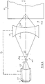
- the present invention offers another solution, the block diagram of which is illustrated in FIG. 3.
- a high frequency pulse generator G10 is connected by a directional coupler CD to the two electrodes of an ultrasonic transducer T.
- the echoes received by this transducer are transmitted by the coupler CD to an echo reception and analysis circuit noted R10 .
- this device has in common with that of FIG. 1 the fact that a lens L1 is formed of a cylindrical bar whose front face L11, flat, receives the ultrasonic transducer T. Its rear face L12 is machined like a spherical or cylindrical diopter centered in C1. The image focal point associated with this diopter L12 is at F in FIG. 3.
- the acoustic radiation from this first lens L1 is applied to a second lens L2, which is here a biconcave lens, formed of two spherical or cylindrical diopters, L21 on the inside, and L22 on the outside, facing the EC sample.
- the internal diopter L21 centered at C2, is positioned here so that its object focal point is the image focal point F of the internal diopter L12.
- the acoustic lens L2 is then crossed by a parallel acoustic beam, in other words a plane wave, which passes through the material constituting the lens L2, namely corundum.
- the combination of lenses L1 and L2 makes it possible to obtain focusing at variable distance.
- the internal diopter L12 of the first lens L1 associated with the internal diopter L21 of the second lens L2 constitutes a beam-expanding system in the application presented, which is the acoustic inspection of a sample of ceramic material. It can also be used as a beam reducer in other applications such as measuring the thickness of coatings (paints).
- the acoustic beam is substantially parallel to the axis of the system inside the lens L2, and the focusing depth is given by: where e is the thickness of the coupling medium, which can be neglected in practice. Furthermore, n denotes here the relative index of the lens L2, n m denotes the index of the coupling medium relative to the material of the sample examined.
- a lithium niobate transducer which would have the shape of Figure 1, and which should illuminate such a large pupil, would have a radiation resistance of about 2 ohms.
- the invention makes it possible to produce said pupil, while retaining the electrical impedance adaptation required for the transducer, at the usual value of 50 ohms.
- the ratio between the radii of curvature of the diopters L21 and L12 is therefore equal to 5.
- the optimization of the geometry of the device also requires that the distance between the lenses L1 and L2 be minimized, in order to reduce as far as possible the travel time of the acoustic waves inside the device. Indeed, in acoustic microscopy, as in any other imaging application, it is necessary to keep a sufficient number of points on each line of the image.
- This transit time Tp is written: where e 1 and e 2 are the thicknesses of the lenses L1 and L2 respectively, v c is the speed of propagation of the ultrasound in the corundum, the two lenses being assumed to be made of corundum in this example, ⁇ is the difference between the two lenses with respect to the confocal position, and v H is the propagation speed of the acoustic waves in the coupling medium between the lenses L1 and L2.
- Corundum has various advantages including that of offering excessively low acoustic attenuation. There is therefore no constraint on the maximum dimensions to be given to the lenses L1 and L2. And we can even operate these at frequencies much higher than 100 megahertz. On the other hand, such constraints on the dimensions may occur if the output lens L2 is made of silica or sintered alumina.
- Corundum still has the distinction of being an anisotropic material, unlike silica or sintered alumina, and it belongs to the trigonal crystallographic system.
- the acoustic wave is practically a plane wave.
- the corundum has a slightly focusing section for energy, that is to say that the diffraction is less important than expected, and that the performances are a little better than that which is given by the relationships set out above.
- A is as before the distance between the focal point of the diopter L12 of the lens L1, and that of the diopter L21 of the lens L2; d is the thickness of the exit lens, R 2 is the radius of curvature of the diopter L21, R 3 is the radius of curvature of the diopter L22, and n is the refractive index (assumed to be the same) associated with the diopters L12 , L21 and L22.
- FIG. 4 illustrates the same lenses L1 and L2 in a different relative position, where the focal point F1 of the diopter L12 is spaced from the focal point F2 of the diopter L21.
- the thick dashed line M provisionally schematizes the frame which will connect the lenses L1 and L2 to allow their relative displacement, as will be seen below.
- FIG. 9 illustrates the relationship between the focusing distance f, counted from the top of the diopter L22 of the lens L2 and the spacing A between the focal points F1 and F2, this spacing being positive when F2 is to the right of F1.
- the equivalent focal distance of the lens in water varies from 0 (focusing on the output diopter L22) to 7 cm. This corresponds to a variation in the focusing distance in a ceramic sample which goes practically from the surface of the sample up to 10 mm in depth, which solves the problem posed.
- the losses at each diopter crossing are approximately 9 dB. With mercury, they reduce to less than 1 dB. (If we switch to silica lenses, these losses would be 4.5 dB and 0.2 dB respectively).
- the better transmission which results from this choice of the coupling medium is also accompanied by a significant reduction in the amplitude of the multiple echoes in the probe.
- mercury also has the advantage of attenuating very little the acoustic waves, which allows large variations in the parameter. This does not result in a significant modification of the losses in the probe. In particular, for the above-mentioned variation from +3 to -6 mm, the losses in the probe would only vary by around 4.5 dB.
- the coupling medium MC1 between the lens L1 and the lens L2 a liquid medium, of low propagation speed, of high acoustic impedance, and having a low attenuation at the acoustic waves. It has been observed that mercury and possibly gallium meet these conditions.
- the lens L22 is mechanically adapted to the coupling medium with the sample, which is water.
- This quarter wave layer performs an anti-reflection function. It is not necessary with mercury.
- the diopter L21 is covered with a layer of a few hundred nanometers of a chromium-gold alloy, which facilitates the wetting of the mercury on its surface by the formation of an amalgam. The same is done for the inner face of the frame M22, as well as of the frame M21 (FIG. 6) which cooperates with it, and the inner diopter L12 of the lens L1.
- the lens L1 for its part, can be of the type of conventional lenses used in acoustic microscopy.
- a corundum bar is provided at one of its ends with a piezoelectric transducer, for example made of lithium niobate, provided with suitable armatures, and capable of generating a longitudinal plane wave inside the bar.
- a piezoelectric transducer for example made of lithium niobate, provided with suitable armatures, and capable of generating a longitudinal plane wave inside the bar.
- an L12 diopter is machined which is polished and rigorously centered on the axis of the corundum bar.
- the diopter 12 is also well centered on its mount M21, which moves around the mount M22 in the embodiment of FIG. 6.
- the diopter L12 is first machined, so that it is centered on the axis of the corundum cylinder L1.
- the electrode is evaporated on the L11 face of the corundum bar.
- the transducer is placed on this electrode.
- a counter electrode is then evaporated on the transducer T, taking care that this counter electrode is well centered on the axis of the corundum cylinder.
- the corundum bar is then placed in the frame M 21 or M31 so that the axis of the latter coincides with that of the cooperating frame M22 or M32 as the case may be.
- An alternative embodiment consists in machining the lens L1 once mounted in its frame M31, and in doing the same for the evaporation of the counter-electrode.
- FIGS. 8, 8A and 8B illustrate a detailed embodiment of the device of the invention, in which provision is made for a controlled leak of the coupling medium, the latter being typically mercury.
- the assembly is similar to that of FIG. 7.
- the corundum bar L1 is mounted on the frame M41, of which an external thread 410 cooperates with an internal thread 420 of an enlarged part 425 of the frame M42 of the biconcave lens L2.
- a leak exists between the M41 and M42 mounts, through one or more flats 415 of the M41 mount.
- This slot ends in the reservoir 400 formed between 425 and M41. This avoids almost all of the problems encountered with mercury, given the variable volume that will exist between the lenses L1 and L2. In particular, the presence of air bubbles, or the introduction of vibrations would be very damaging, especially for imaging applications.
- the bore 417 receives an adapter body of the transducer T, held by a transverse screw 418 (FIG. 8B).
- the larger terminal bore 419 is used to house the adapter electronics for the transducer.
Landscapes
- Physics & Mathematics (AREA)
- Engineering & Computer Science (AREA)
- Acoustics & Sound (AREA)
- Multimedia (AREA)
- Investigating Or Analyzing Materials By The Use Of Ultrasonic Waves (AREA)
- Ultra Sonic Daignosis Equipment (AREA)
- Instruments For Viewing The Inside Of Hollow Bodies (AREA)
Claims (15)
Priority Applications (1)
| Application Number | Priority Date | Filing Date | Title |
|---|---|---|---|
| AT86400354T ATE45642T1 (de) | 1985-02-28 | 1986-02-19 | Akustisches geraet mit mehreren linsen und regelbarer verstaerkung und regelbarem brennpunkt. |
Applications Claiming Priority (2)
| Application Number | Priority Date | Filing Date | Title |
|---|---|---|---|
| FR8502977 | 1985-02-28 | ||
| FR8502977A FR2578081B1 (fr) | 1985-02-28 | 1985-02-28 | Dispositif acoustique multi-lentilles a grandissement et focale variables |
Publications (2)
| Publication Number | Publication Date |
|---|---|
| EP0193457A1 EP0193457A1 (de) | 1986-09-03 |
| EP0193457B1 true EP0193457B1 (de) | 1989-08-16 |
Family
ID=9316743
Family Applications (1)
| Application Number | Title | Priority Date | Filing Date |
|---|---|---|---|
| EP86400354A Expired EP0193457B1 (de) | 1985-02-28 | 1986-02-19 | Akustisches Gerät mit mehreren Linsen und regelbarer Verstärkung und regelbarem Brennpunkt |
Country Status (4)
| Country | Link |
|---|---|
| EP (1) | EP0193457B1 (de) |
| AT (1) | ATE45642T1 (de) |
| DE (1) | DE3665109D1 (de) |
| FR (1) | FR2578081B1 (de) |
Families Citing this family (3)
| Publication number | Priority date | Publication date | Assignee | Title |
|---|---|---|---|---|
| CN102264304B (zh) * | 2008-10-15 | 2014-07-23 | 罗切斯特大学 | 利用多功能声透镜的光声成像 |
| CN108838747A (zh) * | 2018-08-10 | 2018-11-20 | 天津大学 | 一种基于声透镜的超声聚焦流体振动抛光系统 |
| WO2024227279A1 (zh) * | 2023-05-04 | 2024-11-07 | 中国科学院深圳先进技术研究院 | 一种全息声镊装置及其全息声场生成方法 |
Family Cites Families (4)
| Publication number | Priority date | Publication date | Assignee | Title |
|---|---|---|---|---|
| US3934460A (en) * | 1973-08-06 | 1976-01-27 | General Electric Company | Apparatus for focusing and collimating ultrasonic waves |
| GB1498843A (en) * | 1974-03-29 | 1978-01-25 | Westinghouse Electric Corp | Acoustic camera apparatus |
| EP0131653A1 (de) * | 1983-07-19 | 1985-01-23 | N.V. Optische Industrie "De Oude Delft" | Einrichtung zum berührungsfreien Zertrümmern von im Körper befindlichen steinigen Gegenständen mittels Schallschockwellen |
| DE3328051A1 (de) * | 1983-08-03 | 1985-02-14 | Siemens AG, 1000 Berlin und 8000 München | Einrichtung zum beruehrungslosen zertruemmern von konkrementen |
-
1985
- 1985-02-28 FR FR8502977A patent/FR2578081B1/fr not_active Expired
-
1986
- 1986-02-19 DE DE8686400354T patent/DE3665109D1/de not_active Expired
- 1986-02-19 EP EP86400354A patent/EP0193457B1/de not_active Expired
- 1986-02-19 AT AT86400354T patent/ATE45642T1/de not_active IP Right Cessation
Also Published As
| Publication number | Publication date |
|---|---|
| ATE45642T1 (de) | 1989-09-15 |
| DE3665109D1 (en) | 1989-09-21 |
| FR2578081B1 (fr) | 1987-05-07 |
| FR2578081A1 (fr) | 1986-08-29 |
| EP0193457A1 (de) | 1986-09-03 |
Similar Documents
| Publication | Publication Date | Title |
|---|---|---|
| EP0385897A1 (de) | Mikro-echographische Sonde mit Ultraschallfokussierung durch eine verformbare Oberfläche | |
| EP2054171B1 (de) | Akustischer hochleistungsresonator mit integrierten optischen schnittstellenelementen | |
| EP0150779B1 (de) | Kontaktlinse zur Beobachtung und Behandlung des Auges mit Lichtbestrahlung | |
| EP0161645B1 (de) | Kontaktglas für Ophthalmoskopie und Laserstrahlen-Ophthalmotherapie | |
| Park et al. | Optically Transparent Focused Transducers for Combined Photoacoustic and Ultrasound Microscopy: S. Park et al. | |
| EP2020896A1 (de) | Miniaturisierter optischer kopf mit hoher räumlicher auflösung und hoher sensitivität, insbesondere für konfokale faser-fluoreszenz-darstellung | |
| WO2003056379A1 (fr) | Tete optique de focalisation miniaturisee, notamment pour endoscope | |
| CN103940796A (zh) | 新型多角度多模式快速切换环状光学照明显微成像系统 | |
| EP0193457B1 (de) | Akustisches Gerät mit mehreren Linsen und regelbarer Verstärkung und regelbarem Brennpunkt | |
| EP0540111B1 (de) | Hochfrequenz akustisches Rheometer, und dieses Rheometer verwendende Vorrichtung zur Messung der Viskosität eines Fluides | |
| EP0176415B1 (de) | Akustisches Mikroskop mit asphärischen Linsen für Untersuchungen im Inneren eines Objektes | |
| EP0426571A1 (de) | Verfahren zur pünktlichen spektroskopischen Analyse von durch eine in einem Nahfeld liegende Substanz gebeugtem oder absorbiertem Licht | |
| EP0219519B1 (de) | Verfahren zur zerstörungsfreien feststellung von zumindest einem punkt einer rissebildungsvorderseite in einem werkstück und vorrichtung zur durchführung desselben | |
| EP0005116B1 (de) | Verfahren zur Untersuchung eines Stückes mittels eines Strahlungsbündels | |
| EP0109886B1 (de) | Akusto-optische Anordnung zur Analyse von Spektren | |
| Ashkenazi et al. | High frequency ultrasound imaging using Fabry-Perot optical etalon | |
| CN116519594A (zh) | 一种跨尺度光声成像系统 | |
| FR2531854A1 (fr) | Appareil de mesure non invasive de la vitesse moyenne du courant sanguin dans des tissus vivants | |
| EP1472532B1 (de) | Verfahren und vorrichtung zur überprüfung von röhrchen mit ultraschall | |
| Toader et al. | Ultraviolet optical-resolution photoacoustic microscopy of fresh tissue slices using a static ultrasound detector and fast galvo scanning | |
| FR3051562A3 (fr) | Systeme de stimulation par ultrasons d'un echantillon in vitro | |
| RU2603819C2 (ru) | Оптоакустический объектив | |
| Thaer | Complementary and Analogous Information Obtained by Acoustic and Light Microscopy | |
| Perez-Cota et al. | Thin-film transducers for the detection and imaging of Brillouin oscillations in transmission on cultured cells | |
| WO2024117900A1 (en) | Method and system for imaging subsurface features inside a substrate |
Legal Events
| Date | Code | Title | Description |
|---|---|---|---|
| PUAI | Public reference made under article 153(3) epc to a published international application that has entered the european phase |
Free format text: ORIGINAL CODE: 0009012 |
|
| AK | Designated contracting states |
Kind code of ref document: A1 Designated state(s): AT BE CH DE FR GB IT LI LU NL SE |
|
| 17P | Request for examination filed |
Effective date: 19870114 |
|
| 17Q | First examination report despatched |
Effective date: 19881025 |
|
| GRAA | (expected) grant |
Free format text: ORIGINAL CODE: 0009210 |
|
| AK | Designated contracting states |
Kind code of ref document: B1 Designated state(s): AT BE CH DE FR GB IT LI LU NL SE |
|
| REF | Corresponds to: |
Ref document number: 45642 Country of ref document: AT Date of ref document: 19890915 Kind code of ref document: T |
|
| REF | Corresponds to: |
Ref document number: 3665109 Country of ref document: DE Date of ref document: 19890921 |
|
| GBT | Gb: translation of ep patent filed (gb section 77(6)(a)/1977) | ||
| ITF | It: translation for a ep patent filed | ||
| PLBE | No opposition filed within time limit |
Free format text: ORIGINAL CODE: 0009261 |
|
| STAA | Information on the status of an ep patent application or granted ep patent |
Free format text: STATUS: NO OPPOSITION FILED WITHIN TIME LIMIT |
|
| 26N | No opposition filed | ||
| PGFP | Annual fee paid to national office [announced via postgrant information from national office to epo] |
Ref country code: LU Payment date: 19910122 Year of fee payment: 6 |
|
| PGFP | Annual fee paid to national office [announced via postgrant information from national office to epo] |
Ref country code: BE Payment date: 19910131 Year of fee payment: 6 |
|
| PGFP | Annual fee paid to national office [announced via postgrant information from national office to epo] |
Ref country code: SE Payment date: 19910208 Year of fee payment: 6 |
|
| PGFP | Annual fee paid to national office [announced via postgrant information from national office to epo] |
Ref country code: GB Payment date: 19910212 Year of fee payment: 6 |
|
| PGFP | Annual fee paid to national office [announced via postgrant information from national office to epo] |
Ref country code: AT Payment date: 19910214 Year of fee payment: 6 |
|
| PGFP | Annual fee paid to national office [announced via postgrant information from national office to epo] |
Ref country code: FR Payment date: 19910215 Year of fee payment: 6 |
|
| ITTA | It: last paid annual fee | ||
| PGFP | Annual fee paid to national office [announced via postgrant information from national office to epo] |
Ref country code: NL Payment date: 19910228 Year of fee payment: 6 |
|
| PGFP | Annual fee paid to national office [announced via postgrant information from national office to epo] |
Ref country code: DE Payment date: 19910326 Year of fee payment: 6 |
|
| EPTA | Lu: last paid annual fee | ||
| PGFP | Annual fee paid to national office [announced via postgrant information from national office to epo] |
Ref country code: CH Payment date: 19910513 Year of fee payment: 6 |
|
| PG25 | Lapsed in a contracting state [announced via postgrant information from national office to epo] |
Ref country code: LU Free format text: LAPSE BECAUSE OF NON-PAYMENT OF DUE FEES Effective date: 19920219 Ref country code: GB Effective date: 19920219 Ref country code: AT Effective date: 19920219 |
|
| PG25 | Lapsed in a contracting state [announced via postgrant information from national office to epo] |
Ref country code: SE Effective date: 19920220 |
|
| PG25 | Lapsed in a contracting state [announced via postgrant information from national office to epo] |
Ref country code: BE Effective date: 19920228 |
|
| PG25 | Lapsed in a contracting state [announced via postgrant information from national office to epo] |
Ref country code: LI Effective date: 19920229 Ref country code: CH Effective date: 19920229 |
|
| BERE | Be: lapsed |
Owner name: CENTRE NATIONAL DE LA RECHERCHE SCIENTIFIQUE CNRS Effective date: 19920228 |
|
| PG25 | Lapsed in a contracting state [announced via postgrant information from national office to epo] |
Ref country code: NL Effective date: 19920901 |
|
| GBPC | Gb: european patent ceased through non-payment of renewal fee | ||
| NLV4 | Nl: lapsed or anulled due to non-payment of the annual fee | ||
| PG25 | Lapsed in a contracting state [announced via postgrant information from national office to epo] |
Ref country code: FR Effective date: 19921030 |
|
| REG | Reference to a national code |
Ref country code: CH Ref legal event code: PL |
|
| PG25 | Lapsed in a contracting state [announced via postgrant information from national office to epo] |
Ref country code: DE Effective date: 19921103 |
|
| REG | Reference to a national code |
Ref country code: FR Ref legal event code: ST |
|
| EUG | Se: european patent has lapsed |
Ref document number: 86400354.6 Effective date: 19920904 |
|
| PG25 | Lapsed in a contracting state [announced via postgrant information from national office to epo] |
Ref country code: IT Free format text: LAPSE BECAUSE OF NON-PAYMENT OF DUE FEES;WARNING: LAPSES OF ITALIAN PATENTS WITH EFFECTIVE DATE BEFORE 2007 MAY HAVE OCCURRED AT ANY TIME BEFORE 2007. THE CORRECT EFFECTIVE DATE MAY BE DIFFERENT FROM THE ONE RECORDED. Effective date: 20050219 |