EP0193458B1 - Herstellung von Rädern zum Korrigieren des ungleichförmigen Drehens einer pneumatischen Reifen- und Radzusammensetzung - Google Patents
Herstellung von Rädern zum Korrigieren des ungleichförmigen Drehens einer pneumatischen Reifen- und Radzusammensetzung Download PDFInfo
- Publication number
- EP0193458B1 EP0193458B1 EP86400356A EP86400356A EP0193458B1 EP 0193458 B1 EP0193458 B1 EP 0193458B1 EP 86400356 A EP86400356 A EP 86400356A EP 86400356 A EP86400356 A EP 86400356A EP 0193458 B1 EP0193458 B1 EP 0193458B1
- Authority
- EP
- European Patent Office
- Prior art keywords
- rim
- disc
- wheel
- bead seat
- axis
- Prior art date
- Legal status (The legal status is an assumption and is not a legal conclusion. Google has not performed a legal analysis and makes no representation as to the accuracy of the status listed.)
- Expired
Links
- 238000004519 manufacturing process Methods 0.000 title claims description 19
- 239000011324 bead Substances 0.000 claims description 97
- 238000000034 method Methods 0.000 claims description 17
- 230000000295 complement effect Effects 0.000 claims description 5
- 230000001154 acute effect Effects 0.000 claims description 4
- 230000008878 coupling Effects 0.000 claims 2
- 238000010168 coupling process Methods 0.000 claims 2
- 238000005859 coupling reaction Methods 0.000 claims 2
- 238000003825 pressing Methods 0.000 claims 2
- 230000000717 retained effect Effects 0.000 claims 1
- 230000015572 biosynthetic process Effects 0.000 description 3
- 230000006835 compression Effects 0.000 description 3
- 238000007906 compression Methods 0.000 description 3
- 229910000831 Steel Inorganic materials 0.000 description 2
- 230000000712 assembly Effects 0.000 description 2
- 238000000429 assembly Methods 0.000 description 2
- 230000002093 peripheral effect Effects 0.000 description 2
- 239000010959 steel Substances 0.000 description 2
- 238000004458 analytical method Methods 0.000 description 1
- 238000003491 array Methods 0.000 description 1
- 238000010276 construction Methods 0.000 description 1
- 230000000694 effects Effects 0.000 description 1
- 238000005516 engineering process Methods 0.000 description 1
- 239000000446 fuel Substances 0.000 description 1
- 238000003780 insertion Methods 0.000 description 1
- 230000037431 insertion Effects 0.000 description 1
- 238000003754 machining Methods 0.000 description 1
- 239000002184 metal Substances 0.000 description 1
- 230000000284 resting effect Effects 0.000 description 1
- 238000000926 separation method Methods 0.000 description 1
- 210000003371 toe Anatomy 0.000 description 1
Images




Classifications
-
- B—PERFORMING OPERATIONS; TRANSPORTING
- B21—MECHANICAL METAL-WORKING WITHOUT ESSENTIALLY REMOVING MATERIAL; PUNCHING METAL
- B21D—WORKING OR PROCESSING OF SHEET METAL OR METAL TUBES, RODS OR PROFILES WITHOUT ESSENTIALLY REMOVING MATERIAL; PUNCHING METAL
- B21D53/00—Making other particular articles
- B21D53/26—Making other particular articles wheels or the like
-
- Y—GENERAL TAGGING OF NEW TECHNOLOGICAL DEVELOPMENTS; GENERAL TAGGING OF CROSS-SECTIONAL TECHNOLOGIES SPANNING OVER SEVERAL SECTIONS OF THE IPC; TECHNICAL SUBJECTS COVERED BY FORMER USPC CROSS-REFERENCE ART COLLECTIONS [XRACs] AND DIGESTS
- Y10—TECHNICAL SUBJECTS COVERED BY FORMER USPC
- Y10T—TECHNICAL SUBJECTS COVERED BY FORMER US CLASSIFICATION
- Y10T29/00—Metal working
- Y10T29/49—Method of mechanical manufacture
- Y10T29/49481—Wheel making
- Y10T29/49492—Land wheel
- Y10T29/49496—Disc type wheel
-
- Y—GENERAL TAGGING OF NEW TECHNOLOGICAL DEVELOPMENTS; GENERAL TAGGING OF CROSS-SECTIONAL TECHNOLOGIES SPANNING OVER SEVERAL SECTIONS OF THE IPC; TECHNICAL SUBJECTS COVERED BY FORMER USPC CROSS-REFERENCE ART COLLECTIONS [XRACs] AND DIGESTS
- Y10—TECHNICAL SUBJECTS COVERED BY FORMER USPC
- Y10T—TECHNICAL SUBJECTS COVERED BY FORMER US CLASSIFICATION
- Y10T29/00—Metal working
- Y10T29/53—Means to assemble or disassemble
- Y10T29/53448—Vehicle wheel
Definitions
- the present invention relates to the art of vehicle wheel manufacture, and more particularly to correction of variations in lateral runout and/or lateral forces in a rotating pneumatic tire and wheel assembly.
- a problem long-standing in the art lies in the production of pneumatic tire and wheel assemblies which, when assembled and operated on a vehicle, run true about the axis of rotation. Forces generated by any circumferential variations in the tire carcass or wheel cause vibrations, which in turn lead to dissatisfied customers and significant warranty claims against automobile manufacturers.
- the present trend among manufacturers toward higher tire inflation pressures and smaller vehicles to improve fuel economy accentuates this problem so that rotational uniformity of the tire and wheel assembly has become more critical than in the past.
- Rotational non-uniformities in the tire and wheel assembly may possess both radial and axial components. Either or both of such components may be due to manfacturing inaccuracies in the wheel and/or in the tire mounted thereon.
- Axial characteristics, i.e. runout or force vibrations in the direction of the wheel and tire axis, are termed "lateral" characteristics in the art and in the present application.
- a disc having a circular array of bolt openings adapted to receive mounting studs for mounting the wheel to a vehicle, and a center pilot opening adapted to be received over the wheel hub.
- a number of techniques have been proposed for accomplishing this result, including formation of the bolt and center openings with a single tool while locating off of the bead seats, machining the center opening while locating off of pre-formed bolt-mounting openings, and circumferentially permanently deforming the rim bead seats while locating off of the bolt-mounting and/or center-pilot openings.
- a pretested tire having the location of the complementary peak of the first harmonic of radial force variation marked thereon, may then be assembled onto the wheel such that the respective tire and wheel harmonics are complementary and thereby tend to cancel each other. It likewise has been and remains conventional practice in the wheel manufacturing industry to attempt to form true-running wheels of minimum lateral runout - i.e. wherein the mounting plane defined by the inboard surface of the wheel disc in the region of the bolt-mounting openings is parallel to the average plane of the rim bead seats.
- a further and yet more specific object of the invention is to provide an economical and accurate method of assembling a pre-formed wheel disc to a pre-formed rim wherein the plane of the disc mounting surface is accurately located with respect to the average plane of the rim bead seats, and to provide an apparatus for performing such method and a wheel resulting from application thereof.
- a further object of the invention is to provide a wheel manufacturing method and apparatus which accomplishes the foregoing and which is economical to implement in mass production of vehicle wheels.
- the apparatus of the invention may be implemented in manufacture of true-running wheels wherein the mounting plane and the average bead seat plane are nominally parallel, or in the manufacture of wheels in accordance with another aspect of the invention wherein the low point or high point of the first harmonic of average bead seat lateral runout (with respect ot the mounting plane) is disposed at an acute angle by an amount and in a direction predetermined to locate such low point or high point of the first harmonic of bead seat lateral runout circumferentially adjacent to a selected location on the wheel rim, most preferably the rim valve opening.
- a still further object of the invention thus contemplates provision of pneumatic tire and wheel assembly which obtains improved ride characteristics by "match mounting" a wheel having controlled lateral runout per the foregoing object with a pneumatic tire pretested and having the complementary peak of the first harmonic of lateral force variation marked thereon, so that such lateral runout and lateral force variation harmonics tend to cancel eath other.
- the apparatus in accordance with the invention includes in a prefered embodiment a circumferential array of bead seat locating jaws which are individually adjustable axially of such array for selective orientation of the average bead set plane of a preformed wheel rim resting thereon.
- the bead seat locating jaws include sections for locating both the inboard and outboard bead seat regions of a one-piece rim for a pneumatic tubeless tire, such that the average plane of the bead seat regions is located more accurately and the rim is more fixedly held during the press-fit operation.
- the bead seat locators may be adjusted during a setup operation so that the mounting plane of the wheel disc pressed into a rim held by the bead seat locators is nominally parallel to the average bead seat plane, so that the resulting wheel is substantially true-running in lateral characteristics.
- the bead seat locators may be adjusted during a setup operation so that the average bead seat plane is intentionally disposed at an acute angle with respect to the disc mounting plane by an amount and in a direction empirically selected to place a peak of the first harmonic of lateral runout adjcent to a preselected circumferential location on the wheel rim, such as the rim valve hole.
- Such wheels, having controlled lateral eccentricity, may then be mounted to pretested tires so that the lateral characteristics thereof tend to cancel.
- the preformed discs employed in accordance with the present invention may have bolt-mounting and center-pilot openings already formed therein as disclosed in the above US-A 3,143,377, it is preferred that such openings be formed at a later stage of manufacture in the rim and disc assembly in accordance with the teachings of one or more of the U. S. patents noted above and assigned to the applicant hereof.
- FIG. 1 illustrates a pneumatic tire and wheel assembly 10 as comprising a conventional tubeless pneumatic tire 12 mounted on a two-piece fabricated steel wheel 16.
- wheel 16 includes a one-piece drop center wheel rim 18 having a rim base 19 and inboard and outboard circumferential bead seat regions 20 and 22 for receiving respective inboard and outboard bead toes of tire 12 in the usual manner.
- Bead seat regions 20,22 include the usual bead retaining flanges 24,26 respectively.
- Each bead seat region 20,22 may be considered conceptually to lie in or define an associated bead seat plane 28,30 (FIG. 2) which in theory are planar and parallel to each other but may not be planar or parallel in practice due to manufacturing variations and tolerances.
- Bead seat planes 28,30 together define an average bead seat plane illustrated at 32.
- the individual (average) bead seat planes 28,30, as well as the location and orientation of the average plane 32 of the two bead seats, may be located using conventional Fourier analysis techniques.
- a wheel mounting disc 34 includes a peripheral flange 36 press-fitted into and welded to rim base 19, and a disc body 37 which internally spans rim 18 for mounting wheel 16 to a vehicle.
- Bolt openings 40 are formed in a circular array, one in each of the slightly raised bolt-hole islands 39 (FIG. 2).
- the inboard surface of disc body 37 in the region of bolt openings 40 defines a wheel mounting surface having the average plane 42, which engages the wheel mounting spindle when the wheel is bolted thereto.
- bead seat planes 28,30 controls lateral runout characteristics of wheel 16.
- the relationship of bead seat planes 28,30 to each other is determined during preforming of the rim.
- the present invention addresses the relationship of disc mounting plane 42 to bead seat planes 28,30. It has become conventional practice in recent years to preform rim 18 and disc 34, with the configuration of FIG. 2 being exemplary, and to join the rim to the disc prior to formation of the bolt-mounting and center-pilot openings in the disc body.
- US-A 4,279,287 and US-A 4,354,407 identified hereinabove disclose methods and apparatus for forming such bolt-mounting and center-pilot openings in a preassembled rim and disc.
- the present invention is directed to assembly of a preformed disc 34 to a preformed rim 18, preferably prior to formation of the bolt-mounting and center-pilot openings in the disc body. It will be understood, however, that it is within the scope of the invention to employ a disc body having the bolt- . mounting and center-pilot openings formed therein prior to assembly to the rim.
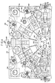
- FIGS. 3-7 collectively illustrate an exemplary but preferred press apparatus 50 for press-fitting a preformed disc 34 into a preformed rim 18.
- Apparatus 50 includes a fixed support base or platform 52.
- a circumferential array 54 of twelve bead seat locators 54A-54L are arrayed on platform 52 at equal angular increments around the central axis 56 (FIGS. 3-4) of apparatus 50.
- Bead seat locators 54A-54L are of generally identical construction. Locator 54A will be described in detail. Corresponding elements of the remaining locators, where illustrated in the drawings, are identified by correspondingly identical reference numerals.
- Bead seat locator 54A includes a lower first locator section 60 (FIG. 3) which, in combination with the first section of the remaining locators 54B-54L, collectively engage and fixture the outboard head seat region 22 of wheel rim 18.
- Bead seat region is employed in a general sense and includes at least that portion of the bead retaining flange contiguous with the bead seat.
- Bead seat locator section 60 includes a locator pad 62 having an upper surface contoured to engage bead seat region 22, and a lower surface affixed by bolts 64 to an upper wedge block 66.
- Upper wedge block 66 is maintained in a fixed position radially of axis 56 by the radially spaced pins 68 which depend from block 66 and are slidably received into corresponding locator bores on support platform 52.
- Upper wedge block 66 has an inclined lower surface which is slidably carried on a complementarily inclined upper surface of a lower wedge block 70.
- Lower wedge block 70 has slotted apertures 72 through which pins 68 extend, and is itself slidably received in a radially oriented guideway or slot 74 on base 52.
- lower wedge block 70 is restrained by pins 68 and guideway 74 to radial motion with respect to axis 56
- upper wedge block 66 is restrained by pins 68 to axial motion parallel to axis 56 as a function of radial motion of lower wedge block 70.
- a threaded stud 76 (FIGS. 3 and 7) has a head 78 rotatably carried at the radially outer end of lower wedge block 70 and projects radially outwardly therefrom through a threaded opening in a block 80 affixed to support base 52.
- stud 76 adjusts radial position of lower wedge block 70, which in turn adjusts axial position of upper wedge block 66 and pad 62 relative to central axis 56.
- a pin 81 projects upwardly from pad 62 of locator 54A (but not locators 54B-54L) parallel to axis 56 for receipt into the preformed valve hole 38 on rim 18, thereby accurately and repeatably locating each rim angularly of axis 56.
- Bead seat locator 54A further includes a second locator section 82 which, in cooperation with the corresponding second sections of bead seat locators 54B-54L, collectively engage and fixture the inboard bead seat region 20 of wheel rim 18.
- Locator section 82 includes a base 84 slidably carried in a radial slot 86 on the upper surface of upper wedge block 66. Slot 86 thus forms a guideway for motion of base 84 in the radial direction relative to axis 56.
- a shaft 88 is affixed by the pin 90 (FIG. 3) to base 84 and projects radially outwardly therefrom slidably through a spring block 92 affixed to the upper surface of wedge block 66 by the bolts 93 (FIG.
- a coil spring 94 is captured in compression between block 92 and the jam nuts 96 threaded onto the radially outer end of shaft 88 for normally biasing base 84 radially outwardly with respect to axis 56.
- a pad adapter 98 is affixed to base 84 by the bolts 100 and projects radially inwardly therefrom.
- An inboard bead seat locator pad 102 is mounted on an axially facing ledge of adapter 98 by the bolt 104. Shim pieces 106,108 respectively separate adapter 98 from base 84 and pad 102 from adapter 98 for adjusting the radial and axial positions of pad 102 respectively.
- the upper radially inner edge of pad 102 is adapted for facing engagement with inboard bead seat region 20 of rim 18.
- a cam roller 110 is rotatable on a shaft 112 within a slot 114 adjacent to the upper radially outer edge of base 84.
- An upper die holder 116 (FIG. 3) is coupled to a controlled hydraulic ram 118 for reciprocal motion in the direction of axis 56.
- An upper press die head 120 is affixed by bolts 121 to and depends from holder 116 coaxially with axis 56.
- a die pressure plate 122 is coaxially affixed to die head 120 by the bolts 124 and has planar lower surface 126 accurately positioned perpendicular to axis 56.
- An annular outwardly flaring horn 128 surrounds planar die plate surface 126 and is contoured to engage and support the mid-portion of disc 34 when the inboard mounting surface thereof is pressed against planar surface 126.
- a pressure ring 130 surrounds and is slidably carried on the radially facing surface of die head 120 for axial motion with respect thereto.
- the lower surface 132 of pressure ring 130 is contoured to engage the inboard bead retaining flange 24 of rim 18 and thereby hold inboard seat region 20 in accurate position against the bead seat locators 54A-54L.
- a circumferential array of hydraulic springs 134 is carried by holder 116 and have actuators 136 which depend therefrom in position to engage and exert uniform axial pressure upon the planar upper surface 138 of pressure ring 130.
- a lower die head 140 (FIGS. 3-4) is mounted on base 52 for reciprocation in the direction of axis 56.
- Die head 140 includes a hollow shaft 142 (FIG. 3 ) which projects downwardly through a sleeve bearing 144 in base 52 coaxially with axis 56.
- a coil spring 146 is captured in compression within shaft 142 and engages the bottom wall of a cup 148 affixed by bolts 149 to base 52 for normally biasing lower die head 140 upwardly with respect to the support base. Reciprocal motion of die head 140 with respect to base 52 is guided by a circumferential array of pins 150 carried by base 52 and slidable within corresponding bores 152 in die head 140, only one such pin being illustrated in FIG. 3.
- a lower die pressure plate 154 is affixed by the bolts 156 to lower die head 140 and has an upper surface contoured to engage the outboard face of disc 34.
- An oval hub 158 projects centrally upwardly from pressure plate 154 and is received within a corresponding oval opening in preformed disc 34 for locating the disc bolt-hole islands angularly of axis 56.
- a circumferentially continuous actuator ring 160 (FIGS. 3-6) is slidably carried on the circumferentially spaced guide pins 162 (FIGS. 4 and 6) which are affixed to and project upwardly from support base 52, and is biased upwardly with respect to the support base by the circumferentially spaced coil springs 164 (FIGS. 4 and 5).
- Guide pins 162 each have an enlarged annular head 166 which cooperates with a counterbored guide pin opening 168 in ring 160 for limiting upward motion of ring 160 with respect to base 52.
- Each spring 164 is captured in compression between a spring cap 170 affixed to ring 160 by the bolts 172, and a spring locator pin 174 threaded into base 52 and projecting upwardly therefrom into the spring coils.
- a guide pin 162 is positioned between each pair of bead seat locators 54B, 54C, 54E, 54F, 54H, 541 and 54K, 54L.
- a spring 164 is positioned between the remaining adjacent bead seat locator pairs. The arrays of spring 164 and pins 162 are concentric.
- Orthogonally spaced fingers 176 integrally project outwardly from the body of ring 160 and slidably embrace comer guide posts 177 for additionally guiding motion of ring 160.
- Corner posts 177 are affixed to and project upwardly from base 52.
- Guide pins 162 are each aligned radially of axis 56 with a corresponding corner post 177.
- a plurality of circumferentially spaced actuator blocks 178 (FIGS. 3-4) are affixed by bolts 179 to and project radially inwardly from 160 in respective radial alignment with rollers 110 on the several bead seat locators 54A-54L.
- Each block 178 has a ramped lower inside surface 180 (FIG.
- An abutment ring 184 is affixed to and depends from upper die holder 116 for engagement of ring 160.
- Upper die holder 116 is apertured for sliding reception over comer guide posts 177.
- FIGS. 8-10 Successive stages of operation of apparatus 50 are illustrated in FIGS. 8-10.
- upper die holder 116 is spaced a substantial distance from base 52 to permit insertion of the preformed rim and disc elements.
- actuator ring 160 is biased upwardly (FIG. 8) by springs 164 out of engagement with bead seat locator 54A-54L, and upper disc locator sections 82 are biased by springs 94 radially outwardly to their normal or retracted positions.
- lower die head 140 is biased upwardly by spring 146.
- a pre- formed rim 18 is positioned on the several outboard bead seat locator pads 62, with pin 81 being received in the preformed rim valve hole for locating the rim circumferentially of press axis 56.
- a pre- formed disc 34 is then placed outboard face down upon the upper surface of lower die pressure plate 154, with hub 158 received in the preformed disc center opening. With the preformed rim and disc so located, upper die holder 116 is propelled by ram 118 to and through the position illustrated in FIG. 8 toward that illustrated in FIG. 9.
- the apparatus of the invention may be initially set up for operation by assembling a number of rims and discs in the manner described, and then checking such rim and disc assemblies for lateral runout in the usual manner.
- Lower ramp blocks 70 of the several bead seat locators 54A-54L are empirically individually adjusted by means of associated studs 76 to selectively axially position the outboard bead seat pads 62, and inboard bead seat pads 102 are individually adjustably positioned radially and axially by selective use of appropriate shims 106,108 respectively, to obtain desired lateral runout characteristics. It is desirable to obtain minimum lateral runout - i.e.
- an- gulate the average bead seat plane 32 with respect to the mounting plane 42 by an amount and in a direction selected so as to place the peak of the first harmonic of lateral runout adjacent to a preselected circumferential location on the rim, such as adjacent to rim valve hole 38.
- This is accomplished by individual selective adjustment of inboard bead seat locator pads 62, using wedge blocks 66,70 and studs 76 as previously described, and by appropriate selection of shims 108.
- the upper and lower bead seat locator sections and opposed pairs of locators are first adjusted to obtain minimum lateral runout, in the manner previously described.
- the bead seat locators are then adjusted in adjacent pairs to move the harmonic peak circumferentially around the wheel. It will be noted, in this connection, that the upper and lower bead seat locator sections of each locator are not readjusted relative to each other during this procedure. That is, the separation between the inboard and outboard bead seat locator faces remains constant.
- a wheel 16 having a first harmonic of lateral runout located adjacent to valve hole 38 is assembled to a tire 12 which is pretested to locate the complementary peak of the first harmonic of lateral force variation, which location is marked as at 14 (FIG. 1) on the tire sidewall, mark 14 is radially aligned with valve hole 38 so that the respective lateral first harmonics are out of phase and tend to cancel each other, thereby yielding a tire and wheel assembly having overall improved ride characteristics.
- the subject matter of the present invention may be combined - i.e. used in combination with - the subject matter of US-A 4,279,287 and US-A 4,354,407 to obtain a tire and wheel assembly having improved ride characteristics, in terms of both lateral and radial ride components. It has been found that lateral variations, due to lateral runout of the wheel and lateral force variation of the tire, do not contribute to undesirable ride characteristics as much as do radial runout and force variations, particularly when the lateral ride variations are held below a threshold level.
- the apparatus according to the invention may also be used to construct a wheel to possess minimum lateral runout by locating the average bead seat plane 32 (FIG. 2) parallel to the wheel mounting plane and to form the bolt and center-pilot openings in the wheel disc at a subsequent stage of manufacture so as to locate a peak of the first harmonic of radial runout adjacent to the valve hole, as described in the above noted U.S. patents.
Landscapes
- Engineering & Computer Science (AREA)
- Mechanical Engineering (AREA)
- Tyre Moulding (AREA)
- Tires In General (AREA)
- Automobile Manufacture Line, Endless Track Vehicle, Trailer (AREA)
Claims (12)
Applications Claiming Priority (2)
| Application Number | Priority Date | Filing Date | Title |
|---|---|---|---|
| US707137 | 1985-03-01 | ||
| US06/707,137 US4646434A (en) | 1985-03-01 | 1985-03-01 | Apparatus for wheel manufacture for correction of rotational non-uniformity of a pneumatic tire and wheel assembly |
Publications (3)
| Publication Number | Publication Date |
|---|---|
| EP0193458A2 EP0193458A2 (de) | 1986-09-03 |
| EP0193458A3 EP0193458A3 (en) | 1987-09-09 |
| EP0193458B1 true EP0193458B1 (de) | 1989-07-26 |
Family
ID=24840500
Family Applications (1)
| Application Number | Title | Priority Date | Filing Date |
|---|---|---|---|
| EP86400356A Expired EP0193458B1 (de) | 1985-03-01 | 1986-02-20 | Herstellung von Rädern zum Korrigieren des ungleichförmigen Drehens einer pneumatischen Reifen- und Radzusammensetzung |
Country Status (7)
| Country | Link |
|---|---|
| US (1) | US4646434A (de) |
| EP (1) | EP0193458B1 (de) |
| JP (1) | JPS61211102A (de) |
| KR (1) | KR860007041A (de) |
| BR (1) | BR8600826A (de) |
| CA (2) | CA1276438C (de) |
| DE (1) | DE3664576D1 (de) |
Families Citing this family (13)
| Publication number | Priority date | Publication date | Assignee | Title |
|---|---|---|---|---|
| US4897909A (en) * | 1988-12-29 | 1990-02-06 | Motor Wheel Corporation | Method for wheel manufacture by punch forming |
| US5193274A (en) * | 1992-01-24 | 1993-03-16 | Motor Wheel Corporation | Method and apparatus for manufacture of a vehicle wheel having controlled lateral runout characteristic |
| US5257569A (en) * | 1992-06-01 | 1993-11-02 | Motor Wheel Corporation | Apparatus for manufacture of vehicle wheels |
| US5380071A (en) * | 1993-03-15 | 1995-01-10 | Motor Wheel Corporation | Vehicle wheel and method of manufacture of the same |
| US5509726A (en) * | 1993-12-10 | 1996-04-23 | Motor Wheel Corporation | Variable off-set full face wheel and method for making the same |
| AUPO628197A0 (en) | 1997-04-17 | 1997-05-15 | Simmons, Anthony Grant | Joining metal components |
| AU719741B2 (en) * | 1997-04-17 | 2000-05-18 | Anthony Grant Simmons | Joining metal components |
| WO1999015306A1 (en) * | 1997-09-25 | 1999-04-01 | Hess Engineering, Inc. | Method and apparatus for assembly vehicle wheels |
| AU2400700A (en) | 1998-12-29 | 2000-07-31 | Hayes Lemmerz International, Inc. | Method and apparatus for producing a vehicle wheel |
| JP3479809B2 (ja) * | 2000-12-05 | 2003-12-15 | 本田技研工業株式会社 | バランスが調整されたホイール及びその製造方法 |
| CN101398285B (zh) * | 2008-10-20 | 2012-09-05 | 徐国林 | 钢圈轮辋跳动量检测过程 |
| US8353106B2 (en) * | 2009-07-06 | 2013-01-15 | Rimsmith Tool, LLC | Wheel/rim fixing device and method of using the same |
| CN118417815B (zh) * | 2024-07-02 | 2024-09-17 | 山东大业股份有限公司 | 一种轮胎钢圈校正装置 |
Family Cites Families (14)
| Publication number | Priority date | Publication date | Assignee | Title |
|---|---|---|---|---|
| US3143377A (en) * | 1960-09-26 | 1964-08-04 | Firestone Tire & Rubber Co | Wheel disks and disk wheel assemblies |
| NL259900A (de) * | 1960-09-26 | |||
| US3195491A (en) * | 1960-09-26 | 1965-07-20 | Firestone Tire & Rubber Co | Equipment for producing tapered disk wheels |
| US3530717A (en) * | 1969-04-22 | 1970-09-29 | Kelsey Hayes Co | Wheel rounding machine |
| US3688373A (en) * | 1970-03-05 | 1972-09-05 | Kelsey Hayes Co | Method of forming and rounding wheels |
| US3756063A (en) * | 1972-04-27 | 1973-09-04 | Grotnes Machine Works Inc | Shrink forming apparatus with axial run-out tooling |
| DE2224027A1 (de) * | 1972-05-17 | 1973-11-22 | Ford Werke Ag | Verfahren zur rund- und planlaufkorrektur von stahlblechscheibenraedern, insbesondere fuer kraftfahrzeuge |
| US3800600A (en) * | 1972-09-14 | 1974-04-02 | Kelsey Hayes Co | Method and apparatus for manufacturing vehicle wheels |
| US4106172A (en) * | 1976-04-07 | 1978-08-15 | Steel Stampings Limited | Vehicle wheels |
| US4074408A (en) * | 1976-06-21 | 1978-02-21 | Fdi, Inc. | Method for making vehicle wheel assembly |
| US4143449A (en) * | 1977-09-16 | 1979-03-13 | Kelsey-Hayes Co. | Wheel forming machine |
| US4304034A (en) * | 1979-03-12 | 1981-12-08 | David Trevarrow | Method of making a wheel and wheel made thereby |
| US4279287A (en) * | 1979-12-17 | 1981-07-21 | Motor Wheel Corporation | Method of wheel manufacture for correcting rotational non-uniformity of a pneumatic tire and wheel assembly |
| US4354407A (en) * | 1979-12-17 | 1982-10-19 | Motor Wheel Corporation | Method of wheel manufacture for correcting rotational non-uniformity of a pneumatic tire and wheel assembly and apparatus for performing such method |
-
1985
- 1985-03-01 US US06/707,137 patent/US4646434A/en not_active Expired - Lifetime
-
1986
- 1986-02-13 CA CA000501822A patent/CA1276438C/en not_active Expired - Fee Related
- 1986-02-15 KR KR1019860001064A patent/KR860007041A/ko not_active Withdrawn
- 1986-02-20 EP EP86400356A patent/EP0193458B1/de not_active Expired
- 1986-02-20 DE DE8686400356T patent/DE3664576D1/de not_active Expired
- 1986-02-27 BR BR8600826A patent/BR8600826A/pt not_active IP Right Cessation
- 1986-02-28 JP JP61043889A patent/JPS61211102A/ja active Pending
-
1990
- 1990-08-10 CA CA000615820A patent/CA1314917C/en not_active Expired - Fee Related
Also Published As
| Publication number | Publication date |
|---|---|
| KR860007041A (ko) | 1986-10-06 |
| CA1314917C (en) | 1993-03-23 |
| EP0193458A3 (en) | 1987-09-09 |
| DE3664576D1 (en) | 1989-08-31 |
| JPS61211102A (ja) | 1986-09-19 |
| BR8600826A (pt) | 1986-11-11 |
| US4646434A (en) | 1987-03-03 |
| EP0193458A2 (de) | 1986-09-03 |
| CA1276438C (en) | 1990-11-20 |
Similar Documents
| Publication | Publication Date | Title |
|---|---|---|
| CA1141992A (en) | Method for correcting rotational non-uniformity of a pneumatic tire and wheel assembly and apparatus for performing such method | |
| US4646434A (en) | Apparatus for wheel manufacture for correction of rotational non-uniformity of a pneumatic tire and wheel assembly | |
| AU777982B2 (en) | Knuckle hub assembly and method for making | |
| US5533261A (en) | Method for producing a vehicle wheel | |
| US4733448A (en) | Wheel manufacture for correction of rotational non-uniformity of a pneumatic tire and wheel assembly | |
| US4354407A (en) | Method of wheel manufacture for correcting rotational non-uniformity of a pneumatic tire and wheel assembly and apparatus for performing such method | |
| US3688373A (en) | Method of forming and rounding wheels | |
| US4815186A (en) | Wheel manufacture for correction of rotational non-uniformity of a pneumatic tire and wheel assembly | |
| US4819472A (en) | Method of wheel manufacture for correcting rotational non-uniformity of a pneumatic tire and wheel assembly | |
| US4917440A (en) | Method of wheel manufacture for correcting rotational non-uniformity of a pneumatic tire and wheel assembly, apparatus for performing such method, and the resulting wheel | |
| US5193274A (en) | Method and apparatus for manufacture of a vehicle wheel having controlled lateral runout characteristic | |
| CA1295822C (en) | Method of wheel manufacture for correcting rotational non-uniformity of apneumatic tire and wheel assembly, apparatus for performing such method, and the resulting wheel | |
| US4841622A (en) | Apparatus for interference-fitting an inner member with an annular outer member | |
| US4573338A (en) | Method of wheel manufacture for correcting rotational non-uniformity of a pneumatic tire and wheel assembly, apparatus for performing such method and resulting wheel | |
| US4741194A (en) | Composite rotor manufacturing method | |
| US6357116B1 (en) | Method for assembly of vehicle wheels | |
| EP0180507B1 (de) | Modelliertes Fahrzeugrad und Vorrichtung zu dessen Herstellung | |
| US6546629B2 (en) | Method and apparatus for producing a vehicle wheel | |
| US4378623A (en) | Process and apparatus for the production of disc wheels made of sheet metal, particularly light sheet metal | |
| US5257569A (en) | Apparatus for manufacture of vehicle wheels | |
| JPS62279041A (ja) | ホイ−ルの製造装置 | |
| US7021113B1 (en) | Device for stripping a wheel rim from a wheel rim expanding tooling apparatus | |
| CA1041748A (en) | Method and apparatus for making a sheet metal pulley | |
| JPH05277602A (ja) | 平板状部分を有するワークの平担度矯正方法 | |
| JPH0117777B2 (de) |
Legal Events
| Date | Code | Title | Description |
|---|---|---|---|
| PUAI | Public reference made under article 153(3) epc to a published international application that has entered the european phase |
Free format text: ORIGINAL CODE: 0009012 |
|
| AK | Designated contracting states |
Kind code of ref document: A2 Designated state(s): DE FR GB |
|
| PUAL | Search report despatched |
Free format text: ORIGINAL CODE: 0009013 |
|
| AK | Designated contracting states |
Kind code of ref document: A3 Designated state(s): DE FR GB |
|
| 17P | Request for examination filed |
Effective date: 19880211 |
|
| 17Q | First examination report despatched |
Effective date: 19880601 |
|
| GRAA | (expected) grant |
Free format text: ORIGINAL CODE: 0009210 |
|
| AK | Designated contracting states |
Kind code of ref document: B1 Designated state(s): DE FR GB |
|
| ET | Fr: translation filed | ||
| REF | Corresponds to: |
Ref document number: 3664576 Country of ref document: DE Date of ref document: 19890831 |
|
| PLBE | No opposition filed within time limit |
Free format text: ORIGINAL CODE: 0009261 |
|
| STAA | Information on the status of an ep patent application or granted ep patent |
Free format text: STATUS: NO OPPOSITION FILED WITHIN TIME LIMIT |
|
| 26N | No opposition filed | ||
| PGFP | Annual fee paid to national office [announced via postgrant information from national office to epo] |
Ref country code: GB Payment date: 20010104 Year of fee payment: 16 |
|
| PGFP | Annual fee paid to national office [announced via postgrant information from national office to epo] |
Ref country code: FR Payment date: 20010201 Year of fee payment: 16 |
|
| PGFP | Annual fee paid to national office [announced via postgrant information from national office to epo] |
Ref country code: DE Payment date: 20010228 Year of fee payment: 16 |
|
| REG | Reference to a national code |
Ref country code: GB Ref legal event code: IF02 |
|
| PG25 | Lapsed in a contracting state [announced via postgrant information from national office to epo] |
Ref country code: GB Free format text: LAPSE BECAUSE OF NON-PAYMENT OF DUE FEES Effective date: 20020220 |
|
| PG25 | Lapsed in a contracting state [announced via postgrant information from national office to epo] |
Ref country code: DE Free format text: LAPSE BECAUSE OF NON-PAYMENT OF DUE FEES Effective date: 20020903 |
|
| GBPC | Gb: european patent ceased through non-payment of renewal fee |
Effective date: 20020220 |
|
| PG25 | Lapsed in a contracting state [announced via postgrant information from national office to epo] |
Ref country code: FR Free format text: LAPSE BECAUSE OF NON-PAYMENT OF DUE FEES Effective date: 20021031 |
|
| REG | Reference to a national code |
Ref country code: FR Ref legal event code: ST |