EP0193477B1 - Papiersack, dessen Boden mit einem Füllventil versehen ist - Google Patents
Papiersack, dessen Boden mit einem Füllventil versehen ist Download PDFInfo
- Publication number
- EP0193477B1 EP0193477B1 EP19860420041 EP86420041A EP0193477B1 EP 0193477 B1 EP0193477 B1 EP 0193477B1 EP 19860420041 EP19860420041 EP 19860420041 EP 86420041 A EP86420041 A EP 86420041A EP 0193477 B1 EP0193477 B1 EP 0193477B1
- Authority
- EP
- European Patent Office
- Prior art keywords
- flaps
- bag
- bag according
- filling
- situated
- Prior art date
- Legal status (The legal status is an assumption and is not a legal conclusion. Google has not performed a legal analysis and makes no representation as to the accuracy of the status listed.)
- Expired
Links
- 238000004026 adhesive bonding Methods 0.000 claims description 8
- 239000000463 material Substances 0.000 claims description 4
- 230000002093 peripheral effect Effects 0.000 claims description 4
- 229920002994 synthetic fiber Polymers 0.000 claims description 4
- 239000006260 foam Substances 0.000 claims description 3
- 239000000123 paper Substances 0.000 description 8
- 230000015572 biosynthetic process Effects 0.000 description 3
- 239000011111 cardboard Substances 0.000 description 3
- 230000000694 effects Effects 0.000 description 2
- 239000003292 glue Substances 0.000 description 2
- 238000004519 manufacturing process Methods 0.000 description 2
- 238000000034 method Methods 0.000 description 2
- 238000004806 packaging method and process Methods 0.000 description 2
- 239000011087 paperboard Substances 0.000 description 2
- 230000002787 reinforcement Effects 0.000 description 2
- 239000004698 Polyethylene Substances 0.000 description 1
- 238000005054 agglomeration Methods 0.000 description 1
- 230000002776 aggregation Effects 0.000 description 1
- 230000004888 barrier function Effects 0.000 description 1
- 239000000470 constituent Substances 0.000 description 1
- 230000007547 defect Effects 0.000 description 1
- 230000002708 enhancing effect Effects 0.000 description 1
- 238000003780 insertion Methods 0.000 description 1
- 230000037431 insertion Effects 0.000 description 1
- 239000002985 plastic film Substances 0.000 description 1
- -1 polyethylene Polymers 0.000 description 1
- 229920000573 polyethylene Polymers 0.000 description 1
- 230000000717 retained effect Effects 0.000 description 1
- 238000007789 sealing Methods 0.000 description 1
Images

Classifications
-
- B—PERFORMING OPERATIONS; TRANSPORTING
- B65—CONVEYING; PACKING; STORING; HANDLING THIN OR FILAMENTARY MATERIAL
- B65D—CONTAINERS FOR STORAGE OR TRANSPORT OF ARTICLES OR MATERIALS, e.g. BAGS, BARRELS, BOTTLES, BOXES, CANS, CARTONS, CRATES, DRUMS, JARS, TANKS, HOPPERS, FORWARDING CONTAINERS; ACCESSORIES, CLOSURES, OR FITTINGS THEREFOR; PACKAGING ELEMENTS; PACKAGES
- B65D31/00—Bags or like containers made of paper and having structural provision for thickness of contents
- B65D31/14—Valve bags, i.e. with valves for filling
- B65D31/145—Valve bags, i.e. with valves for filling the filling port being provided in a flat upper sealing-edge
Definitions
- the present invention relates to a paper bag, a bottom of which is equipped with a filling valve.
- the design of the bottom allows, after removal of the cannula, the automatic closing of the orifice under the effect of the pressure of the product contained in the bag.
- This structure is obtained by adding to the interior of the bottom of a specific shaped element having a transverse slot, and called "valve •.
- valve element Whatever the sophistication of the valve element, it is never possible to obtain a perfect seal of the filling orifice.
- the folding of the bottom, on the valve side ensures, by its structure, the formation of folds delimiting unwanted conduits allowing the leakage of material intended to fill the bag, in particular in the folding opposite to the filling orifice , during the projection of the material during bagging.
- This technique requires the separate production of the constituent elements of the valve and the valve respectively, their positioning and their fixing independently of one another in the bottom of the bag, which constitutes long and expensive operations, and which increases the thickness of the bottom of the bag.
- the present invention aims to remedy these drawbacks.
- this bottom is equipped with a valve element, made from a sheet of paper or a cardboard plate of length greater than the distance between the two flaps of the first pair of flaps located on the side of the interior of the bag and of width greater than twice the distance between the two fold lines of the two flaps of the second pair of flaps, this element being folded back on itself and closed by gluing to form a flat tube whose one of the ends is closed, this tube being fixed by gluing on the outside face of the two interior flaps, and on the inside face of the two outside flaps, the wall of the tube situated on the side of the interior flaps comprising, in its zone situated between them ci, a transverse slot.
- a valve element made from a sheet of paper or a cardboard plate of length greater than the distance between the two flaps of the first pair of flaps located on the side of the interior of the bag and of width greater than twice the distance between the two fold lines of the two flaps of the second pair of flaps, this element being folded back on itself and closed by gluing to
- the face of the tubular element comprising the longitudinal closing edge thereof is located on the side of the outer flaps of the bag.
- This structure facilitates the production of the valve and in particular the provision of the filling slot in the face of. the tubular element having no continuity solution.
- the facing walls of the tubular element are also secured to one another by gluing along a transverse line located near the filling slot, on the side thereof opposite at the insertion side of the filling cannula in the tubular element.
- This arrangement avoids, during filling, the passage and agglomeration of pulverulent products in the closed end of the tubular element.
- the transverse bonding line has at least one interruption zone which allows, during filling, the evacuation of air contained in the bag, which has previously passed through the paper bottom thereof.
- the open end of the tubular element comprises, over its entire periphery, a return towards the interior.
- This return acts as a safety valve preventing the possible outflow of products which could not have been retained by the valve.
- the fold delimited by the peripheral return serves as a housing for a sheet of flexible synthetic material, projecting inside the tubular element in the direction of the slot.
- the plastic sheet folds, forming a barrier inside the tubular element.
- the fold delimited by the peripheral return (23) serves as a housing for a strip of foam (25) which is very sparse, of high compressibility and instantaneous extensibility, projecting inside the tubular element, towards the slit.
- FIG. 1 represents a paper bag (2) produced from a tubular element, one end (3) of which is closed, is equipped with a handle (4) and the other end of which is closed off by a square bottom (5 ).
- This square bottom is obtained, in a known manner, by providing four identical flaps two by two, namely two interior flaps (6) and two exterior flaps (7).
- the two inner flaps (6) are spaced from one another and provide an access (8) inside the bag, while the two outer flaps (7) come, in the closed position, overlapping the one from the other, as shown in the drawing.
- FIGS. 3 and 4 the bottom is equipped with an element (9) of paper or cardboard, the side facing the inside of the packaging is shown in the drawing. It should be noted that in FIGS. 3 and 4, the areas comprising dotted lines are glued.
- the element (9) has a length greater than the distance between the facing edges of the two flaps (6), and a width greater than twice the distance between the two fold lines (10) of the two outer flaps (7) .
- the element (9) comprises two folds (12, 13) corresponding to the folds (10) of the flaps (7), and, in the central part (14), that is to say in the area between the folds (13) a transverse slot (15).
- the glued areas ensure the fixing of the element (9) on the four flaps (6, 7) of the bottom of the bag.
- Figure 4 shows the opposite face of the element (9), that is to say that located on the outside.
- the element (9) folds back to form a tubular element, and the glued side part (16) covers the edge of the other side part (17).
- glues (18) and (19) formed transversely on the central part of the element (9) ensure the closure of one end of the tubular element and a transverse closure of the latter in its central part, on the side of the slot (15) opposite the open end of the tubular element.
- the area (19) may include certain interruptions (20) of glue ensuring the formation of chimneys allowing the escape of air during filling of the bag.
- the element (9) is positioned so that its open end corresponds to an edge of the bottom, which facilitates the introduction of a filling cannula (22).
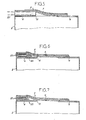
- FIG. 5 represents this bottom, seen in longitudinal section after introduction of a filling cannula (22).
- the introduction of the cannula allows filling through the slot (15) without the risk of the product escaping to the outside, or accumulating on the side of the closed end of the element. tubular.
- FIG. 6 represents a variant of the element (9) in which the tubular element comprises, on the side of its open end, a return (23) inwards, extending over its entire periphery.
- a sheet of flexible synthetic material (24) such as polyethylene which extends in the tubular element in the direction of the slot (15).
- the rim (23) acts as a non-return valve for the pulverulent material which could have accidentally passed through the slit (15) after closing it, and the sheet of synthetic material (24), which crumbles during the withdrawal of the cannula plays the role of a baffle further enhancing the effectiveness of the closure.
- the fold delimited by the rim (23) serves as a housing for a strip (25) of very sparse foam, of high compressibility and instantaneous extensibility, closing off all the conduits may result from folds of the sheets of paper or cardboard constituting the valve, and / or the presence of residual bagged product in the valve.
- the invention brings a great improvement to the existing technique by providing a bottom of a paper bag equipped with a single element having both the valve and “targette” functions preventing product flows. outwards, and constituting an internal reinforcement of the bottom sufficient to avoid the presence of an external reinforcement strip, added, of poor aesthetics.
Landscapes
- Engineering & Computer Science (AREA)
- Mechanical Engineering (AREA)
- Bag Frames (AREA)
- Making Paper Articles (AREA)
Claims (7)
Applications Claiming Priority (2)
| Application Number | Priority Date | Filing Date | Title |
|---|---|---|---|
| FR8502696A FR2577523B1 (fr) | 1985-02-18 | 1985-02-18 | Sac en papier dont un fond est equipe d'une valve de remplissage |
| FR8502696 | 1985-02-18 |
Publications (2)
| Publication Number | Publication Date |
|---|---|
| EP0193477A1 EP0193477A1 (de) | 1986-09-03 |
| EP0193477B1 true EP0193477B1 (de) | 1988-04-13 |
Family
ID=9316585
Family Applications (1)
| Application Number | Title | Priority Date | Filing Date |
|---|---|---|---|
| EP19860420041 Expired EP0193477B1 (de) | 1985-02-18 | 1986-02-12 | Papiersack, dessen Boden mit einem Füllventil versehen ist |
Country Status (4)
| Country | Link |
|---|---|
| EP (1) | EP0193477B1 (de) |
| DE (1) | DE3660122D1 (de) |
| ES (1) | ES292221Y (de) |
| FR (1) | FR2577523B1 (de) |
Families Citing this family (1)
| Publication number | Priority date | Publication date | Assignee | Title |
|---|---|---|---|---|
| CN109318536B (zh) * | 2018-11-18 | 2023-08-25 | 江苏宇驰包装股份有限公司 | 一种半自动纸袋糊底机 |
Family Cites Families (4)
| Publication number | Priority date | Publication date | Assignee | Title |
|---|---|---|---|---|
| US3894682A (en) * | 1972-07-07 | 1975-07-15 | Gilman Paper Company | Container with filling opening and closure means therefor |
| US4095736A (en) * | 1976-10-22 | 1978-06-20 | International Paper Company | Bag closure having valve sleeve |
| DE2652208A1 (de) * | 1976-11-16 | 1978-05-18 | Sachser Papierverarb | Ventilsack |
| DE3203187A1 (de) * | 1982-01-30 | 1983-08-11 | Nordenia-Kunststoffe Peter Mager Kg, 2841 Steinfeld | Fuell-ventil fuer einen ventil-sack |
-
1985
- 1985-02-18 FR FR8502696A patent/FR2577523B1/fr not_active Expired
-
1986
- 1986-02-07 ES ES1986292221U patent/ES292221Y/es not_active Expired
- 1986-02-12 EP EP19860420041 patent/EP0193477B1/de not_active Expired
- 1986-02-12 DE DE8686420041T patent/DE3660122D1/de not_active Expired
Also Published As
| Publication number | Publication date |
|---|---|
| DE3660122D1 (en) | 1988-05-19 |
| ES292221U (es) | 1986-06-01 |
| FR2577523B1 (fr) | 1987-10-30 |
| ES292221Y (es) | 1987-03-01 |
| FR2577523A1 (fr) | 1986-08-22 |
| EP0193477A1 (de) | 1986-09-03 |
Similar Documents
| Publication | Publication Date | Title |
|---|---|---|
| EP1089913A1 (de) | Schnell zusammenklappbare verpackung aus karton | |
| FR2727091A1 (fr) | Sac d'emballage | |
| FR2687128A1 (fr) | Flan de carton pour la realisation d'une barquette etanche, procede de mise en volume du flan et barquette etanche obtenue. | |
| EP1067054B1 (de) | Schachtel mit einem verstärkten Verschluss | |
| EP0452167A1 (de) | Tabakbeutel | |
| FR2816597A1 (fr) | Sac d'emballage | |
| EP1842785B1 (de) | Umschlag mit dichtem Verschluss | |
| EP1254846B1 (de) | Wiederverschliessbare flexible Verpackung | |
| EP0193477A1 (de) | Papiersack, dessen Boden mit einem Füllventil versehen ist | |
| FR2761342A1 (fr) | Emballage a remise a plat rapide | |
| FR2847234A1 (fr) | Sac a ouverture rapide et fermeture repositionnable | |
| EP1964786B1 (de) | Beutel, der für die Handbefüllung und den Verschluss von Hand geeignet ist | |
| FR2780704A1 (fr) | Sac refermable etanche | |
| FR2747108A1 (fr) | Emballage gonflable | |
| EP1702858B1 (de) | Verpackungsbeutel geeignet für mehrfaches Öffnen/Schliessen und Halten des Zwickels im gefalteten Zustand | |
| FR2884809A1 (fr) | Dispositif de protection et d'extraction d'un article | |
| FR2863252A1 (fr) | Sachet d'emballage, notamment pour couches de bebes, procede et machine de fabrication | |
| EP1261525A1 (de) | Abgedichtete schachtel mit fenster | |
| EP0571293B1 (de) | Polygonaler Schachtel aus Bogenmaterial und Zuschnitt zur Herstellung dieser Schachtel | |
| FR2688200A1 (fr) | Boite pliable a enveloppe souple interne a bec verseur refermable. | |
| FR2744427A3 (fr) | Conteneur en un materiau semi-rigide, pour le transport de materiaux divers | |
| FR2571701A1 (fr) | Boite utilisable notamment comme conditionnement de cigarettes | |
| FR2688764A1 (fr) | Conditionnement pour produit pateux. | |
| FR2713203A1 (fr) | Enveloppe de sécurité. | |
| MC1130A1 (fr) | Emballages,notamment en carton,ouverables par formation d'un volet |
Legal Events
| Date | Code | Title | Description |
|---|---|---|---|
| PUAI | Public reference made under article 153(3) epc to a published international application that has entered the european phase |
Free format text: ORIGINAL CODE: 0009012 |
|
| AK | Designated contracting states |
Kind code of ref document: A1 Designated state(s): BE CH DE GB IT LI LU NL |
|
| 17P | Request for examination filed |
Effective date: 19860804 |
|
| 17Q | First examination report despatched |
Effective date: 19871002 |
|
| ITF | It: translation for a ep patent filed | ||
| GRAA | (expected) grant |
Free format text: ORIGINAL CODE: 0009210 |
|
| AK | Designated contracting states |
Kind code of ref document: B1 Designated state(s): BE CH DE GB IT LI LU NL |
|
| GBT | Gb: translation of ep patent filed (gb section 77(6)(a)/1977) | ||
| REF | Corresponds to: |
Ref document number: 3660122 Country of ref document: DE Date of ref document: 19880519 |
|
| PGFP | Annual fee paid to national office [announced via postgrant information from national office to epo] |
Ref country code: CH Payment date: 19881227 Year of fee payment: 4 |
|
| PGFP | Annual fee paid to national office [announced via postgrant information from national office to epo] |
Ref country code: BE Payment date: 19890117 Year of fee payment: 4 |
|
| PLBE | No opposition filed within time limit |
Free format text: ORIGINAL CODE: 0009261 |
|
| STAA | Information on the status of an ep patent application or granted ep patent |
Free format text: STATUS: NO OPPOSITION FILED WITHIN TIME LIMIT |
|
| PGFP | Annual fee paid to national office [announced via postgrant information from national office to epo] |
Ref country code: DE Payment date: 19890221 Year of fee payment: 4 |
|
| PG25 | Lapsed in a contracting state [announced via postgrant information from national office to epo] |
Ref country code: LU Free format text: LAPSE BECAUSE OF NON-PAYMENT OF DUE FEES Effective date: 19890228 |
|
| PGFP | Annual fee paid to national office [announced via postgrant information from national office to epo] |
Ref country code: NL Payment date: 19890228 Year of fee payment: 4 |
|
| 26N | No opposition filed | ||
| PG25 | Lapsed in a contracting state [announced via postgrant information from national office to epo] |
Ref country code: GB Effective date: 19900212 |
|
| ITTA | It: last paid annual fee | ||
| PG25 | Lapsed in a contracting state [announced via postgrant information from national office to epo] |
Ref country code: LI Effective date: 19900228 Ref country code: CH Effective date: 19900228 Ref country code: BE Effective date: 19900228 |
|
| BERE | Be: lapsed |
Owner name: S.A. LEMBACEL Effective date: 19900228 |
|
| PG25 | Lapsed in a contracting state [announced via postgrant information from national office to epo] |
Ref country code: NL Effective date: 19900901 |
|
| GBPC | Gb: european patent ceased through non-payment of renewal fee | ||
| NLV4 | Nl: lapsed or anulled due to non-payment of the annual fee | ||
| REG | Reference to a national code |
Ref country code: CH Ref legal event code: PL |
|
| PG25 | Lapsed in a contracting state [announced via postgrant information from national office to epo] |
Ref country code: DE Effective date: 19901101 |
|
| PG25 | Lapsed in a contracting state [announced via postgrant information from national office to epo] |
Ref country code: IT Free format text: LAPSE BECAUSE OF NON-PAYMENT OF DUE FEES;WARNING: LAPSES OF ITALIAN PATENTS WITH EFFECTIVE DATE BEFORE 2007 MAY HAVE OCCURRED AT ANY TIME BEFORE 2007. THE CORRECT EFFECTIVE DATE MAY BE DIFFERENT FROM THE ONE RECORDED. Effective date: 20050212 |