EP0193497B1 - Wagon à déchargement par gravité à plusieurs compartiments ayant chacun leur mécanisme de déchargement - Google Patents
Wagon à déchargement par gravité à plusieurs compartiments ayant chacun leur mécanisme de déchargement Download PDFInfo
- Publication number
- EP0193497B1 EP0193497B1 EP86830029A EP86830029A EP0193497B1 EP 0193497 B1 EP0193497 B1 EP 0193497B1 EP 86830029 A EP86830029 A EP 86830029A EP 86830029 A EP86830029 A EP 86830029A EP 0193497 B1 EP0193497 B1 EP 0193497B1
- Authority
- EP
- European Patent Office
- Prior art keywords
- hatches
- car
- opening
- bilateral
- reduction gear
- Prior art date
- Legal status (The legal status is an assumption and is not a legal conclusion. Google has not performed a legal analysis and makes no representation as to the accuracy of the status listed.)
- Expired - Lifetime
Links
- 230000005484 gravity Effects 0.000 claims abstract description 18
- 230000002146 bilateral effect Effects 0.000 claims abstract description 15
- 230000005540 biological transmission Effects 0.000 claims abstract description 15
- 230000007246 mechanism Effects 0.000 claims description 15
- 230000008878 coupling Effects 0.000 claims description 8
- 238000010168 coupling process Methods 0.000 claims description 8
- 238000005859 coupling reaction Methods 0.000 claims description 8
- 230000009347 mechanical transmission Effects 0.000 claims description 7
- 230000011664 signaling Effects 0.000 claims description 7
- 230000002427 irreversible effect Effects 0.000 claims description 3
- 239000000463 material Substances 0.000 description 15
- 230000000694 effects Effects 0.000 description 3
- 230000000903 blocking effect Effects 0.000 description 1
- 239000003245 coal Substances 0.000 description 1
- 238000007599 discharging Methods 0.000 description 1
- -1 gravel Substances 0.000 description 1
- 238000012423 maintenance Methods 0.000 description 1
- 230000000284 resting effect Effects 0.000 description 1
- 239000004576 sand Substances 0.000 description 1
- 238000011144 upstream manufacturing Methods 0.000 description 1
Images




Classifications
-
- B—PERFORMING OPERATIONS; TRANSPORTING
- B61—RAILWAYS
- B61D—BODY DETAILS OR KINDS OF RAILWAY VEHICLES
- B61D7/00—Hopper cars
- B61D7/14—Adaptations of hopper elements to railways
- B61D7/16—Closure elements for discharge openings
- B61D7/24—Opening or closing means
- B61D7/26—Opening or closing means mechanical
Definitions
- Bulk cargos such as coal, gravel, sand cargos and the like are normally transported by rail in hopper cars; such cars are usually fitted with two separate bins for loading, while the discharge of the materials contained therein is effected by gravity through two large side hatches for each bin, wherein the hatches are opened by drive means into dump pits.
- a further requirement relates to the necessity, in case of improper functioning of the drive and transmission means, of avoiding the unintentional open-- ing of a pair of hatches which are out of the discharge area at the same time of, or instead of the hatches whose opening has been operated.
- a railway hopper car is known, corresponding to the first part of claim 1, with bilateral gravity discharge, comprising a container body having separate loading bins, each of these bins being provided with two openings on the opposite sides of the car, which may be closed by means of hatches hinged at their upper side, fitted with a plurality of locking hooks along the lower border; these hooks are fixedly carried by a shaft which is rotatively supported on the body of the car, which shaft can be rotated for unlocking the opening of the relative hatch by means of a mechanical transmission lever mechanism.
- the operation for unlocking the hatch is effected operating the mechanism at the corner of the car near the hatch to be opened; this means that the operator has to walk around the car to open consecutively all the hatches for discharging the material contained in the car.
- US-A 3 587 475 discloses a hopper car having doors which open in the bottom of the car, which are operated for the opening by means of selector mechanisms; these mechanism, however, are located on the two sides of the car, so that the operator must go around the car to set the selector of the doors to be opened; the doors are opened by pulling chains and are closed by gravity, without locking means, and no means is provided signalling the opening of the doors.
- a railway hopper car with bilateral gravity discharge comprising a container body formed by two or more consecutive, separate loading bins, each of these bins being provided with two openings on the opposite sides of the car, which may be closed by means of hatches hinged at their upper side, each of the hatches being fitted with a plurality of locking hooks along the lower border, the hooks being fixedly carried by a shaft which is rotatively supported on the body of the car; the shafts carrying the locking hooks relative to the hatches of each of the loading bins being arranged to rotate, at choice, for unlocking the opening of the hatches by means of mechanical transmission lever mechanisms, characterized in that the mechanisms comprise a reduction gear of the irreversible type which is hand-controlled by means of shanks accessible from ground which are directly connected to the reduction gear and, in addition, by means of a handwheel which may be connected to the reduction gear through a mechanical transmission comprising a select
- the lever mechanisms comprise a rocker keyed to the output or slow shaft of the reduction gear, at the ends of which there are hinged the extremities of two connecting rods which are, at the opposited extremities, hinged to two arms joined to the shafts carrying the locking hooks, wherein the rotation in one direction of the rocking lever is transmitted to the arms through the connecting rods, so as to cause rotation of the shafts in the sense suitable to disengage the locking hooks from the hatches, and in the opposite sense so as to cause the clamp of the hatches by means of the locking hooks.
- the axis of the rocker intersects the action axis of both the connecting rods or is laying beyond the axis, in the closing direction.
- the handwheel may be connected, through the selector and possible transmission shafts, to every reduction gear actuating the couple of hatches of each separate bin of the car; therefore, it is possible, by this way, to operate the opening of the selected couple of hatches by means of the handwheel itself.
- At least one of the locking hooks of each hatch is provided with a hindering foot which projects upwards, beyond the edge of the hooks, and interfers with the opening path of the hatches when the hooks are in a first rotation position apt to free the hatches, the foot being free to rotate in the sense of the opening and rotationally blocked in the opposite sense, being capable in such rotation position of the hooks of non hindering the hatches from a free opening and at the same time, however, hindering them from a total closure movement, whereas a further rotation of the shafts carrying the locking hooks bears the hindering foot, or feet, out of the movement path of the hatches, thereby making their closing possible.
- the means for driving the opening of the hatches consist of shaped arms fixedly joined to the shafts which carry the locking hooks, having at their ends rollers suitable to act against sliding blocks linked to the flanks of the hatches when the shafts are rotated in the opening sense beyond the unlocking point of the locking hooks and the hindering feet.
- the means signalling the opening of the hatches consist of two flags for each couple of hatches, which can rotate between a position enclosed in the side shape of the car and a position projecting from same; the flags being rotationally driven by connecting rods and cranks actuated by a staff hinged to a swivelling block which by gravity maintains the flags projecting out of the car shape, there being provided an arm joined rotationally to the rocker, suitable to act on the swivelling block when the rocker is rotated into the closing position, beyond the intersection position of its rotational axis with the action axes of the connecting rods.
- the selector is formed by a bilateral clutch which is rotationally joined, through a chain transmission or the like, to the handwheel and may be rotationally coupled, through a control lever, either with a corresponding clutch carried by a transmission shaft connected to a reduction gear relative to a couple of hatches located remote from the handwheel, or to a transmission shaft connected to a reduction gear relative to a couple of hatches located adjacent to the car head carrying the handwheel; the transmission shafts being independently supported by self-lubricating bushes carried by separate supporting elements and both being fixed to the car structure, so that the possible seizing of a bush may not bring the non selected shaft into rotation.
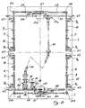
- a hopper car is usually formed by a body 1 subdivided into two bins 2, 3 separated by a wall 4. Inside of the loading bins there is provided a prismatic element 5, whose contour is dash- lined in the figure, having two oblique surfaces suitable to convey the contained material towards the couples of hatches 6, 7, relative to the front bin 2 and the back bin 3 respectively, with reference to the control platform 8 of the car.
- the hatches 6, 7 are hinged, adjacent to their upper side, to the body 1 of the car, as shown in figure 1 and their center of gravity is so provided that they may rest in closure position by effect of their own weight.
- the clamp of the hatches 6,7 in the closure position capable of standing the thrust of the material contained in the car is assured by a plurality of locking hooks 9,9a, supported by shafts 10, located below the lower border of the hatches, at the two opposite sides of the car.
- the opening of the hatches for enabling to discharge the material contained in one of the two bins 2,3 of the car, is caused by the thrust of the material itself which flows along the oblique flanks of the inner prismatic element 5 when the shafts 10, carrying the locking hooks 9,9a relative to the couple of hatches whose opening has been selected, are rotated of an angle sufficient to disengage the hooks 9,9a from the border of the hatches (see fig. 3 and 4).
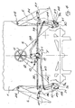
- Rotation of the shafts 10 is achieved by means of a drive group, as illustrated in figure 2 in schematic form and partially visible in transparence in figure 1, wherein the drive group is represented by thick lines whereas the external shape of the car is represented by thin lines; it comprises a handwheel 11 connected through a chain 12 to a selector 13 suitable to select the pair of hatches, in the front or back side, which are to be opened.
- the drive group is represented by thick lines whereas the external shape of the car is represented by thin lines; it comprises a handwheel 11 connected through a chain 12 to a selector 13 suitable to select the pair of hatches, in the front or back side, which are to be opened.
- the selector 13 may, in fact, connect the handwheel 11, through the gear wheels 15, 16 and a second transmission chain 17, to a shaft 18 that is in turn connected, through a bevel gears pair 19, to the input or quick shaft of a reduction gear 20 or to the cardanic transmission shaft 14, which is coupled, at the opposite end of the car, to a second bevel gears pair 19a and to a second reduction gear 20a.
- the output shaft of the reduction gears 20 and 20a carries a rocker 21, at the ends of which are connected the shaped connecting rods 22, 23 which are pivoted at their end on the arms 24 joined to the shafts 10 carrying the hooks 9, 9a.
- the locking hooks 9, arranged in middle position along the border of the hatches 6, 7 are shaped as shown in the left side of figure 3; the end locking hooks 9a are shaped as illustrated in the right portion of figure 3 and also in figures 4 and 5, and exhibit a projecting part which carries a pivot 28 about which the hindering foot 29 may swivel, being fitted with a counterweight 30 and resting against the stop pin 31.
- the hindering foot 29 does not represent an obstacle to the hatches movement as it is free to swivel about the pivot 28 under the thrust of the hatches themselves, as shown by dot-and-dash line in the right part of fig. 4; in the closing phase of the hatches, under the action of their own weight, when the thrust produced by the flowing material is lowering, the hindering feet 29 blocks the hatches themselves in partial opening position, as shown by a dot-and-dash line in the left part of fig.
- the input shafts to the reduction gears 20, 20a are besides connected with the shanks 32 for operation from earth, by which it is possible to carry out the operation of opening the hatches from earth; this operation is only possible when the selector 13 is in idle position, as the reduction gears 20, 20a are of the irreversible type, for example an endless screw, in order to prevent the handwheel 11 from being unvoluntarily brought into rotation by actuating the shanks 32, thus with danger of accident for a person casually staying on the platform in same moment.
- the opening of the hatches is associated with a signal constituted by flags 33 which are projecting from the car shape, as shown in fig. 1 and 3, when the lever mechanisms for driving the hatches have been removed from their safety block position.
- the closing position in fact, wherein the hooks 9, 9a lock the hatches, as shown in fig. 3, presents the rotation axis of the rocker 21 placed on the action axis of the connecting rods 22, 23 coupling the corresponding linking axes of the connecting rod itself with the rocker 21 and the arms 24.
- the signalling flags 33 are carried by the supports 34 swivelling about the pivots 35; the supports 34 are also fitted with levers 36, one of which is connected with a staff 37, hinged to a heavy block 38, which is swivelling about the pivot 39.
- a connecting rod 140 joins the ends of the levers 36, thus enabling a joined movement of the two flags 33 at both sides of the car.
- the shafts 10 carry, in correspondence to the extremities of the hatches 6, 7, the shaped arms 43, having an end roller 44 suitable to act against the sliding blocks 45 linked to the flanks of the hatches 6, 7.
- the shaft 55 is carried by the bush support 56 and is connected at its end with the cardanic shaft 14.
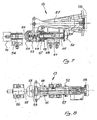
- the bilateral coupling element 53 may be brought into the position of engagement with the frontal coupling 46 or with the frontal coupling 54, or maintained in a middle position, or "idle” position, through the lever 57 having three fixed stop positions which may be disengaged through the knob 58, as shown by dash-and-dot line in figure 7.
- the selector 13 keeps the shaft 55 and the gear wheel 15 separated and independent; in this way, it is not possible that, in case of seizing of the self-lubricating bushes supporting the rotary elements, a non selected couple of hatches is also brought into rotation, as it would occur if the gear 15 were supported by bushes placed directly on the shaft 51, in case of seizing and blocking of the bushes.
- the opening limiting rods 26, hinged at one end of the car structure, present a curvilinear shape; such a shape serves to establish a free space between the car wall and the surface of the rod 26 which is substantially larger than the maximum size of the transported material; this to the aim of assuring that possible material deposited on the surface of the rods may not remain closed, during unloading, between the same and the car, thus hindering a complete closing movement of the hatches.
- a curvilinear conformation for the same above mentioned purpose, is provided for the arms 24 too, which, as they are also located in the area subject to material flowing, have not to be in condition of holding back some material against the car wall, what would hinder the hooks 9, 9a from their complete closing movement causing the clamp of the hatches.
- the opening mechanism according to the present invention proves to be especially safe and reliable, besides economically convenient, since the transmissions and selection of the hatches to be opened are carried out at high speed, upstream to the reduction gears and consequently with low driving torques.
- the car structure may be built according to the known art; it has, therefore, not to be described here in detail.
Landscapes
- Engineering & Computer Science (AREA)
- Transportation (AREA)
- Mechanical Engineering (AREA)
- Filling Or Emptying Of Bunkers, Hoppers, And Tanks (AREA)
- Feeding Of Articles To Conveyors (AREA)
- Warehouses Or Storage Devices (AREA)
- Braking Arrangements (AREA)
- Loading Or Unloading Of Vehicles (AREA)
- Power-Operated Mechanisms For Wings (AREA)
Claims (8)
Priority Applications (1)
| Application Number | Priority Date | Filing Date | Title |
|---|---|---|---|
| AT86830029T ATE53354T1 (de) | 1985-02-12 | 1986-02-11 | Eisenbahn-trichterwagen mit mehreren behaeltern mit je einer entladevorrichtung. |
Applications Claiming Priority (2)
| Application Number | Priority Date | Filing Date | Title |
|---|---|---|---|
| IT19475/85A IT1183245B (it) | 1985-02-12 | 1985-02-12 | Carro ferrcviario a tramoggia a piu'scomparti con comando di scarico separato |
| IT1947585 | 1985-02-12 |
Publications (3)
| Publication Number | Publication Date |
|---|---|
| EP0193497A2 EP0193497A2 (fr) | 1986-09-03 |
| EP0193497A3 EP0193497A3 (en) | 1987-09-30 |
| EP0193497B1 true EP0193497B1 (fr) | 1990-06-06 |
Family
ID=11158333
Family Applications (1)
| Application Number | Title | Priority Date | Filing Date |
|---|---|---|---|
| EP86830029A Expired - Lifetime EP0193497B1 (fr) | 1985-02-12 | 1986-02-11 | Wagon à déchargement par gravité à plusieurs compartiments ayant chacun leur mécanisme de déchargement |
Country Status (5)
| Country | Link |
|---|---|
| EP (1) | EP0193497B1 (fr) |
| AT (1) | ATE53354T1 (fr) |
| DE (1) | DE3671729D1 (fr) |
| ES (1) | ES8700615A1 (fr) |
| IT (1) | IT1183245B (fr) |
Families Citing this family (3)
| Publication number | Priority date | Publication date | Assignee | Title |
|---|---|---|---|---|
| FI92665C (fi) * | 1992-11-04 | 1994-12-27 | Transtech Ltd Oy | Katteensiirtomekanismi |
| CN103496373B (zh) * | 2013-09-29 | 2017-01-04 | 中车长江车辆有限公司 | 两用漏斗车 |
| CN111942413B (zh) * | 2020-08-13 | 2023-05-23 | 中车齐齐哈尔车辆有限公司 | 石砟车的漏斗底门的手动启闭机构及石砟车 |
Family Cites Families (5)
| Publication number | Priority date | Publication date | Assignee | Title |
|---|---|---|---|---|
| DE160913C (fr) * | 1903-05-23 | |||
| FR529809A (fr) * | 1921-01-14 | 1921-12-07 | Wagon trémie à déchargement automatique bi-latéral à portes à guichet | |
| DE491984C (de) * | 1928-03-06 | 1930-02-19 | Linke Hofmann Busch Werke Akt | Umschaltbare Kupplung fuer die Drehrichtungsaenderung von Antriebswellen zur Bedienung von Selbstentladerklappen oder Kastenkippern |
| DE2452047C2 (de) * | 1974-11-02 | 1976-12-16 | Waggon Union Gmbh | Klappenverschluss fuer eisenbahngueterwagen |
| US3587475A (en) * | 1968-12-27 | 1971-06-28 | Eduardo M Damy | Selectively actuated hopper car doors |
-
1985
- 1985-02-12 IT IT19475/85A patent/IT1183245B/it active
-
1986
- 1986-02-10 ES ES551781A patent/ES8700615A1/es not_active Expired
- 1986-02-11 DE DE8686830029T patent/DE3671729D1/de not_active Expired - Lifetime
- 1986-02-11 EP EP86830029A patent/EP0193497B1/fr not_active Expired - Lifetime
- 1986-02-11 AT AT86830029T patent/ATE53354T1/de not_active IP Right Cessation
Also Published As
| Publication number | Publication date |
|---|---|
| ES551781A0 (es) | 1986-11-16 |
| EP0193497A3 (en) | 1987-09-30 |
| IT8519475A0 (it) | 1985-02-12 |
| DE3671729D1 (de) | 1990-07-12 |
| EP0193497A2 (fr) | 1986-09-03 |
| IT1183245B (it) | 1987-10-15 |
| ES8700615A1 (es) | 1986-11-16 |
| ATE53354T1 (de) | 1990-06-15 |
Similar Documents
| Publication | Publication Date | Title |
|---|---|---|
| US3187684A (en) | Rapid discharge hopper car | |
| US2258988A (en) | Refuse truck | |
| US3396675A (en) | Dual hopper outlet closure structure | |
| US5261333A (en) | Automated ballast door mechanism | |
| US6405658B1 (en) | Manual discharge door operating system for a hopper railcar | |
| CA1070564A (fr) | Mecanisme de verrouillage d'obturateur de wagon-tremie | |
| EP0193497A2 (fr) | Wagon à déchargement par gravité à plusieurs compartiments ayant chacun leur mécanisme de déchargement | |
| US3314558A (en) | System for automatically operating discharge doors of railway cars | |
| US1763560A (en) | Loading apparatus | |
| US3459316A (en) | Means for automatically operating bottom hopper discharge doors during travel of railway cars | |
| MXPA05002137A (es) | Cierre de puerta de vagon ferroviario. | |
| US3515076A (en) | Manual or trackway cam hopper car door operating mechanism | |
| US4213725A (en) | Double locking door latch mechanism for railway hopper cars | |
| US2891487A (en) | Hopper door locking mechanism | |
| US3483830A (en) | Selectively actuate clutch controlled toggle actuated railway hopper car doors | |
| EP0054051B1 (fr) | Garage a bicyclettes | |
| CN209274594U (zh) | 一种漏斗车侧门开闭系统 | |
| US4629386A (en) | Railroad hopper car door opener | |
| US2741194A (en) | Operating mechanism for dumping door | |
| AU741224B2 (en) | Railway wagon discharge system | |
| US3474920A (en) | Operating mechanism for a vehicle discharge means | |
| CN119898633B (en) | Oil drum turning device | |
| US3255713A (en) | Dumping railway car | |
| JPH07250530A (ja) | ローンモアのキャッチャボックス | |
| SU1678674A1 (ru) | Устройство дл открывани и закрывани крышек разгрузочных люков бункерного вагона |
Legal Events
| Date | Code | Title | Description |
|---|---|---|---|
| PUAI | Public reference made under article 153(3) epc to a published international application that has entered the european phase |
Free format text: ORIGINAL CODE: 0009012 |
|
| AK | Designated contracting states |
Kind code of ref document: A2 Designated state(s): AT BE CH DE FR GB LI |
|
| 17P | Request for examination filed |
Effective date: 19861103 |
|
| PUAL | Search report despatched |
Free format text: ORIGINAL CODE: 0009013 |
|
| AK | Designated contracting states |
Kind code of ref document: A3 Designated state(s): AT BE CH DE FR GB LI |
|
| 17Q | First examination report despatched |
Effective date: 19880928 |
|
| GRAA | (expected) grant |
Free format text: ORIGINAL CODE: 0009210 |
|
| AK | Designated contracting states |
Kind code of ref document: B1 Designated state(s): AT BE CH DE FR GB LI |
|
| REF | Corresponds to: |
Ref document number: 53354 Country of ref document: AT Date of ref document: 19900615 Kind code of ref document: T |
|
| REF | Corresponds to: |
Ref document number: 3671729 Country of ref document: DE Date of ref document: 19900712 |
|
| ET | Fr: translation filed | ||
| PG25 | Lapsed in a contracting state [announced via postgrant information from national office to epo] |
Ref country code: AT Effective date: 19910211 |
|
| PGFP | Annual fee paid to national office [announced via postgrant information from national office to epo] |
Ref country code: GB Payment date: 19910211 Year of fee payment: 6 |
|
| PG25 | Lapsed in a contracting state [announced via postgrant information from national office to epo] |
Ref country code: LI Effective date: 19910228 Ref country code: CH Effective date: 19910228 Ref country code: BE Effective date: 19910228 |
|
| PLBE | No opposition filed within time limit |
Free format text: ORIGINAL CODE: 0009261 |
|
| STAA | Information on the status of an ep patent application or granted ep patent |
Free format text: STATUS: NO OPPOSITION FILED WITHIN TIME LIMIT |
|
| 26N | No opposition filed | ||
| PG25 | Lapsed in a contracting state [announced via postgrant information from national office to epo] |
Ref country code: FR Effective date: 19911031 |
|
| REG | Reference to a national code |
Ref country code: CH Ref legal event code: PL |
|
| PG25 | Lapsed in a contracting state [announced via postgrant information from national office to epo] |
Ref country code: DE Effective date: 19911101 |
|
| REG | Reference to a national code |
Ref country code: FR Ref legal event code: ST |
|
| PG25 | Lapsed in a contracting state [announced via postgrant information from national office to epo] |
Ref country code: GB Effective date: 19920211 |
|
| GBPC | Gb: european patent ceased through non-payment of renewal fee |