EP0193613A1 - Generateur de signaux d'affichage - Google Patents
Generateur de signaux d'affichage Download PDFInfo
- Publication number
- EP0193613A1 EP0193613A1 EP85904286A EP85904286A EP0193613A1 EP 0193613 A1 EP0193613 A1 EP 0193613A1 EP 85904286 A EP85904286 A EP 85904286A EP 85904286 A EP85904286 A EP 85904286A EP 0193613 A1 EP0193613 A1 EP 0193613A1
- Authority
- EP
- European Patent Office
- Prior art keywords
- signal
- pulse
- analog
- digital
- frequency
- Prior art date
- Legal status (The legal status is an assumption and is not a legal conclusion. Google has not performed a legal analysis and makes no representation as to the accuracy of the status listed.)
- Withdrawn
Links
Images

Classifications
-
- G—PHYSICS
- G01—MEASURING; TESTING
- G01R—MEASURING ELECTRIC VARIABLES; MEASURING MAGNETIC VARIABLES
- G01R13/00—Arrangements for displaying electric variables or waveforms
-
- G—PHYSICS
- G01—MEASURING; TESTING
- G01D—MEASURING NOT SPECIALLY ADAPTED FOR A SPECIFIC VARIABLE; ARRANGEMENTS FOR MEASURING TWO OR MORE VARIABLES NOT COVERED IN A SINGLE OTHER SUBCLASS; TARIFF METERING APPARATUS; MEASURING OR TESTING NOT OTHERWISE PROVIDED FOR
- G01D7/00—Indicating measured values
- G01D7/002—Indicating measured values giving both analog and numerical indication
Definitions
- the present invention relates to a display signal generator device connected to an analog or digital display unit for generating a display pulse train signal regulated to display on any of analog and digital display units.
- a conventional display signal generator device or this type needs to convert a certain signal into a signal of analog amount in case of displaying the certain signal on a display unit if the display unit is of an analog display type, while the display signal generator device necessitates to convert a certain signal into a signal of digital amount in case of displaying the certain signal on the display unit if the display unit is of a digital display type.
- the conventional display signal generator device requires a unit for processing the signal to be displayed corresponding to the format of the display unit to analog or digital amount.
- the conventional device complicates the constitution or needs to have two types of units for analog and digital, and has a problem of uneconomy.
- the present invention has for its object to provide a display signal generator device which can convert a signal to be displayed into a frequency signal having a pulse repetition period corresponding to the content of the signal, set the width of each pulse of this frequency signal to a predetermined value to thereby generate a pulse train signal capable of being applied to the display unit even if the display unit is of analog or digital type.
- a display signal generator device which comprises: a converter for converting a digital data representing the level of a signal to be displayed into a frequency signal having a pulse train, and a pulse generator which outputs a signal for a digital display unit from the converter, has a predetermined pulse width in the signal of the converter and outputs a signal for an analog display unit from the pulse generator.
- the signal for the digital display unit has a pulse repetition period corresponding to the content of the signal to be displayed, and is digitally displayed by an ordinary digital display unit using a counter, while the signal for the analog display unit has a value corresponding to the content of the signal to be displayed with the average value of the signal, and the analog display unit such as a meter is analog-displayed in response to the average value.
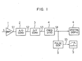
- Fig. 1 is a block diagram of a display signal generator device according to one embodiment of the present invention
- Fig. 2 is a waveform diagram showing the operation of the display signal generator device shown in Fig. 1
- Fig. 3 is a block diagram of a display signal generator device according to another embodiment of the invention.
- Fig. 1 is a block diagram showing an embodiment of a display signal generator device according to the present invention.
- Numeral 1 designates an amplifier, which amplifies an input signal S having a certain analog amount.
- Numeral 2 designates an analog-to-digital (A/D) converter for analog-to-digital converting a signal Sl outputted from the amplifier 1
- numeral 3 designates a frequency (D/F) converter having a rate multiplier for generating a signal S3 having a pulse train from a signal S2 of the A/D converter 2
- numeral 4 designates a frequency divider for suitably dividing the frequency of the signal S3 and supplying a signal S4 to a digital display unit 6
- numeral 5 designates a pulse generator which is, for example, a monostable multivibrator, inputs the signal S4, applies a pulse width T 0 to the pulse and supplies a signal S5 to an analog display unit 7 such as, for example, a movable coil type ammeter.
- the input signal S having a certain analog amount is amplified by the amplifier 1 to become the signal Sl, and the signal S1 is inputted to the A/D converter 2.
- the converter 2 analog-to-digital converts the signal SI and outputs a digital signal S2 (not shown) having data of the content of analog level of the signal S2.
- the D/F converter 3 generates a signal S3 having a frequency corresponding to the content of the digital signal S2.
- the digital amount is converted to the pulse repetition period, i.e., frequency information.
- the signal S3 has a pulse waveform as shown in Fig. 2, and is divided by the frequency divider 4 to produce the signal S4.
- the signal S4 corresponds in frequency to the analog amount of the input signal S, is inputted to the digital display unit 6, and digitally displayed, for example, by numeric characters.
- the signal S4 is inputted to the pulse generator 5 of a monostable multivibrator, becomes a signal S5 of a pulse train having a pulse width TO and pulse repetition periods T 1 , T 2 and T 3 , and is supplied to the analog display unit 7.
- the analog display unit 7 for example, employs a movable coil type ammeter (DC 1mA). Since this has an inertia, the display unit 7 does not display in response to the pulse waveform of the signal S5, but displays in response to the average value of the signal S5.
- DC 1mA movable coil type ammeter
- the average value of the signals S5 corresponds to the analog amount of the input signal S.
- the signal becomes a pulse train signal having a period T 1 and a pulse width T 0 for the voltage E 1 of the signal S1, and similarly becomes a pulse train signal having a period T 2 for the voltage E 2 and a voltage E 3 for the voltage E 3 .
- the frequency divider 4 and the pulse generator 5 may be respectively selected in the frequency division ratio and the pulse width.
- the pulse generator 5 may be a counter which is constructed to count clock signals from the varying point of the pulse signal S4 inputted only for the time of the pulse width TO.
- Fig. 3 shows another embodiment of the present invention, and, as apparent from Fig. 2, the input terminal of the digital unit 6 is provided at the output of the pulse generator 5 so as to receive the signal S5 to digitally count.
- the display signal generator device is constructed to output a signal for a converter digital display unit for converting the digital data representing the level of the signal to be displayed into a frequency signal having a pulse train, and to output a signal for an analog display unit from the pulse generator having a predetermined pulse width for the signal of the converter. Therefore, even if the display unit is of analog type or digital type, the corresponding signal can be produced by a simple circuit.
Landscapes
- Physics & Mathematics (AREA)
- General Physics & Mathematics (AREA)
- Analogue/Digital Conversion (AREA)
- Indicating Measured Values (AREA)
- Arrangements For Transmission Of Measured Signals (AREA)
- Control Of Indicators Other Than Cathode Ray Tubes (AREA)
- Indication And Recording Devices For Special Purposes And Tariff Metering Devices (AREA)
- Measuring Frequencies, Analyzing Spectra (AREA)
Abstract
Un générateur de signaux d'affichage produit des signaux qui peuvent être utilisés à la fois pour un dispositif d'affichage analogique (7) et pour un dispositif d'affichage numérique (6) pour indiquer la fréquence de sortie de l'inverseur. A cet effet, la largeur d'impulsion des signaux numériques est maintenue constante, et on fait varier le cycle de répétition de l'impulsion proportionnellement à la quantité analogique des signaux d'entrée. Par conséquent, on obtient des signaux qui peuvent être communément utilisés tant pour des applications numériques que pour des applications analogiques, la valeur moyenne des signaux d'impulsion variant proportionnellement à la fréquence. Etant donné que la largeur d'impulsion est maintenue constante, seul un multivibrateur monostable est nécessaire, ce qui permet de construire un générateur de signaux d'affichage à des coûts réduits.
Applications Claiming Priority (2)
| Application Number | Priority Date | Filing Date | Title |
|---|---|---|---|
| JP181699/84 | 1984-08-31 | ||
| JP59181699A JPS6159486A (ja) | 1984-08-31 | 1984-08-31 | 表示信号発生装置 |
Publications (2)
| Publication Number | Publication Date |
|---|---|
| EP0193613A1 true EP0193613A1 (fr) | 1986-09-10 |
| EP0193613A4 EP0193613A4 (fr) | 1989-02-06 |
Family
ID=16105312
Family Applications (1)
| Application Number | Title | Priority Date | Filing Date |
|---|---|---|---|
| EP19850904286 Withdrawn EP0193613A4 (fr) | 1984-08-31 | 1985-08-30 | Generateur de signaux d'affichage. |
Country Status (4)
| Country | Link |
|---|---|
| US (1) | US4743843A (fr) |
| EP (1) | EP0193613A4 (fr) |
| JP (1) | JPS6159486A (fr) |
| WO (1) | WO1986001594A1 (fr) |
Families Citing this family (5)
| Publication number | Priority date | Publication date | Assignee | Title |
|---|---|---|---|---|
| US4862074A (en) * | 1988-10-14 | 1989-08-29 | Westinghouse Electric Corp. | Polyphase volt-hour indicating circuit |
| USD352716S (en) | 1992-12-15 | 1994-11-22 | Sony Corporation | Display signal generator |
| US6011538A (en) * | 1997-06-18 | 2000-01-04 | Paradise Electronics, Inc. | Method and apparatus for displaying images when an analog-to-digital converter in a digital display unit is unable to sample an analog display signal at a desired high sampling frequency |
| US20050110749A1 (en) * | 2003-11-25 | 2005-05-26 | Precisionwave Corporation | Signal generator with display |
| KR100772547B1 (ko) * | 2006-08-31 | 2007-11-02 | 주식회사 하이닉스반도체 | 반도체 장치 및 그의 테스트 방법 |
Family Cites Families (13)
| Publication number | Priority date | Publication date | Assignee | Title |
|---|---|---|---|---|
| US3689835A (en) * | 1970-09-10 | 1972-09-05 | Veeder Industries Inc | Analog/digital meter having front indicator means overlying a rear indicator means |
| AU460257B2 (en) * | 1970-10-15 | 1975-04-24 | Master Instruments Pty. Ltd | Improvements in and relating to data transmission |
| JPS4887873A (fr) * | 1972-02-21 | 1973-11-17 | ||
| US3794916A (en) * | 1972-03-09 | 1974-02-26 | Hewlett Packard Co | Digital voltmeter |
| JPS5651302B2 (fr) * | 1974-03-02 | 1981-12-04 | ||
| JPS5937733Y2 (ja) * | 1975-12-23 | 1984-10-19 | 宗一郎 安永 | デイジタル・アナログ計器 |
| JPS5427674A (en) * | 1977-07-30 | 1979-03-01 | Fujitsu Ltd | Analog indicator circuit for digital value |
| JPS5918365Y2 (ja) * | 1978-10-05 | 1984-05-28 | 株式会社三和電気製作所 | アナログ.デジタル両表示テスタ |
| JPS5553461A (en) * | 1978-10-16 | 1980-04-18 | Fujitsu Ltd | Manufacture of semiconductor device |
| JPS55113969U (fr) * | 1979-01-18 | 1980-08-11 | ||
| JPS55113969A (en) * | 1979-02-26 | 1980-09-02 | Toshiba Corp | Malfunction detector for diode |
| US4415855A (en) * | 1979-04-12 | 1983-11-15 | The Lewis Engineering Company | Combination analog-digital indicator |
| DE2924093A1 (de) * | 1979-06-15 | 1981-01-08 | Bosch Gmbh Robert | Induktiver differentialweggeber |
-
1984
- 1984-08-31 JP JP59181699A patent/JPS6159486A/ja active Granted
-
1985
- 1985-08-30 US US06/860,191 patent/US4743843A/en not_active Expired - Fee Related
- 1985-08-30 EP EP19850904286 patent/EP0193613A4/fr not_active Withdrawn
- 1985-08-30 WO PCT/JP1985/000478 patent/WO1986001594A1/fr not_active Ceased
Also Published As
| Publication number | Publication date |
|---|---|
| WO1986001594A1 (fr) | 1986-03-13 |
| JPH0373034B2 (fr) | 1991-11-20 |
| EP0193613A4 (fr) | 1989-02-06 |
| JPS6159486A (ja) | 1986-03-26 |
| US4743843A (en) | 1988-05-10 |
Similar Documents
| Publication | Publication Date | Title |
|---|---|---|
| US4380733A (en) | Frequency and speed display device | |
| US4486707A (en) | Gain switching device with reduced error for watt meter | |
| EP0240102A2 (fr) | Appareil de mesure de puissance avec autocontrôle | |
| US4920312A (en) | Multiplier | |
| US4743843A (en) | Display signal generator device | |
| US4784001A (en) | Magnetic flowmeter with isolation amplifier and ranging circuit therefor and method | |
| US4199817A (en) | Digital averager | |
| GB2042837A (en) | Digital voltmeter with waveform display | |
| GB2066626A (en) | Voltage converter | |
| US4672236A (en) | Voltage-to-frequency converter circuit | |
| US4534004A (en) | Apparatus and method for determining signal parameters of periodic square wave signals | |
| US3977484A (en) | Electronic scale apparatus with dead weight calculating means | |
| JP3026533B2 (ja) | 無効電力量計 | |
| JPS6318725A (ja) | 低レベル電圧−パルス変換器 | |
| JPH0633427Y2 (ja) | ジッタ測定装置 | |
| JP2668396B2 (ja) | データ表示装置 | |
| US4110747A (en) | Apparatus for producing analog-to-digital conversions | |
| JPH0348540Y2 (fr) | ||
| JP3124990B2 (ja) | 計測値−周波数変換装置 | |
| CN1005651B (zh) | 显示信号发生器装置 | |
| JPS62148863A (ja) | 電子式電力量計 | |
| SU834738A1 (ru) | Устройство дл отображени информацииНА эКРАНЕ элЕКТРОННОлучЕВОй ТРубКи | |
| JP2698489B2 (ja) | 電力量計 | |
| JPH043276Y2 (fr) | ||
| SU676937A1 (ru) | Электроизмерительный прибор |
Legal Events
| Date | Code | Title | Description |
|---|---|---|---|
| PUAI | Public reference made under article 153(3) epc to a published international application that has entered the european phase |
Free format text: ORIGINAL CODE: 0009012 |
|
| 17P | Request for examination filed |
Effective date: 19860428 |
|
| AK | Designated contracting states |
Kind code of ref document: A1 Designated state(s): DE GB |
|
| A4 | Supplementary search report drawn up and despatched |
Effective date: 19890206 |
|
| 17Q | First examination report despatched |
Effective date: 19900823 |
|
| STAA | Information on the status of an ep patent application or granted ep patent |
Free format text: STATUS: THE APPLICATION IS DEEMED TO BE WITHDRAWN |
|
| 18D | Application deemed to be withdrawn |
Effective date: 19920110 |
|
| RIN1 | Information on inventor provided before grant (corrected) |
Inventor name: TADA, HIDEAKIMITSUBISHI DENKI KABUSHIKI KAISHA |