EP0193627B1 - Vorrichtung zum reproduzierbaren Ausrichten eines Kiefermodells - Google Patents
Vorrichtung zum reproduzierbaren Ausrichten eines Kiefermodells Download PDFInfo
- Publication number
- EP0193627B1 EP0193627B1 EP85102383A EP85102383A EP0193627B1 EP 0193627 B1 EP0193627 B1 EP 0193627B1 EP 85102383 A EP85102383 A EP 85102383A EP 85102383 A EP85102383 A EP 85102383A EP 0193627 B1 EP0193627 B1 EP 0193627B1
- Authority
- EP
- European Patent Office
- Prior art keywords
- model
- runner
- complementary part
- base
- arcuate
- Prior art date
- Legal status (The legal status is an assumption and is not a legal conclusion. Google has not performed a legal analysis and makes no representation as to the accuracy of the status listed.)
- Expired
Links
- 230000000295 complement effect Effects 0.000 claims abstract description 15
- 238000003780 insertion Methods 0.000 description 2
- 230000037431 insertion Effects 0.000 description 2
- 239000004568 cement Substances 0.000 description 1
Images

Classifications
-
- A—HUMAN NECESSITIES
- A61—MEDICAL OR VETERINARY SCIENCE; HYGIENE
- A61C—DENTISTRY; APPARATUS OR METHODS FOR ORAL OR DENTAL HYGIENE
- A61C13/00—Dental prostheses; Making same
- A61C13/0027—Base for holding castings
Definitions
- the invention relates to a device for the reproducible alignment of a jaw model, for example to a general reference axis and / or the tooth axes of individual tooth stumps of the jaw model to the general reference axis, on the base of which a tiltable model table with receiving plate and model holder, in which the jaw model can be inserted, Can be rotated through 360 °, near their contact surfaces on the model table and on the base supporting them are provided with markings and the axis for the arcuate tilting movement of the model table is arranged outside the device.
- dental prostheses For the production of dental prostheses, it is known in dental prosthetics to shape the naturally grown teeth into tooth stump pillars and to cement an inner crown with conical outer surfaces onto each of them. The denture can then be placed on the pillars with inner crowns. It is first necessary that the dental prosthesis has a common insertion direction with which it can be pushed onto all pillars provided with conical crowns. However, since the individual tooth stumps have different angles of inclination in different directions, the cone crowns must be shaped appropriately, taking advantage of the cone tolerance and taking into account the common direction of insertion.
- a known device for aligning the tooth longitudinal axes of individual tooth stumps of a tooth model (DE-C-3 306 056)
- at least two rotating bodies lying one on top of the other and rotatable relative to one another are provided with annular bearing surfaces, the model table being arranged on the upper bearing surface of the upper rotating body and being rotatable through 360 ° is, at least one contact surface of at least one rotating body extends obliquely to the axis of rotation and circumferential markings are arranged on the outer sides of the rotating body such that a reproducible setting is possible.
- Model tables are also known in which either the model holder has a ball joint or the mounting plate can be tilted in two directions by a horizontal tilt axis offset by 90 °.
- a receiving plate is arranged on a carrier with a spherical zone-shaped outer wall.
- the carrier is rotatable about its central axis and tiltable in a cylindrical frame with a correspondingly shaped upper edge.
- the object of the invention is therefore to provide a device of the type mentioned, which can be used both for the reproducible alignment of a jaw model on a general reference axis and the tooth axes of individual tooth stumps of the jaw model on the reference axis, its structure being simple and easy to read Setting results and quick re-setting of previously determined changes in position is guaranteed.
- an arcuate runner is arranged on the underside of the receiving plate, which can be placed on a complementary part of the base with a correspondingly curved surface and along the surface of the complementary part forming the path for the runner , wherein the markings are arranged on at least one longitudinal side surface of the runner and on the complementary part.
- one of the runners has a longitudinal groove into which a rib of the Complementary part protrudes.
- the position of the common reference axis and the different tooth axes of a tooth model can be reproduced quickly and reliably, as a result of which the storage of such devices, in particular in larger dental laboratories, can be significantly reduced.
- a convex-arch-shaped runner 2 is arranged on the underside of a receiving plate 1 and has a longitudinal groove 3.
- a model holder 4 is inserted on the mounting plate 1, which can be rotated through 360 ° on the mounting plate 1 and can be fixed on the mounting plate 1 with the aid of an adjusting screw 9.
- the receiving plate 1 is placed with its runner 2 on a complementary part 5 serving as a base 5 with a rib 10 and displaceable along the runner 6 such that the receiving plate 1 is tilted from a position according to FIG. 1 into a position according to FIG. 3.
- a complementary part 5 serving as a base 5 with a rib 10 and displaceable along the runner 6 such that the receiving plate 1 is tilted from a position according to FIG. 1 into a position according to FIG. 3.
- the receiving plate 1 with the jaw model fixed thereon is caused to tilt in that the runner 2 is displaced along the runway 6. Since the runner has only a slight curvature, the runner describes the section of a relatively large circular arc, the axis of which lies outside the device.
- the jaw model can be brought into the desired tilt position both for determining the general reference axis and the individual tooth stumps for determining the deviations of the longitudinal axes of the tooth from the general reference axis, and the determined changes in position can be reproduced again quickly and very precisely. It is also possible to place two devices on top of one another in order to determine the general reference axis with the aid of one device and to align the axes of the tooth stumps with the general reference axis with the aid of the other device.
- Devices with different curvatures can also be used for the tilting movement.
- Devices with different cam tracks are possible.
Landscapes
- Health & Medical Sciences (AREA)
- General Health & Medical Sciences (AREA)
- Dentistry (AREA)
- Epidemiology (AREA)
- Life Sciences & Earth Sciences (AREA)
- Animal Behavior & Ethology (AREA)
- Oral & Maxillofacial Surgery (AREA)
- Public Health (AREA)
- Veterinary Medicine (AREA)
- Dental Tools And Instruments Or Auxiliary Dental Instruments (AREA)
- Dental Prosthetics (AREA)
- Load-Engaging Elements For Cranes (AREA)
- Devices For Post-Treatments, Processing, Supply, Discharge, And Other Processes (AREA)
- Instructional Devices (AREA)
Description
- Die Erfindung betrifft eine Vorrichtung zum reproduzierbaren Ausrichten eines Kiefermodells, zum Beispiel auf eine allgemeine Bezugsachse und/oder der Zahnachsen einzelner Zahnstümpfe des Kiefermodells auf die allgemeine Bezugsachse, auf deren Sockel ein kippbarer Modelltisch mit Aufnahmeteller und Modellhalterung, in die das Kiefermodell fixierbar einsetzbar ist, um 360° drehbar aufsetzbar ist, wobei nahe ihrer Berührungsflächen am Modelltisch und an dem diesen tragenden Sockel einander zugeordnete Markierungen vorgesehen sind und wobei die Achse für die bogenförmige Kippbewegung des Modelltisches außerhalb der Vorrichtung angeordnet ist.
- Zur Herstellung von Zahnprothesen ist es in der Zahnprothetik bekannt, die natürlich gewachsenen Zähne zu Zahnstumpfpfeilern auszuformen und auf diese jeweils eine Innenkrone mit konischen Außenflächen aufzuzementieren. Die Zahnprothese läßt sich dann auf die mit Innenkronen versehenen Pfeiler aufsetzen. Dabei ist es zunächst erforderlich, daß die Zahnprothese eine gemeinsame Einschubrichtung aufweist, mit der sie auf alle mit Konuskronen versehenen Pfeiler aufschiebbar ist. Da jedoch die einzelnen Zahnstümpfe unterschiedliche Neigungswinkel in unterschiedlichen Richtungen haben, müssen die Konuskronen unter Ausnutzung der Konustoleranz und unter Berücksichtigung der gemeinsamen Einschubrichtung passend ausgeformt werden.
- Es ist z. B. für die Herstellung von Zahnersatz mit Konuskronen notwendig, ein den natürlichen Zahnstellungen entsprechendes Zahnmodell auf eine gemeinsame Bezugsachse auszurichten, wobei das Zahnmodell bis zu ca. 25° neigbar sein muß. Es ist ferner notwendig, die Abweichungen der Zahnlängsachsen aller Zahnstümpfe in Bezug auf die Bezugsachse zu bestimmen, wobei eine Winkelabweichung bis zu 6° gegeben sein kann. Sowohl die Lage der allgemeinen Bezugsachse als auch die Abweichungen der Zahnachsen einzelner Zahnstümpfe von der allgemeinen Bezugsachse müssen festgehalten werden, um auch nach Abnahme des Zahnmodells vom Modelltisch für andere Arbeiten später die ermittelten Lageveränderungen reproduzieren zu können.
- Bei einer bekannten Vorrichtung zum Ausrichten der Zahnlängsachsen einzelner Zahnstümpfe eines Zahnmodells (DE-C-3 306 056) sind mindestens zwei aufeinanderliegende und gegeneinander drehbare Drehkörper mit ringförmigen Auflageflächen vorgesehen, wobei der Modelltisch auf die obere Auflagefläche des oberen Drehkörpers angeordnet und um 360° drehbar ist, mindestens eine Auflagefläche mindestens eines Drehkörpers schräg zur Drehachse verläuft und an den Außenseiten der Drehkörper umlaufende Markierungen angeordnet sind, derart, daß eine reproduzierbare Einstellung möglich ist.
- Die praktische Erfahrung hat jedoch gezeigt, daß die erforderlichen Lageveränderungen einmal durch gleichlaufende und ein ander Mal durch entgegengesetzt laufende Drehrichtungen in einer Ebene bei vielen Zahntechnikern in der Handhabung Schwierigkeiten bereitet und daher für diesen Personenkreis unwirtschaftlich ist.
- Das Auffinden der optimalen Lageveränderungen ist dadurch erschwert, daß sich beim Drehen der Drehkörper mit einer Veränderung des Neigungswinkels der Auflageflächen auch die Richtung des Neigungswinkels ändert. Die Neigungswinkel und die Neigungsrichtungen der Zahnstümpfe müssen deshalb nacheinander korrigiert werden. Die Korrektur beider Arbeitsgänge kann nicht gleichzeitig durchgeführt werden.
- Es sind auch Modelltische bekannt, bei denen entweder die Modellhalterung ein Kugelgelenk aufweist oder der Aufnahmeteller in zwei Richtungen um je eine um 90° versetzte waagerechte Kippachse kippbar ist.
- Bei diesen Modelltischen wird es jedoch als nachteilig empfunden, daß sie entweder überhaupt keine Markierungen aufweisen, um die einmal festgelegte lageveränderung reproduzieren zu können, oder daß der Abstand der markierten Gradeinteilung derart eng ist, daß eine genaue wiederholbare Einstellung nicht gewährleistet ist.
- Bei einer weiteren bekannten Vorrichtung (US-A-2 959 857) ist ein Aufnahmeteller auf einem Träger mit kugelzonenförmiger Außenwandung angeordnet. Der Träger ist um seine Mittelachse drehbar und kippbar in einer zylindrischen Fassung mit entsprechend geformtem oberen Rand gehalten. Mit dieser Vorrichtung läßt sich jedoch nur ein beschränkter Neigungsgrad erreichen.
- Aufgabe der Erfindung ist es daher, eine Vorrichtung der eingangs genannten Art zu schaffen, die sowohl zum reproduzierbaren Ausrichten eines Kiefermodells auf eine allgemeine Bezugsachse als auch der Zahnachsen einzelner Zahnstümpfe des Kiefermodells auf die Bezugsachse verwendbar ist, wobei ihr Aufbau einfach und ein einwandfreies Ablesen der Einstellergebnisse und schnelles Wiedereinstellen früher ermittelter Lageveränderungen gewährleistet ist.
- Die Aufgabe wird bei der Vorrichtung der eingangs genannten Art dadurch gelöst, daß an der Unterseite des Aufnahmetellers eine bogenförmige Kufe angeordnet ist, die auf einem Komplementärteil des Sockels mit entsprechend bogenförmiger Oberfläche aufsetzbar und entlang der die Bahn für die Kufe bildenden Oberfläche des Komplementärteils verschiebbar ist, wobei die Markierungen mindestens an einer Längsseitenfläche der Kufe und an dem Komplementärteil angeordnet sind.
- Nach einer Weiterentwicklung dieser Ausführungsform weist eine der Kufen eine Längsnut auf, in die eine Rippe des Komplementärteils ragt.
- Mit Hilfe der erfindungsgemäßen Vorrichtung wird ein schnelles und sicheres Reproduzieren der Lage der gemeinsamen Bezugsachse sowie der unterschiedlichen Zahnachsen eines Zahnmodells ermöglicht, wodurch die Vorratshaltung solcher Vorrichtungen, insbesondere in größeren Dentallabors wesentlich verringert werden kann.
- Die Erfindung ist in den Zeichnungen beispielhaft dargestellt. Es zeigen:
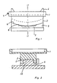
- Fig. 1 ein Ausführungsbeispiel der Vorrichtung in Seitenansicht,
- Fig. 2 die Vorrichtung nach Fig. 1 im Schnitt 11 - II der Fig. 1,
- Fig. 3 die Vorrichtung nach Fig. 1 in Kippstellung.
- Bei der Ausführungsform nach den Fig. 1 bis 3 ist an der Unterseite eines Aufnahmetellers 1 eine konvexbogenförmige Kufe 2 angeordnet, die eine Längsnut 3 aufweist. Auf den Aufnahmeteller 1 ist eine Modellhalterung 4 eingesetzt, die auf dem Aufnahmeteller 1 um 360° drehbar und mit Hilfe einer Stellschraube 9 auf dem Aufnahmeteller 1 fixierbar ist.
- Der Aufnahmeteller 1 ist mit seiner Kufe 2 auf ein als Sockel dienendes Komplementärteil 5 mit einer Rippe 10 aufgesetzt und entlang der Kufenbahn 6 derart verschiebbar, daß der Aufnahmeteller 1 von einer Stellung nach Fig. 1 in eine Stellung nach Fig. 3 gekippt wird. An der Seitenfläche der Kufe 2 und am Komplementärteil 5 sind einander zugeordnete Markierungen 7 bzw. 8 angebracht
- Ferner sind den Markierungen entsprechend Rasterungen vorgesehen, so daß der in Kippstellung stehende Aufnahmeteller 1 festgehalten bleibt und die gewünschte Markierstellung eindeutig wieder reproduzierbar ist. Durch einen nicht dargstellten Anschlag kann die Kippbewegung z. B. auf 6° begrenzt werden.
- Bei der Ausführungsform nach den Fig. 1 bis 3 wird ein Kippen des Aufnahmetellers 1 mit dem darauf fixierten Kiefermodell dadurch bewirkt, daß die Kufe 2 entlang der Kufenbahn 6 verschoben wird. Da die Kufenbahn nur eine geringe Krümmung aufweist, beschreibt die Kufe den Abschnitt eines verhältnismäßig großen Kreisbogen, dessen Achse außerhalb der Vorrichtung liegt.
- Mit Hilfe der erfindungsgemäßen Vorrichtung lassen sich das Kiefermodell sowohl zur Bestimmung der allgemeinen Bezugsachse als auch die einzelnen Zahnstümpfe zur Bestimmung der Abweichungen der Zahnlängsachsen von der allgemeinen Bezugsachse in die gewünschte Kippstellung bringen, und die ermittelten Lageveränderungen schnell und sehr genau wieder reproduzieren. Dabei ist es auch möglich, zwei Vorrichtungen aufeinander zu setzen, um mit Hilfe der einen Vorrichtung die allgemeine Bezugsachse zu bestimmen und mit Hilfe der anderen Vorrichtung die Achsen der Zahnstümpfe auf die allgemeine Bezugsachse auszurichten.
- Auch können Geräte mit unterschiedlichen Krümmungen für die Kippbewegung verwendet werden. So sind Geräte mit unterschiedlicher Kurvenbahn möglich.
Claims (4)
konvexbogenförmig und das Komplementärteil des Sockels (5) mit konkaver Oberfläche ausgebildet sind.
gekennzeichnet, daß die Kufe
konkavbogenförmig und das Komplementärteil des Sockels mit konvexer Oberfläche ausgebildet sind.
Priority Applications (4)
| Application Number | Priority Date | Filing Date | Title |
|---|---|---|---|
| EP85102383A EP0193627B1 (de) | 1985-03-04 | 1985-03-04 | Vorrichtung zum reproduzierbaren Ausrichten eines Kiefermodells |
| AT85102383T ATE36233T1 (de) | 1985-03-04 | 1985-03-04 | Vorrichtung zum reproduzierbaren ausrichten eines kiefermodells. |
| DE8585102383T DE3564184D1 (en) | 1985-03-04 | 1985-03-04 | Device for reproducible orientation of a jaw model |
| JP61045521A JPS61253052A (ja) | 1985-03-04 | 1986-03-04 | 顎型を繰り返し整列させるための装置 |
Applications Claiming Priority (1)
| Application Number | Priority Date | Filing Date | Title |
|---|---|---|---|
| EP85102383A EP0193627B1 (de) | 1985-03-04 | 1985-03-04 | Vorrichtung zum reproduzierbaren Ausrichten eines Kiefermodells |
Publications (2)
| Publication Number | Publication Date |
|---|---|
| EP0193627A1 EP0193627A1 (de) | 1986-09-10 |
| EP0193627B1 true EP0193627B1 (de) | 1988-08-10 |
Family
ID=8193341
Family Applications (1)
| Application Number | Title | Priority Date | Filing Date |
|---|---|---|---|
| EP85102383A Expired EP0193627B1 (de) | 1985-03-04 | 1985-03-04 | Vorrichtung zum reproduzierbaren Ausrichten eines Kiefermodells |
Country Status (4)
| Country | Link |
|---|---|
| EP (1) | EP0193627B1 (de) |
| JP (1) | JPS61253052A (de) |
| AT (1) | ATE36233T1 (de) |
| DE (1) | DE3564184D1 (de) |
Family Cites Families (4)
| Publication number | Priority date | Publication date | Assignee | Title |
|---|---|---|---|---|
| DE348185C (de) * | 1922-02-02 | Giuseppe Giovanni Battista Tar | Untergestell fuer Aufnahmekinematographen | |
| US2959857A (en) * | 1953-11-12 | 1960-11-15 | Stoll Victor | Dental analyzer and coordinator |
| US2796226A (en) * | 1954-03-29 | 1957-06-18 | Houston Fearless Corp | Camera cradle head |
| DE3306056C1 (de) * | 1983-02-22 | 1984-09-06 | Erich Dr. 5552 Morbach Faber | Vorrichtung zum Ausrichten der Zahnlängsachsen einzelner Zahnstümpfe eines Zahnmodelles |
-
1985
- 1985-03-04 EP EP85102383A patent/EP0193627B1/de not_active Expired
- 1985-03-04 DE DE8585102383T patent/DE3564184D1/de not_active Expired
- 1985-03-04 AT AT85102383T patent/ATE36233T1/de not_active IP Right Cessation
-
1986
- 1986-03-04 JP JP61045521A patent/JPS61253052A/ja active Pending
Also Published As
| Publication number | Publication date |
|---|---|
| JPS61253052A (ja) | 1986-11-10 |
| ATE36233T1 (de) | 1988-08-15 |
| EP0193627A1 (de) | 1986-09-10 |
| DE3564184D1 (en) | 1988-09-15 |
Similar Documents
| Publication | Publication Date | Title |
|---|---|---|
| EP0578969B1 (de) | Magnetanordnung für eine Prothese | |
| EP0176944B1 (de) | Verfahren und Vorrichtung zur Herstellung des auf einer Basisplatte festgelegten Modells eines Zahnkranzes | |
| DE2041929A1 (de) | Prothetisches Schultergelenk | |
| DE3010421A1 (de) | Instrument zum halten und einsetzen der tibiaplateaus fuer eine kniegelenk-gleitflaechenprothese | |
| EP0339530A2 (de) | Endoprothese für ein Gelenk | |
| DE10200690A1 (de) | Hilfsmittel zur Implantation einer Hüftgelenkendoprothese, sowie Verfahren für Handhabung derselben | |
| DE4211004C2 (de) | Zahnärztlicher Artikulator und zahnärztliches Artikulatorsystem | |
| DE2830566A1 (de) | Vorrichtung zum ausformen einer knochenoeffnung im hueftbein zum einsetzen einer kuenstlichen gelenkpfanne | |
| EP0513283B1 (de) | Vorrichtung zum schärfen, schleifen und polieren von dental-, parodontal- und/oder chirurgischen instrumenten | |
| DE2742674C2 (de) | Artikulator für die Kontrolle und Korrektur des Kauflächenprofils der Zähne | |
| EP0253757A1 (de) | Kiefermodell | |
| DE2825470A1 (de) | Registrierbesteck fuer die zahnprothetik | |
| DE3306056C1 (de) | Vorrichtung zum Ausrichten der Zahnlängsachsen einzelner Zahnstümpfe eines Zahnmodelles | |
| EP0193627B1 (de) | Vorrichtung zum reproduzierbaren Ausrichten eines Kiefermodells | |
| DE8623700U1 (de) | Chirurgisches Instrument zur Verdichtung von Spongiosa-Substanz | |
| DE102022133031B3 (de) | Zusammensetzbare Spielfigur | |
| DE3127446A1 (de) | Verfahren zum anbringen und halten eines duennen, flexiblen streifens innerhalb einer brillengestellfassung | |
| EP0391190B1 (de) | Artikulator für Kiefermodelle | |
| DE2922187C2 (de) | Sockel für Zahnmodelle | |
| DE2922087C2 (de) | Vorrichtung zum Befestigen von mit einem Sockel versehenen Gebißmodellen und Verfahren zum Montieren an der Vorrichtung | |
| DE3837551A1 (de) | Vorrichtung zum herstellen zahntechnischer kiefermodelle in form von saegeschnittmodellen nebst bausatz hierzu | |
| DE2922153A1 (de) | Artikulator fuer gnathologische zwecke | |
| EP1364630A2 (de) | Positionierhilfe für Gelenkprothese | |
| DE3913146C2 (de) | Vorrichtung zur Fixierung von Kiefergipsmodellen an einem Artikulator | |
| DE2703332A1 (de) | Ausrichtvorrichtung fuer ein bearbeitungswerkzeug |
Legal Events
| Date | Code | Title | Description |
|---|---|---|---|
| PUAI | Public reference made under article 153(3) epc to a published international application that has entered the european phase |
Free format text: ORIGINAL CODE: 0009012 |
|
| AK | Designated contracting states |
Kind code of ref document: A1 Designated state(s): AT BE CH DE FR GB IT LI LU NL SE |
|
| 17P | Request for examination filed |
Effective date: 19860910 |
|
| 17Q | First examination report despatched |
Effective date: 19870825 |
|
| RAP1 | Party data changed (applicant data changed or rights of an application transferred) |
Owner name: FABER, ERICH, DR. |
|
| GRAA | (expected) grant |
Free format text: ORIGINAL CODE: 0009210 |
|
| AK | Designated contracting states |
Kind code of ref document: B1 Designated state(s): AT BE CH DE FR GB IT LI LU NL SE |
|
| PG25 | Lapsed in a contracting state [announced via postgrant information from national office to epo] |
Ref country code: BE Effective date: 19880810 Ref country code: NL Effective date: 19880810 |
|
| REF | Corresponds to: |
Ref document number: 36233 Country of ref document: AT Date of ref document: 19880815 Kind code of ref document: T |
|
| REF | Corresponds to: |
Ref document number: 3564184 Country of ref document: DE Date of ref document: 19880915 |
|
| ITF | It: translation for a ep patent filed | ||
| GBT | Gb: translation of ep patent filed (gb section 77(6)(a)/1977) | ||
| ET | Fr: translation filed | ||
| NLV1 | Nl: lapsed or annulled due to failure to fulfill the requirements of art. 29p and 29m of the patents act | ||
| PG25 | Lapsed in a contracting state [announced via postgrant information from national office to epo] |
Ref country code: GB Effective date: 19890304 Ref country code: AT Effective date: 19890304 |
|
| PG25 | Lapsed in a contracting state [announced via postgrant information from national office to epo] |
Ref country code: SE Effective date: 19890305 |
|
| ITTA | It: last paid annual fee | ||
| PG25 | Lapsed in a contracting state [announced via postgrant information from national office to epo] |
Ref country code: LU Free format text: LAPSE BECAUSE OF NON-PAYMENT OF DUE FEES Effective date: 19890331 |
|
| PLBE | No opposition filed within time limit |
Free format text: ORIGINAL CODE: 0009261 |
|
| STAA | Information on the status of an ep patent application or granted ep patent |
Free format text: STATUS: NO OPPOSITION FILED WITHIN TIME LIMIT |
|
| PGFP | Annual fee paid to national office [announced via postgrant information from national office to epo] |
Ref country code: FR Payment date: 19890714 Year of fee payment: 5 |
|
| PGFP | Annual fee paid to national office [announced via postgrant information from national office to epo] |
Ref country code: CH Payment date: 19890720 Year of fee payment: 5 |
|
| 26N | No opposition filed | ||
| GBPC | Gb: european patent ceased through non-payment of renewal fee | ||
| PG25 | Lapsed in a contracting state [announced via postgrant information from national office to epo] |
Ref country code: LI Effective date: 19900331 Ref country code: CH Effective date: 19900331 |
|
| REG | Reference to a national code |
Ref country code: CH Ref legal event code: PL |
|
| PGFP | Annual fee paid to national office [announced via postgrant information from national office to epo] |
Ref country code: DE Payment date: 19910514 Year of fee payment: 7 |
|
| PG25 | Lapsed in a contracting state [announced via postgrant information from national office to epo] |
Ref country code: DE Effective date: 19921201 |
|
| EUG | Se: european patent has lapsed |
Ref document number: 85102383.8 Effective date: 19891016 |
|
| PG25 | Lapsed in a contracting state [announced via postgrant information from national office to epo] |
Ref country code: FR Effective date: 19950731 |
|
| REG | Reference to a national code |
Ref country code: FR Ref legal event code: ST |
|
| PG25 | Lapsed in a contracting state [announced via postgrant information from national office to epo] |
Ref country code: FR Effective date: 19900331 |