EP0193702B1 - Robinet mélangeur, en particulier à levier unique - Google Patents
Robinet mélangeur, en particulier à levier unique Download PDFInfo
- Publication number
- EP0193702B1 EP0193702B1 EP19860100222 EP86100222A EP0193702B1 EP 0193702 B1 EP0193702 B1 EP 0193702B1 EP 19860100222 EP19860100222 EP 19860100222 EP 86100222 A EP86100222 A EP 86100222A EP 0193702 B1 EP0193702 B1 EP 0193702B1
- Authority
- EP
- European Patent Office
- Prior art keywords
- water
- fitting according
- mixing fitting
- water mixing
- measuring circuit
- Prior art date
- Legal status (The legal status is an assumption and is not a legal conclusion. Google has not performed a legal analysis and makes no representation as to the accuracy of the status listed.)
- Expired
Links
- XLYOFNOQVPJJNP-UHFFFAOYSA-N water Substances O XLYOFNOQVPJJNP-UHFFFAOYSA-N 0.000 claims description 160
- 238000007789 sealing Methods 0.000 claims description 14
- 239000004973 liquid crystal related substance Substances 0.000 claims description 3
- 230000015572 biosynthetic process Effects 0.000 claims 1
- 238000009529 body temperature measurement Methods 0.000 description 10
- 238000010586 diagram Methods 0.000 description 3
- 230000005611 electricity Effects 0.000 description 3
- 238000005516 engineering process Methods 0.000 description 3
- 239000000919 ceramic Substances 0.000 description 2
- 238000010276 construction Methods 0.000 description 2
- 238000000034 method Methods 0.000 description 2
- 230000003287 optical effect Effects 0.000 description 2
- 206010053615 Thermal burn Diseases 0.000 description 1
- 239000005457 ice water Substances 0.000 description 1
- 239000000203 mixture Substances 0.000 description 1
- 230000004048 modification Effects 0.000 description 1
- 238000012986 modification Methods 0.000 description 1
- 229920003023 plastic Polymers 0.000 description 1
- 125000006850 spacer group Chemical group 0.000 description 1
- 230000007704 transition Effects 0.000 description 1
Images


Classifications
-
- F—MECHANICAL ENGINEERING; LIGHTING; HEATING; WEAPONS; BLASTING
- F16—ENGINEERING ELEMENTS AND UNITS; GENERAL MEASURES FOR PRODUCING AND MAINTAINING EFFECTIVE FUNCTIONING OF MACHINES OR INSTALLATIONS; THERMAL INSULATION IN GENERAL
- F16K—VALVES; TAPS; COCKS; ACTUATING-FLOATS; DEVICES FOR VENTING OR AERATING
- F16K37/00—Special means in or on valves or other cut-off apparatus for indicating or recording operation thereof, or for enabling an alarm to be given
-
- F—MECHANICAL ENGINEERING; LIGHTING; HEATING; WEAPONS; BLASTING
- F16—ENGINEERING ELEMENTS AND UNITS; GENERAL MEASURES FOR PRODUCING AND MAINTAINING EFFECTIVE FUNCTIONING OF MACHINES OR INSTALLATIONS; THERMAL INSULATION IN GENERAL
- F16K—VALVES; TAPS; COCKS; ACTUATING-FLOATS; DEVICES FOR VENTING OR AERATING
- F16K37/00—Special means in or on valves or other cut-off apparatus for indicating or recording operation thereof, or for enabling an alarm to be given
- F16K37/0025—Electrical or magnetic means
- F16K37/005—Electrical or magnetic means for measuring fluid parameters
-
- F—MECHANICAL ENGINEERING; LIGHTING; HEATING; WEAPONS; BLASTING
- F16—ENGINEERING ELEMENTS AND UNITS; GENERAL MEASURES FOR PRODUCING AND MAINTAINING EFFECTIVE FUNCTIONING OF MACHINES OR INSTALLATIONS; THERMAL INSULATION IN GENERAL
- F16K—VALVES; TAPS; COCKS; ACTUATING-FLOATS; DEVICES FOR VENTING OR AERATING
- F16K11/00—Multiple-way valves, e.g. mixing valves; Pipe fittings incorporating such valves
- F16K11/02—Multiple-way valves, e.g. mixing valves; Pipe fittings incorporating such valves with all movable sealing faces moving as one unit
- F16K11/06—Multiple-way valves, e.g. mixing valves; Pipe fittings incorporating such valves with all movable sealing faces moving as one unit comprising only sliding valves, i.e. sliding closure elements
- F16K11/078—Multiple-way valves, e.g. mixing valves; Pipe fittings incorporating such valves with all movable sealing faces moving as one unit comprising only sliding valves, i.e. sliding closure elements with pivoted and linearly movable closure members
- F16K11/0782—Single-lever operated mixing valves with closure members having flat sealing faces
- F16K11/0787—Single-lever operated mixing valves with closure members having flat sealing faces with both the supply and the discharge passages being on the same side of the closure members
-
- G—PHYSICS
- G05—CONTROLLING; REGULATING
- G05D—SYSTEMS FOR CONTROLLING OR REGULATING NON-ELECTRIC VARIABLES
- G05D23/00—Control of temperature
- G05D23/01—Control of temperature without auxiliary power
- G05D23/13—Control of temperature without auxiliary power by varying the mixing ratio of two fluids having different temperatures
- G05D23/1393—Control of temperature without auxiliary power by varying the mixing ratio of two fluids having different temperatures characterised by the use of electric means
-
- E—FIXED CONSTRUCTIONS
- E03—WATER SUPPLY; SEWERAGE
- E03C—DOMESTIC PLUMBING INSTALLATIONS FOR FRESH WATER OR WASTE WATER; SINKS
- E03C1/00—Domestic plumbing installations for fresh water or waste water; Sinks
- E03C1/02—Plumbing installations for fresh water
- E03C1/04—Water-basin installations specially adapted to wash-basins or baths
- E03C2001/0418—Water-basin installations specially adapted to wash-basins or baths having temperature indicating means
-
- Y—GENERAL TAGGING OF NEW TECHNOLOGICAL DEVELOPMENTS; GENERAL TAGGING OF CROSS-SECTIONAL TECHNOLOGIES SPANNING OVER SEVERAL SECTIONS OF THE IPC; TECHNICAL SUBJECTS COVERED BY FORMER USPC CROSS-REFERENCE ART COLLECTIONS [XRACs] AND DIGESTS
- Y10—TECHNICAL SUBJECTS COVERED BY FORMER USPC
- Y10S—TECHNICAL SUBJECTS COVERED BY FORMER USPC CROSS-REFERENCE ART COLLECTIONS [XRACs] AND DIGESTS
- Y10S323/00—Electricity: power supply or regulation systems
- Y10S323/906—Solar cell systems
-
- Y—GENERAL TAGGING OF NEW TECHNOLOGICAL DEVELOPMENTS; GENERAL TAGGING OF CROSS-SECTIONAL TECHNOLOGIES SPANNING OVER SEVERAL SECTIONS OF THE IPC; TECHNICAL SUBJECTS COVERED BY FORMER USPC CROSS-REFERENCE ART COLLECTIONS [XRACs] AND DIGESTS
- Y10—TECHNICAL SUBJECTS COVERED BY FORMER USPC
- Y10T—TECHNICAL SUBJECTS COVERED BY FORMER US CLASSIFICATION
- Y10T137/00—Fluid handling
- Y10T137/8158—With indicator, register, recorder, alarm or inspection means
-
- Y—GENERAL TAGGING OF NEW TECHNOLOGICAL DEVELOPMENTS; GENERAL TAGGING OF CROSS-SECTIONAL TECHNOLOGIES SPANNING OVER SEVERAL SECTIONS OF THE IPC; TECHNICAL SUBJECTS COVERED BY FORMER USPC CROSS-REFERENCE ART COLLECTIONS [XRACs] AND DIGESTS
- Y10—TECHNICAL SUBJECTS COVERED BY FORMER USPC
- Y10T—TECHNICAL SUBJECTS COVERED BY FORMER US CLASSIFICATION
- Y10T137/00—Fluid handling
- Y10T137/8593—Systems
- Y10T137/86493—Multi-way valve unit
- Y10T137/86815—Multiple inlet with single outlet
Definitions
- the invention relates to a water mixer fitting, in particular a single-lever mixer fitting, with on the one hand preferably two water inlets, two water inlet valves, a mixing chamber, an ice water outlet, possibly a water outlet valve and at least one actuator for the water inlet valves and possibly the water outlet valve and with an electronic temperature measuring circuit, on the one hand, the Temperature measuring circuit arranged in the mixed water outlet temperature sensor, a mixed temperature display and a current source, for. B. has a battery or an accumulator.
- Water mixer taps of the type in question are known for wash basins, bathtubs, showers, bidets, etc. They are generally used to mix water of different temperatures - cold water and hot water - flowing in via the water inlets to mixed water of a desired temperature flowing out at the mixed water outlet. So that you can determine how high the temperature of the mixed water is, for example not to scald yourself with water that is too hot, the water mixer taps of the type from which the invention is based have a temperature measuring circuit, which then also includes a mixed temperature display.
- each water inlet valve was previously assigned its own actuating element in the form of a control handle, but that single lever mixer taps are increasingly being used today.
- the water inlet valves are usually adjusted to achieve the desired mixture and the desired quantity by rotating and tilting a single actuating element in the form of a rotary and rocking lever.
- the actuator can also be designed as a rotary and slide lever instead of as a rotary and rocker arm.
- the known water mixer tap from which the invention is based, is known both as a classic water mixer tap with two actuating members and as a modern single-lever mixer tap with only one actuating member (cf. DE-A-3 045 531, on the one hand FIGS. 1 to 4, on the other hand, FIGS. 7 and 8).
- the temperature sensor which is designed here as a resistance sensor, projects into the free end of the mixed water outlet.
- the temperature sensor is connected with connecting lines to the rest of the temperature measuring circuit, which is arranged at the rear of the water mixer fitting.
- the temperature measuring circuit has a bridge circuit with which the setpoint of the temperature of the mixed water can be set.
- optical display elements preferably colored lamps, which provide information about the temperature of the mixed water. Depending on whether the setpoint temperature of the mixed water has been exceeded or fallen below, the optical display element lights up, the associated water inlet valve of which requires a change in the setting.
- the temperature measuring circuit has a battery or an accumulator as the current source.
- the battery here and below always stands for a primary element that cannot be recharged, while the battery here and below always stands for a secondary element that can be recharged).
- the mixed temperature display is only switched on when the water mixer tap is in operation. This switching on takes place by means of a flow sensor which detects the flow at the mixed water outlet (cf. FIG. 1 of DE-A-3 045 531).
- the temperature measurement circuit with the mixed temperature display is only activated if there is sufficient flow.
- the water mixer fitting explained at the beginning, from which the invention is based, requires frequent replacement of the battery or frequent recharging of the rechargeable battery despite the envisaged power saving measures.
- the overall design requires relatively extensive changes to the water mixing valve, including in the area of the mixed water outlet, and the information obtained with the mixing temperature display of this water mixing valve is not particularly suitable for normal applications. Overall, the known water mixer fitting explained at the outset is therefore unsuitable for widespread use in practice.
- the invention is based on the object of specifying a water mixer fitting with an electronic temperature measurement circuit which meets the practical requirements corresponds optimally in terms of electronic circuit technology, mechanical design and application technology, especially, but not only, taking into account the special circumstances of single-lever mixer taps.
- the water mixer fitting according to the invention in which the above-mentioned object is achieved, is first and essentially characterized in that the temperature measuring circuit has, in addition to the first current source embodied as a battery or accumulator, a solar cell or several solar cells as a further current source and above a predetermined upper brightness limit value only the solar cell is effective as a current source for the temperature control circuit.
- the temperature measuring circuit has, in addition to the first current source embodied as a battery or accumulator, a solar cell or several solar cells as a further current source and above a predetermined upper brightness limit value only the solar cell is effective as a current source for the temperature control circuit.
- the temperature measuring circuit has, in addition to the first current source embodied as a battery or accumulator, a solar cell or several solar cells as a further current source and above a predetermined upper brightness limit value only the solar cell is effective as a current source for the temperature control circuit.
- the battery or the accumulator acts as a current source for the temperature measurement circuit below
- the main idea of the invention is therefore to provide a solar cell or several solar cells as a current source for the temperature measuring circuit in addition to the battery or the accumulator and to ensure that above a predetermined upper brightness limit value, if it is sufficiently bright, only the solar cell or the solar cells are effective as a current source for the temperature measuring circuit. If it is additionally realized that only the battery or the accumulator is effective as a current source for the temperature measuring circuit below a predetermined average brightness limit value and that neither the solar cell nor the battery or the accumulator are effective as a current source for the temperature measuring circuit below a predetermined lower brightness limit value overall minimal power consumption achieved. Above a predetermined upper brightness limit value, that is if it is sufficiently bright, the temperature measuring circuit works without loading the battery or the accumulator.
- the teaching of the invention is generally concerned with water mixer taps and is only explained for the sake of simplicity on the basis of exemplary embodiments of single lever mixer taps. However, a large number of aspects of the teaching of the invention can also be implemented in a corresponding manner in water mixer taps with two actuating members.
- the teaching of the invention can also be applied to water fittings to which mixed water or heated water is already supplied.
- the teaching of the invention can also be used for temperature measurement circuits used for other purposes, e.g. B. for room temperature displays, also in connection with watches, for body thermometers, for thermo bottles, for baby bottles, etc., are used.
- the type of power supply of a temperature measuring circuit according to the invention can finally be easily transferred to other measuring circuits, z. B. on measuring circuits for barometers and hygrometers.
- the water mixer fitting 1 shown in FIG. 1 in a first preferred embodiment as a single lever mixer fitting can be explained quite well in its basic structure in connection with FIG. 2.
- the water mixing valve 1 initially has two water inlets 2 and two water inlet valves 3 assigned to the water inlets 2. 1 and 2, only one water inlet 2 and one water inlet valve 3 can be seen in each case.
- One of the water inlets 2 is connected to a hot water inlet, the other water inlet 2 is connected to a cold water inlet.
- the water inlet valves 3 are formed by the openings which can be brought into different overlaps in ceramic disks which can be moved onto one another. This technique has long been known as such and requires no further explanation here.
- a mixing chamber 4 is provided, which is on the one hand in connection with the water inlets 2, on the other hand, with a mixed water outlet 5, namely via a water outlet valve 6, in connection.
- the previously explained parts of the water mixer fitting 1 are combined in a cartridge 7 designed as a closed block.
- Fig. 1 shows that from the cartridge 7 protrudes only one actuating lever 8, with the aid of which a ceramic disc 9 shown in Fig. 2 above for opening and closing the water inlet valves 3 and the water outlet valve 6 is movable.
- a spacer and swivel ring 10 is placed on the cartridge 7, on which in turn an actuator 11 is then placed.
- the actuator 11 By means of the actuator 11, the water inlet valves 3 and the water outlet valve 6 are actuated via the actuating lever 8. Because of the design of the water mixing valve 1 as a lifting mixing valve, the actuator is a rotary and rocker arm. 2 shows a housing 12, which is not shown in FIG. 1.
- 3 shows the block diagram of an electronic temperature measuring circuit 13 with a temperature sensor 14 arranged in the mixed water outlet 5;
- the temperature sensor 14 can be seen schematically in FIG. 2, but in the block diagram according to FIG. 3 it is part of a temperature measuring block 15.
- Part of the temperature measuring block 15 in FIG. 3 is also a mixed temperature display 16.
- the temperature measuring circuit 13 initially has a battery 17 as the current source. 3 then shows that, according to the teaching of the invention, the temperature measuring circuit 13 has, in addition to the first current source designed as a battery 17, a solar cell 18 as a further current source. Circuitry measures, which are explained below, ensure that above a predetermined upper brightness limit value only the solar cell 18 is effective as a current source for the temperature measuring circuit 13, that below a predetermined average brightness limit value only the battery 17 is effective as a current source for the temperature measuring circuit 13 and that below a predetermined lower brightness limit, neither the solar cell 18 nor the battery 17 are effective as a current source for the temperature measuring circuit 13.
- the temperature measuring circuit 13 also includes an auxiliary switch 19 and two switching diodes 20, 21.
- the solar cell 18 is effective as a current source for the temperature measuring circuit 13, although the auxiliary switch 19 is closed. This is achieved in that the voltage of the solar cell 18 is greater than the voltage of the battery 17, so that although current can flow from the solar cell 18 via the switching diode 20 and the temperature measuring block 15, the switching diode 21 prevents current from the battery 17 can flow. The switching diode 21 naturally also prevents current from flowing from the solar cell 18 via the battery 17.
- the solar cell 18 and the battery 17 act as current sources for the temperature measuring circuit 13. This results from the current-voltage characteristics of solar cells.
- the battery 18 is effective as a current source for the temperature measuring circuit 13. This results from the fact that the voltage of the battery 17 is now greater than the voltage of the solar cell 18, so that the switching diode 20 prevents a current from flowing from the solar cell 18. The switching diode 20 prevents of course also that current flows from the battery 17 via the solar cell 18.
- the water mixer fitting 1 is exposed to a brightness which is below a predetermined lower brightness limit value, for example the illuminance is less than 5 lux, then neither the solar cell 18 nor the battery 17 are effective as a current source for the temperature measuring circuit 13. On the one hand, the voltage of the solar cell 18 is then insufficient, on the other hand, the auxiliary switch 19 is then opened, controlled by the solar cell 18, so that no current can flow from the battery 18.
- a predetermined lower brightness limit value for example the illuminance is less than 5 lux
- a battery 17 is provided as the first current source.
- the first current source could also be designed as an accumulator.
- a modification of the temperature measuring circuit 13 could then be expedient in such a way that the accumulator can be charged by the solar cell 18.
- the lamps known in the prior art can be used as the mixing temperature display 16.
- the mixed temperature display 16 corresponds to modern technology to design the mixed temperature display 16 as a liquid crystal number display or as a LED display.
- a liquid crystal numerical display has a lower power consumption, but requires additional lighting so that it can be read in the dark.
- a LED number display constantly has a slightly higher power consumption, but can also be read in the dark. It depends on the respective application, which of the two options you choose.
- a water mixer fitting according to the invention for bathtubs or the like can be designed in such a way that a target value is sensed at the temperature measuring circuit to sense the water level in the bathtub or the like.
- the water level-specifying water level sensor is connected and an acoustic warning signal, a switching signal or the like can be emitted by the temperature measuring circuit when the desired water level is reached.
- the temperature sensor 14 can be used in a ring surrounding the mixed water outlet 5, preferably arranged next to the mixing chamber 4.
- this ring is part of a sensor plate 24 having passages 22, 23 assigned to the water inlets 2 and the mixed water outlet 5.
- the sensor plate 24 acts as an intermediate layer between the cartridge 7 and the housing 12, so that little needs to be changed as such on the water mixer fitting 1.
- the dimensions of the sensor plate 24 must of course be matched to the dimensions of the corresponding water mixer fitting 1.
- a thickness of the sensor plate 24 of 4 to 7 mm, preferably a thickness of approximately 5.5 mm, and a diameter of approximately 48 mm have proven to be particularly suitable for the conventional single-lever mixer taps.
- both the inflowing water and the outflowing mixed water flow through the sensor plate 24, which therefore requires sealing against the cartridge 7 on the one hand and the housing 12 on the other hand.
- the seal against the cartridge 7 serve Usually on the underside of the cartridge 7, the water inlets 2 and the mixed water outlet 5 surrounding sealing rings.
- the sensor plate 24 is provided on the underside with receiving grooves 25 for the sealing rings 26 surrounding the passages 22, 23 according to the preferred teaching of the invention. Corresponding receiving grooves can of course also be provided on the upper side of the sensor plate 24 if this is expedient for design reasons. 5 to 7 show this particularly clearly.
- the sensor plate 24 has a receiving bore 27 for the temperature sensor 14 which extends radially to the passage 23 assigned to the mixed water outlet 5 and extends from the edge of the sensor plate 24 to the passage 23 and the temperature sensor 14 can be inserted sealingly into the receiving bore 27.
- the preferred embodiment shown in the drawing makes it clear that it is particularly useful if the temperature sensor 14 is provided with an external thread 28 and the receiving bore 27 with a corresponding internal thread 29 and that preferably between a circumferential sealing surface 30 on the temperature sensor 14 and a circumferential Sealing surface 31 in the receiving bore 27, a sealing element 32 is arranged.
- Fig. 7 shows clearly that the temperature sensor 14 is provided on the side facing the outer edge of the sensor plate 24 with a screwdriver slot 34 so that it can be screwed into the receiving bore 27 without further notice.
- Other forms of actuation are of course also conceivable here.
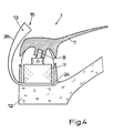
- Fig. 4 shows a special embodiment of the water mixer fitting 1 according to the invention, in which the sensor plate 24 carries an extension 35 which receives the temperature measuring circuit 13.
- the attachment part 35 is guided upward in an arc on the side facing away from the actuating end of the actuating member 11 and carries the mixed temperature display 16 at the upper end in a manner which is very clearly visible to an actuating person.
- the attachment part carries a jack for plugging in the mixing temperature.
- the mixed temperature display is separated from the attachment part, but can be plugged into the attachment part.
- FIG. 4 The embodiment of a water mixer fitting 1 according to the invention shown in FIG. 4 requires an adapted overall construction of the housing 12, in particular because of the extension 35 which is led out to the rear. It is of course particularly expedient if the overall construction of a water mixer fitting 1 can be maintained essentially without a temperature indicator. How this is possible is explained in detail below.
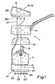
- Fig. 1 shows the water mixing temperature 1 in the embodiment as a single-lever mixer fitting, in which the actuator 11 carries a cover cap on the top in a manner known per se.
- this cover cap is designed as a desk-like attachment part 36 which receives the mixed temperature display 16 and is connected or connectable via lines 37 to the temperature sensor 14 or to the sensor plate 24. With the aid of snap-in connections 38, the attachment part 36 can be snapped onto the actuating member 11 practically in the same way as the cover cap otherwise used.
- other connection techniques are also possible here.
- the attachment part 36 has connector body 39 for detachable connection of the electrical lines 37.
- the connector body 39 are formed in the embodiment shown here as sockets; accordingly, the associated ends of the lines 37 are provided with plugs.
- Other configurations, for example as spring-loaded terminals or the like, are of course also conceivable for the connector body 39.
- the connector body 39 are, according to the preferred teaching of the invention, executed separately per line 37 and protected in a special way against moisture and splash water, so that between the connector bodies 39, d. H. the lines 37, can not form short-circuit bridges.
- the temperature measuring circuit 13 is arranged in the top part 36.
- the solar cell 18 is also arranged on the top of the top part 36. In the exemplary embodiment shown here, this is a solar cell group.
- the battery 17 is also indicated in a conventional clamped version.
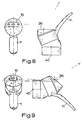
- Fig. 8 shows the water mixer fitting 1 in the arrangement and configuration for a sink.
- the direction of view of an actuating person is indicated here by a dashed line. It is essential that the top of the top part 36 through the wedge-shaped design of the attachment part 36 in the direction of the operator is suitable. In the application shown in FIG. 8, the forward inclination toward the actuating end of the actuating member 11 is selected.
- the realization of the inclination by the wedge-shaped design of the attachment part 36 has the advantage that this inclination can be changed by moving the attachment part 36.
- FIG. 9 shows the object from FIG. 8 with an implemented attachment part 36 in the arrangement on the wall of a shower cubicle. The operator's line of sight is indicated accordingly.
- the angle of inclination of the top of the attachment part 36 according to the preferred teaching of the invention when the actuator 11 is in the closed position is approximately 80 to 50 °, preferably approximately 70 °, based on the main axis 40 of the water mixer fitting 1 is.
- the attachment part 36 has an annular, upwardly open socket 41, which can preferably be snapped onto the actuating member 11, and an electronic module 42 which can be inserted sealingly into the socket 41.
- This electronics module 42 is sealed from the socket 41 by a circumferential sealing ring 43 and covered by a transparent plastic cap 44.
- Connection lines 45 lead from the electronics module 42 to the connection bodies 39.
Landscapes
- Engineering & Computer Science (AREA)
- General Engineering & Computer Science (AREA)
- Mechanical Engineering (AREA)
- Physics & Mathematics (AREA)
- General Physics & Mathematics (AREA)
- Automation & Control Theory (AREA)
- Domestic Plumbing Installations (AREA)
- Indication Of The Valve Opening Or Closing Status (AREA)
- Multiple-Way Valves (AREA)
- Control Of Temperature (AREA)
- Mixers Of The Rotary Stirring Type (AREA)
Claims (27)
Priority Applications (1)
| Application Number | Priority Date | Filing Date | Title |
|---|---|---|---|
| AT86100222T ATE38889T1 (de) | 1985-03-04 | 1986-01-09 | Wassermischarmatur, insbesondere einhebelmischarmatur. |
Applications Claiming Priority (6)
| Application Number | Priority Date | Filing Date | Title |
|---|---|---|---|
| DE3507559 | 1985-03-04 | ||
| DE3507559 | 1985-03-04 | ||
| DE19853508680 DE3508680A1 (de) | 1985-03-04 | 1985-03-12 | Wassermischarmatur, insbesondere einhebelmischarmatur |
| DE3508680 | 1985-03-12 | ||
| DE3513549 | 1985-04-16 | ||
| DE19853513549 DE3513549A1 (de) | 1985-03-04 | 1985-04-16 | Wassermischarmatur, insbesondere einhebelmischarmatur |
Publications (3)
| Publication Number | Publication Date |
|---|---|
| EP0193702A2 EP0193702A2 (fr) | 1986-09-10 |
| EP0193702A3 EP0193702A3 (en) | 1987-04-15 |
| EP0193702B1 true EP0193702B1 (fr) | 1988-11-23 |
Family
ID=27192859
Family Applications (1)
| Application Number | Title | Priority Date | Filing Date |
|---|---|---|---|
| EP19860100222 Expired EP0193702B1 (fr) | 1985-03-04 | 1986-01-09 | Robinet mélangeur, en particulier à levier unique |
Country Status (11)
| Country | Link |
|---|---|
| US (1) | US4682626A (fr) |
| EP (1) | EP0193702B1 (fr) |
| JP (1) | JPH0631652B2 (fr) |
| KR (1) | KR920008607B1 (fr) |
| AU (1) | AU588285B2 (fr) |
| BR (1) | BR8600911A (fr) |
| CA (1) | CA1260730A (fr) |
| CH (1) | CH672356A5 (fr) |
| DE (1) | DE3661292D1 (fr) |
| GR (1) | GR860297B (fr) |
| MX (1) | MX162393A (fr) |
Cited By (1)
| Publication number | Priority date | Publication date | Assignee | Title |
|---|---|---|---|---|
| WO2016016652A3 (fr) * | 2014-08-01 | 2016-07-14 | Chargepoint Technology Limited | Système et procédé de surveillance configurables |
Families Citing this family (32)
| Publication number | Priority date | Publication date | Assignee | Title |
|---|---|---|---|---|
| ATE77457T1 (de) * | 1987-09-22 | 1992-07-15 | Kwc Ag | Elektrisch gesteuerte armatur. |
| EP0386212A4 (en) * | 1988-09-14 | 1992-03-11 | Chang Hwan Lee | Automatic mixing faucet |
| US4968152A (en) * | 1988-11-17 | 1990-11-06 | American Standard Inc. | Electric immersion thermometer |
| US4941608A (en) * | 1988-12-23 | 1990-07-17 | Matsushita Electric Works, Ltd. | Hot water supplying system |
| DE3903997A1 (de) * | 1989-02-10 | 1990-08-16 | Grohe Armaturen Friedrich | Mischventil fuer sanitaerarmaturen |
| US4979539A (en) * | 1989-02-23 | 1990-12-25 | Rohr Hans Josef | Sanitary mixing valve |
| US5462224A (en) * | 1990-10-05 | 1995-10-31 | Toto Ltd. | Hot and cold water mixing discharge device |
| JP2874322B2 (ja) * | 1990-10-05 | 1999-03-24 | 東陶機器株式会社 | 湯水混合水栓 |
| CN2150416Y (zh) * | 1993-01-11 | 1993-12-22 | 黄建达 | 带有液晶温度显示器的水龙头 |
| US5542449A (en) * | 1994-07-13 | 1996-08-06 | Huang; Chien-Ta | Single-outlet hot/cold water faucet with a water temperature display device |
| DE19602377C2 (de) * | 1996-01-24 | 2001-04-05 | Sanitaer Elektrohandel Heike M | Rohrverbinder |
| US5915415A (en) * | 1997-07-17 | 1999-06-29 | Huang; Tien-Tsai | Flow control valve assembly with temperature indicating capability for a water conveying device |
| EP1377768B1 (fr) * | 2001-04-10 | 2006-12-13 | Smart Flow Pty Ltd | Surveillance d'une vanne de regulation |
| US7252431B1 (en) * | 2003-10-28 | 2007-08-07 | Caramanna A Gregory | Water temperature monitoring apparatus |
| US7475827B2 (en) | 2005-04-19 | 2009-01-13 | Masco Corporation Of Indiana | Fluid mixer |
| US7458520B2 (en) | 2005-04-19 | 2008-12-02 | Masco Corporation Of Indiana | Electronic proportioning valve |
| US7448553B2 (en) | 2005-04-19 | 2008-11-11 | Masco Corporation Of Indiana | Fluid mixer |
| US7584898B2 (en) | 2005-07-01 | 2009-09-08 | Masco Corporation Of Indiana | Manual override for electronic proportioning valve |
| ES2302611B1 (es) * | 2006-04-03 | 2009-05-20 | Griferias Grober, S.L. | Sistema de recarga de bateria para griferia. |
| CN100445612C (zh) * | 2006-12-30 | 2008-12-24 | 崔忠民 | 带温度显示装置的水龙头 |
| US20080283786A1 (en) * | 2007-05-18 | 2008-11-20 | Snodgrass David L | Infrared retrofit faucet controller |
| US8327882B2 (en) * | 2007-11-15 | 2012-12-11 | Xiamen Lota International Co., Ltd. | Water faucet with joystick cartridge |
| GB2455728A (en) * | 2007-12-18 | 2009-06-24 | Weston Aerospace Ltd | Air temperature sensing on aircraft |
| US20100006166A1 (en) * | 2008-07-10 | 2010-01-14 | Jui-Chien Chen | Drinking faucet with monitoring device |
| US8316883B1 (en) * | 2009-03-09 | 2012-11-27 | Craig Watson | Water faucet temperature gauge and display |
| EP2823107A4 (fr) | 2012-03-07 | 2016-06-15 | Moen Inc | Raccord d'équipement de plomberie électronique |
| US20130248011A1 (en) * | 2012-03-21 | 2013-09-26 | Guo Yuan Hardware Co., Ltd. | Faucet control valve |
| CN103775676A (zh) * | 2012-10-17 | 2014-05-07 | 肖伟峰 | 一种冷热水龙头 |
| DE202013002188U1 (de) | 2013-03-08 | 2014-06-11 | Neoperl Gmbh | Sanitäres Einbauteil, Innenschlauchanordnung für eine Sanitärarmatur und Sanitärarmatur |
| US10184575B2 (en) * | 2017-01-11 | 2019-01-22 | Kohler Co. | Faucet with multi-directional controls |
| PL3690292T3 (pl) * | 2017-09-29 | 2021-11-02 | I Components Studio, S.L | Jednodźwigniowy inteligentny wkład do mocowania kranu oraz jednodźwigniowe inteligentne mocowanie kranu |
| DE102021131208A1 (de) * | 2021-11-29 | 2023-06-01 | Grohe Ag | Sanitärarmatur mit einer Mischkartusche |
Citations (1)
| Publication number | Priority date | Publication date | Assignee | Title |
|---|---|---|---|---|
| DE3045531A1 (de) * | 1980-12-03 | 1982-07-01 | Jean Kathleen 99511 Anchorage Alas. Perkins | "geraet zur anzeige der mischtemperatur von fluiden" |
Family Cites Families (11)
| Publication number | Priority date | Publication date | Assignee | Title |
|---|---|---|---|---|
| US3178150A (en) * | 1963-07-22 | 1965-04-13 | Stanley L Johnson | Bottom outlet valve for a mixing vessel |
| US3960016A (en) * | 1974-02-14 | 1976-06-01 | Symmons Industries, Inc. | Water mixing valve with temperature indicator |
| US4122396A (en) * | 1974-08-01 | 1978-10-24 | Grazier James A | Stable solar power source for portable electrical devices |
| US4017725A (en) * | 1975-01-03 | 1977-04-12 | Litton Business Systems, Inc. | Solar powered portable calculator |
| US4661758A (en) * | 1980-02-22 | 1987-04-28 | Lane S. Garrett | Solar power supply and battery charging circuit |
| JPS57182670U (fr) * | 1981-05-15 | 1982-11-19 | ||
| US4406398A (en) * | 1981-12-21 | 1983-09-27 | Perkins Jean K | Fluid temperature blending control |
| US4509550A (en) * | 1982-08-24 | 1985-04-09 | Monk Kermit R | Water temperature display and flow control apparatus |
| JPS59217074A (ja) * | 1983-05-07 | 1984-12-07 | Inax Corp | 自動給水装置 |
| DE3330585A1 (de) * | 1983-08-25 | 1985-03-07 | Walter Dipl.-Ing. 6908 Wiesloch Brunnenkant | Zapfstelle fuer fluessigkeiten |
| US4575262A (en) * | 1983-11-22 | 1986-03-11 | Anderstat Controls | Temperature indicator for a fluid fixture |
-
1986
- 1986-01-09 EP EP19860100222 patent/EP0193702B1/fr not_active Expired
- 1986-01-09 DE DE8686100222T patent/DE3661292D1/de not_active Expired
- 1986-01-30 CH CH386/86A patent/CH672356A5/de not_active IP Right Cessation
- 1986-01-31 GR GR860297A patent/GR860297B/el unknown
- 1986-03-03 KR KR1019860001465A patent/KR920008607B1/ko not_active Expired
- 1986-03-03 AU AU54333/86A patent/AU588285B2/en not_active Ceased
- 1986-03-03 BR BR8600911A patent/BR8600911A/pt not_active IP Right Cessation
- 1986-03-04 MX MX861743A patent/MX162393A/es unknown
- 1986-03-04 CA CA000503265A patent/CA1260730A/fr not_active Expired
- 1986-03-04 JP JP4550086A patent/JPH0631652B2/ja not_active Expired - Lifetime
- 1986-03-04 US US06/835,916 patent/US4682626A/en not_active Expired - Fee Related
Patent Citations (1)
| Publication number | Priority date | Publication date | Assignee | Title |
|---|---|---|---|---|
| DE3045531A1 (de) * | 1980-12-03 | 1982-07-01 | Jean Kathleen 99511 Anchorage Alas. Perkins | "geraet zur anzeige der mischtemperatur von fluiden" |
Cited By (1)
| Publication number | Priority date | Publication date | Assignee | Title |
|---|---|---|---|---|
| WO2016016652A3 (fr) * | 2014-08-01 | 2016-07-14 | Chargepoint Technology Limited | Système et procédé de surveillance configurables |
Also Published As
| Publication number | Publication date |
|---|---|
| BR8600911A (pt) | 1986-11-18 |
| EP0193702A3 (en) | 1987-04-15 |
| EP0193702A2 (fr) | 1986-09-10 |
| KR920008607B1 (ko) | 1992-10-02 |
| MX162393A (es) | 1991-05-06 |
| AU5433386A (en) | 1986-09-11 |
| AU588285B2 (en) | 1989-09-14 |
| JPH0631652B2 (ja) | 1994-04-27 |
| CA1260730A (fr) | 1989-09-26 |
| KR860008400A (ko) | 1986-11-15 |
| GR860297B (en) | 1986-07-03 |
| JPS61248970A (ja) | 1986-11-06 |
| US4682626A (en) | 1987-07-28 |
| CH672356A5 (fr) | 1989-11-15 |
| DE3661292D1 (en) | 1988-12-29 |
Similar Documents
| Publication | Publication Date | Title |
|---|---|---|
| EP0193702B1 (fr) | Robinet mélangeur, en particulier à levier unique | |
| AT393723B (de) | Vorrichtung zur messung und anzeige eines oder mehrerer physikalischer parameter des den auslauf einer sanitaerarmatur durchstroemenden wassers | |
| DE4106540C2 (de) | Sanitärarmatur | |
| EP1336691A1 (fr) | Robinetterie sanitaire de proximite | |
| DE3508680C2 (fr) | ||
| DE2757373A1 (de) | Beleuchtungssteuergeraete zum ausgleich von unzureichendem tageslicht | |
| DE20102857U1 (de) | Wasserstrahlbeleuchter | |
| DE3513549A1 (de) | Wassermischarmatur, insbesondere einhebelmischarmatur | |
| DE4102134C2 (de) | Berührungslos gesteuerte Sanitärarmatur | |
| DE3546778C2 (en) | Water mixing tap | |
| EP0930402B1 (fr) | Valve magnétique, en particulier pour des installations sanitaires | |
| DE3509353C1 (de) | Regeleinrichtung für ein Thermostatventil | |
| EP0496104B1 (fr) | Soupape mélangeur sanitaire | |
| EP2406529A2 (fr) | Mélangeur à levier unique pour un robinet d'eau | |
| DE3045531A1 (de) | "geraet zur anzeige der mischtemperatur von fluiden" | |
| DE10042722A1 (de) | Sanitär-Armatur | |
| DE69515439T2 (de) | Beleuchtungsanlage mit einem Beleuchtungssensor | |
| EP1703025A2 (fr) | Robinet sanitaire | |
| DE3626116A1 (de) | Thermostatische regeleinrichtung fuer heizungen bzw. heizaggregate | |
| DE3818342C2 (fr) | ||
| DE9017816U1 (de) | Programmierbarer Heizungsregler | |
| DE3402691C2 (de) | Anzeigevorrichtung für elektrische Schalter | |
| EP0235604A1 (fr) | Flotteur pour la pêche à la ligne | |
| DE3815901A1 (de) | Bedienungshebel fuer einhandhebelmischer | |
| DE3507851C2 (fr) |
Legal Events
| Date | Code | Title | Description |
|---|---|---|---|
| PUAI | Public reference made under article 153(3) epc to a published international application that has entered the european phase |
Free format text: ORIGINAL CODE: 0009012 |
|
| AK | Designated contracting states |
Kind code of ref document: A2 Designated state(s): AT BE DE FR GB IT NL SE |
|
| PUAL | Search report despatched |
Free format text: ORIGINAL CODE: 0009013 |
|
| AK | Designated contracting states |
Kind code of ref document: A3 Designated state(s): AT BE DE FR GB IT NL SE |
|
| 17P | Request for examination filed |
Effective date: 19870612 |
|
| 17Q | First examination report despatched |
Effective date: 19880509 |
|
| GRAA | (expected) grant |
Free format text: ORIGINAL CODE: 0009210 |
|
| AK | Designated contracting states |
Kind code of ref document: B1 Designated state(s): AT BE DE FR GB IT NL SE |
|
| REF | Corresponds to: |
Ref document number: 38889 Country of ref document: AT Date of ref document: 19881215 Kind code of ref document: T |
|
| PGFP | Annual fee paid to national office [announced via postgrant information from national office to epo] |
Ref country code: AT Payment date: 19881229 Year of fee payment: 4 |
|
| REF | Corresponds to: |
Ref document number: 3661292 Country of ref document: DE Date of ref document: 19881229 |
|
| ET | Fr: translation filed | ||
| PGFP | Annual fee paid to national office [announced via postgrant information from national office to epo] |
Ref country code: BE Payment date: 19890130 Year of fee payment: 4 |
|
| PGFP | Annual fee paid to national office [announced via postgrant information from national office to epo] |
Ref country code: NL Payment date: 19890131 Year of fee payment: 4 Ref country code: SE Payment date: 19890131 Year of fee payment: 4 |
|
| ITF | It: translation for a ep patent filed | ||
| GBT | Gb: translation of ep patent filed (gb section 77(6)(a)/1977) | ||
| PLBE | No opposition filed within time limit |
Free format text: ORIGINAL CODE: 0009261 |
|
| STAA | Information on the status of an ep patent application or granted ep patent |
Free format text: STATUS: NO OPPOSITION FILED WITHIN TIME LIMIT |
|
| 26N | No opposition filed | ||
| PG25 | Lapsed in a contracting state [announced via postgrant information from national office to epo] |
Ref country code: AT Effective date: 19900109 |
|
| PG25 | Lapsed in a contracting state [announced via postgrant information from national office to epo] |
Ref country code: SE Effective date: 19900110 |
|
| PG25 | Lapsed in a contracting state [announced via postgrant information from national office to epo] |
Ref country code: BE Effective date: 19900131 |
|
| BERE | Be: lapsed |
Owner name: IDEAL-STANDARD G.M.B.H. Effective date: 19900131 |
|
| PG25 | Lapsed in a contracting state [announced via postgrant information from national office to epo] |
Ref country code: NL Effective date: 19900801 |
|
| NLV4 | Nl: lapsed or anulled due to non-payment of the annual fee | ||
| ITTA | It: last paid annual fee | ||
| PGFP | Annual fee paid to national office [announced via postgrant information from national office to epo] |
Ref country code: GB Payment date: 19941229 Year of fee payment: 10 |
|
| PGFP | Annual fee paid to national office [announced via postgrant information from national office to epo] |
Ref country code: FR Payment date: 19950125 Year of fee payment: 10 |
|
| EUG | Se: european patent has lapsed |
Ref document number: 86100222.8 Effective date: 19901107 |
|
| PG25 | Lapsed in a contracting state [announced via postgrant information from national office to epo] |
Ref country code: GB Effective date: 19960109 |
|
| GBPC | Gb: european patent ceased through non-payment of renewal fee |
Effective date: 19960109 |
|
| PG25 | Lapsed in a contracting state [announced via postgrant information from national office to epo] |
Ref country code: FR Effective date: 19960930 |
|
| REG | Reference to a national code |
Ref country code: FR Ref legal event code: ST |
|
| PGFP | Annual fee paid to national office [announced via postgrant information from national office to epo] |
Ref country code: DE Payment date: 19981228 Year of fee payment: 14 |
|
| PG25 | Lapsed in a contracting state [announced via postgrant information from national office to epo] |
Ref country code: DE Free format text: LAPSE BECAUSE OF NON-PAYMENT OF DUE FEES Effective date: 20001101 |
|
| PG25 | Lapsed in a contracting state [announced via postgrant information from national office to epo] |
Ref country code: IT Free format text: LAPSE BECAUSE OF NON-PAYMENT OF DUE FEES;WARNING: LAPSES OF ITALIAN PATENTS WITH EFFECTIVE DATE BEFORE 2007 MAY HAVE OCCURRED AT ANY TIME BEFORE 2007. THE CORRECT EFFECTIVE DATE MAY BE DIFFERENT FROM THE ONE RECORDED. Effective date: 20050109 |