EP0193737B1 - Construction en plusieurs éléments - Google Patents
Construction en plusieurs éléments Download PDFInfo
- Publication number
- EP0193737B1 EP0193737B1 EP86101301A EP86101301A EP0193737B1 EP 0193737 B1 EP0193737 B1 EP 0193737B1 EP 86101301 A EP86101301 A EP 86101301A EP 86101301 A EP86101301 A EP 86101301A EP 0193737 B1 EP0193737 B1 EP 0193737B1
- Authority
- EP
- European Patent Office
- Prior art keywords
- foundation
- component
- building construction
- elements
- fastening
- Prior art date
- Legal status (The legal status is an assumption and is not a legal conclusion. Google has not performed a legal analysis and makes no representation as to the accuracy of the status listed.)
- Expired - Lifetime
Links
- 238000009435 building construction Methods 0.000 title claims abstract 10
- 239000000463 material Substances 0.000 claims abstract description 21
- 239000004576 sand Substances 0.000 claims abstract description 3
- 239000000203 mixture Substances 0.000 claims abstract 2
- 239000000126 substance Substances 0.000 claims abstract 2
- 230000008878 coupling Effects 0.000 claims description 4
- 238000010168 coupling process Methods 0.000 claims description 4
- 238000005859 coupling reaction Methods 0.000 claims description 4
- 239000002184 metal Substances 0.000 claims description 3
- 229910052751 metal Inorganic materials 0.000 claims description 3
- 239000011150 reinforced concrete Substances 0.000 claims description 3
- 239000007787 solid Substances 0.000 claims description 3
- 239000002969 artificial stone Substances 0.000 claims description 2
- 239000004567 concrete Substances 0.000 claims description 2
- XEEYBQQBJWHFJM-UHFFFAOYSA-N Iron Chemical compound [Fe] XEEYBQQBJWHFJM-UHFFFAOYSA-N 0.000 claims 2
- 229910052742 iron Inorganic materials 0.000 claims 1
- 238000010276 construction Methods 0.000 description 44
- 238000009412 basement excavation Methods 0.000 description 5
- 101150054854 POU1F1 gene Proteins 0.000 description 4
- 230000000694 effects Effects 0.000 description 2
- 229910001018 Cast iron Inorganic materials 0.000 description 1
- 229910001208 Crucible steel Inorganic materials 0.000 description 1
- 229910000754 Wrought iron Inorganic materials 0.000 description 1
- 239000004020 conductor Substances 0.000 description 1
- 238000013016 damping Methods 0.000 description 1
- 230000007423 decrease Effects 0.000 description 1
- 238000003780 insertion Methods 0.000 description 1
- 230000037431 insertion Effects 0.000 description 1
- 230000035515 penetration Effects 0.000 description 1
- 238000009418 renovation Methods 0.000 description 1
- 239000011343 solid material Substances 0.000 description 1
- 239000010959 steel Substances 0.000 description 1
- 230000007704 transition Effects 0.000 description 1
Images


Classifications
-
- A—HUMAN NECESSITIES
- A63—SPORTS; GAMES; AMUSEMENTS
- A63B—APPARATUS FOR PHYSICAL TRAINING, GYMNASTICS, SWIMMING, CLIMBING, OR FENCING; BALL GAMES; TRAINING EQUIPMENT
- A63B9/00—Climbing poles, frames, or stages
-
- E—FIXED CONSTRUCTIONS
- E02—HYDRAULIC ENGINEERING; FOUNDATIONS; SOIL SHIFTING
- E02D—FOUNDATIONS; EXCAVATIONS; EMBANKMENTS; UNDERGROUND OR UNDERWATER STRUCTURES
- E02D27/00—Foundations as substructures
- E02D27/32—Foundations for special purposes
- E02D27/42—Foundations for poles, masts or chimneys
Definitions
- the invention relates to a construction system according to the preamble of claim 1.
- a construction system which is composed of several components which can be assembled in any spatial arrangement.
- a part of the components is designed as a hollow body, the walls of which enclose a cavity that is filled with a material that differs from the material of the walls. Openings and connection points are provided on the components, which serve to connect to other structures or as a passage to other structures or to the outside.
- EP-A-150009 a construction system is further known, which is composed of several structures that can be assembled in any spatial arrangement. At their edges, they have connecting means in the form of threads, which enable a form-fitting assembly of the structure.
- foundation bodies for supporting components are composed of a foundation plate lying on a base and a holder.
- the invention also relates to a construction system which is assembled from a set of components, such as are described, for example, in the two older property rights mentioned first.
- the object of the invention is to design construction systems of the type described in the introduction such that a reliable fixation of the components and thus a high strength and security of the construction system is achieved, but nevertheless an easy interchangeability of sets of such components is achieved, this work taking up little time and can be carried out without expensive digging.
- the foundation plate can be made of metal or concrete, e.g. reinforced concrete or artificial stone.
- the invention is based on the consideration that a construction system, which is composed of several structures, must be supported and fixed on a base so that sufficient strength and security of the system is guaranteed.
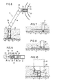
- FIG. 1 to 4 the construction of a construction system is shown schematically. Zünachst a shallow excavation pit 1 is created and possibly supported with retaining walls 2. The bottom of the excavation pit 1 forms the base 3 for the foundation body 4.
- a single foundation plate for example, is sufficient for setting up a rod, while accessible and crawlable construction systems may require a larger number of foundation bodies 4.
- a template 5 can be used for laying the fun dam body 4, as shown schematically in Fig. 1, a template 5 can be used.
- the foundation body 4 is covered with a network or grid 6, which, however, protrude beyond the surface of the foundation body 4.
- a grating made of bar iron is suitable as a grating.
- a blanket 7 is spread out on the grid, which also projects beyond the surface of the foundation body 4, see FIG. 2. Both the grid 6 and the blanket 7, but also only the blanket 7, can be placed on the foundation body 4.
- Column members 8 are now fastened to the foundation bodies 4, see FIG. 3.
- the column member 8 is part of a one-part or multi-part support element 11, which will be described in detail below.
- the construction pit 1 is filled with a pourable material 9, which has the task of acting as a damping layer for the mediation of accidents.
- a pourable material 9 which has the task of acting as a damping layer for the mediation of accidents.
- the material 9 forms an additional weight for loading the foundation body 4.
- FIG. 4 shows as a final stage the support of a foundation element 10 of a construction system by means of two support elements 11. Depending on the size of the planned construction system, further foundation elements are supported in the excavation pit, on which the entire construction system is then built.
- the construction can be carried out in exactly the same way in a tub delimited by a wall.
- the floor then forms the base 3 for the foundation body 4.
- the laying of the foundation body 4 and the ceiling 7 with or without a grid 6, the insertion of the column members 8 and the filling of the material 9 are carried out in the same way as when using an excavation pit 1.
- such a material layer 9 is used in all construction positions. This can expediently have a thickness of 200-600 mm.
- the support of the foundation element 10 according to FIG. 4 is shown enlarged in FIG. 5.
- the two foundation bodies 4 are composed of a foundation plate 12 and a holder 15 fastened on the upper side of the foundation plate 12.
- the holder 15 is designed as a pipe socket in Fig. 5, but it can also have a different shape, e.g. of a massive body.
- the holder 15 serves to fasten the column member 8, which in FIG. 5 is positively connected to the holder 15 by means of fastening bolts 16.
- the other end of the column member 8 has a connecting member 17, which enables the coupling of the column member 8 to a connecting joint 18, which will be described in detail with reference to FIG. 9.
- the connecting joint 18 is connected via a connecting member 17 to a fastening member 19 carrying the foundation element 10.
- the fastening member 19 is a tube extending through the foundation element 10, in which a connecting member 17 is arranged at both ends as in the case of the column member 8.
- FIG. 6 shows one side of a support of a foundation element 10 arranged freely above the material 9 by means of a support element 11 which is composed of several links.
- the column member 8 is fastened with fastening bolts 16.
- a connecting joint 18 is coupled to the connecting member 17 of the column member 8, to which a further column member 8 connects, which is coupled to a further connecting joint 18.
- the further connecting joint 18 is coupled to a connecting member 17, which is connected to a fastening member 19, the latter of which protrudes into a fastening recess of the foundation element 10 and is held there in a form-fitting manner with a clamping bolt 21.
- the support element 11 thus forms a positive connection between the foundation element 10 and the foundation body 4 covered by the material 9.
- Another identical support element 11 is arranged in a mirror image of the central axis of the foundation element 10 (not shown).
- FIG. 7 the column member 8 is designed as a full rod, in which a threaded pin 22 is arranged at one end and the other end as a connecting member 17 for coupling with a connecting joint 18 is formed.
- the threaded pin 22 is screwed into a threaded insert 23 which is inserted in the foundation plate 12, which can be designed, for example, as a reinforced concrete plate.
- the ceiling 7 extends over the surface of the foundation plate 12.
- the foundation plate 12 is a solid plate made of metal, e.g. made of cast iron or steel, on the top of which a pin 24 is fastened with an internal thread, e.g. is welded on.
- the threaded pin 22 of the column member 8 is screwed into the internal thread.
- a connecting element 11 is shown in detail, which is composed of two similar joint parts 31, 32.
- Each joint part 31, 32 has a hemisphere 33 to which a hollow body 34 in the form of a half cylinder connects. If this hollow body is screwed together with another hollow body 35 in the form of a half cylinder, a coupling part is produced which can be coupled, for example, to a connecting member 17 of a column member 8 or a fastening member 19.
- the two hollow bodies 34, 35 are provided with an inner flange 37 at their free end.
- a corresponding groove 38 is to be provided on the connecting member 17 of the column member 8 or of the fastening member 19.
- webs can be provided in the inner flange 37 and in the groove 38, which, when the two hollow bodies 34, 35 are screwed together, result in an exact positional fixation in the circumferential direction by means of screw bolts.
- a further positional fixation between the two hemispheres 33 is achieved in that the support surfaces are provided with serration 39. If the two hemispheres 33 are locked in the correct position, they are firmly pulled together by a screw bolt with a nut 40, 41.
- the foundation element 10 is a vertically standing pipe which is connected to an end piece 45, which enables the support of this vertically standing foundation element with the foundation body 4.
- a connecting member 46 in the form of a disc is fixedly arranged on the column member 8, which is connected to the holder 15 by means of fastening bolts 16 in the same way as in FIGS. 5 and 6, on which the end piece 45 is supported and fastened with screw bolts 47 is.
- Construction site 50 is accessible via a ladder section A, to which a central section B and a pipe section C are connected with an exit to the outside.
- the foundation bodies used in the construction system 50 are designated by F, supporting elements 11 according to FIG. 10 being used in the conductor part A, supporting elements 11 according to FIG. 6 in the central part B and supporting element 11 according to FIG. 5 in the tubular part C.
- a total of 10 support bodies are arranged, which ensure great stability for the construction system 50.
- FIGS. 12 and 13 The construction system shown in FIGS. 12 and 13 is built on the same foundation bodies F with the same spatial arrangement. This shows how a construction system can easily be replaced by a set of other components. The replacement can be carried out with relatively little effort and without difficulty.
- a large number of different construction systems can therefore be set up on a single foundation body grouping.
- the transition to a new foundation body grouping with a different number of different construction systems can also be carried out relatively easily.
- the material 9 must be removed at least partially, whereupon the foundation body 4 is then brought into its new position.
- the ceiling 7 with or without the grid 6 is then re-installed and the material 9 is reintroduced.
- tubular and shell-shaped components shown in Figures 10 to 14 are not shown in detail. They can be double-walled as in FIGS. 5 and 6 and then correspond to the design of the components according to the EP, patents mentioned at the beginning. Depending on the intended use, the interior space between the walls can remain empty or be filled with a pressure medium or a solid material. For this purpose, reference is made to the two EP patents mentioned at the beginning.
- the construction system according to the invention has various advantages: thanks to the sufficient number of foundation bodies 4 that can be used in each case, the construction system has great stability, which is further reinforced by the material 9 piled onto the ceiling 7.
- the large area of the foundation plate 12 does not require a high compressive strength of the base 3.
- the form-fitting connection of the support element 11 such a construction system offers great security of use.
- high mechanical strength, simple and quick assembly and disassembly, low susceptibility to faults and good protection of the connections between the foundation body 4 and support elements 11 are also guaranteed.
- the foundation body 4 can also be used for the construction of construction systems in which other components are used are considered as those under the two patents mentioned. It is only necessary to ensure a reliable connection between these components on the one hand and between the components and the support elements on the other.
Landscapes
- Engineering & Computer Science (AREA)
- Civil Engineering (AREA)
- Structural Engineering (AREA)
- Life Sciences & Earth Sciences (AREA)
- General Health & Medical Sciences (AREA)
- General Life Sciences & Earth Sciences (AREA)
- Mining & Mineral Resources (AREA)
- Paleontology (AREA)
- Health & Medical Sciences (AREA)
- Physical Education & Sports Medicine (AREA)
- General Engineering & Computer Science (AREA)
- Joining Of Building Structures In Genera (AREA)
- Building Environments (AREA)
- Revetment (AREA)
- Underground Structures, Protecting, Testing And Restoring Foundations (AREA)
- Conveying And Assembling Of Building Elements In Situ (AREA)
- Foundations (AREA)
- Buildings Adapted To Withstand Abnormal External Influences (AREA)
Claims (8)
Priority Applications (1)
| Application Number | Priority Date | Filing Date | Title |
|---|---|---|---|
| AT86101301T ATE56772T1 (de) | 1985-03-04 | 1986-01-31 | Bauanlage aus mehreren bauelementen. |
Applications Claiming Priority (2)
| Application Number | Priority Date | Filing Date | Title |
|---|---|---|---|
| CH969/85A CH670278A5 (fr) | 1985-03-04 | 1985-03-04 | |
| CH969/85 | 1985-03-04 |
Publications (3)
| Publication Number | Publication Date |
|---|---|
| EP0193737A2 EP0193737A2 (fr) | 1986-09-10 |
| EP0193737A3 EP0193737A3 (en) | 1987-12-09 |
| EP0193737B1 true EP0193737B1 (fr) | 1990-09-19 |
Family
ID=4199409
Family Applications (1)
| Application Number | Title | Priority Date | Filing Date |
|---|---|---|---|
| EP86101301A Expired - Lifetime EP0193737B1 (fr) | 1985-03-04 | 1986-01-31 | Construction en plusieurs éléments |
Country Status (5)
| Country | Link |
|---|---|
| EP (1) | EP0193737B1 (fr) |
| AT (1) | ATE56772T1 (fr) |
| CH (1) | CH670278A5 (fr) |
| DE (1) | DE3674225D1 (fr) |
| ES (1) | ES8700712A1 (fr) |
Family Cites Families (8)
| Publication number | Priority date | Publication date | Assignee | Title |
|---|---|---|---|---|
| US2944815A (en) * | 1958-03-06 | 1960-07-12 | Austin S Moyer | Mounting of gymnastic equipment |
| GB1138339A (en) * | 1965-12-28 | 1969-01-01 | Geoffrey William Thomas | Support apparatus, particularly but not exclusively for games posts |
| GB1342624A (en) * | 1972-05-31 | 1974-01-03 | Lewington B H | Amusement or exercise device |
| FR2198382A5 (fr) * | 1972-08-30 | 1974-03-29 | Gesret Pierre | |
| US3837641A (en) * | 1973-02-02 | 1974-09-24 | C Hanson | Rotatable swing bar |
| US3840203A (en) * | 1973-08-17 | 1974-10-08 | F Sheehy | Base plate for outdoor gym sets |
| BE815567A (fr) * | 1974-05-27 | 1974-09-16 | Structures pour l'amenagement de plaines de jeux et jardins. | |
| GB1526769A (en) * | 1976-11-30 | 1978-09-27 | Staines Metal Prod Ltd | Below ground clamp unit |
-
1985
- 1985-03-04 CH CH969/85A patent/CH670278A5/de not_active IP Right Cessation
-
1986
- 1986-01-31 EP EP86101301A patent/EP0193737B1/fr not_active Expired - Lifetime
- 1986-01-31 DE DE8686101301T patent/DE3674225D1/de not_active Expired - Fee Related
- 1986-01-31 AT AT86101301T patent/ATE56772T1/de active
- 1986-02-24 ES ES552310A patent/ES8700712A1/es not_active Expired
Also Published As
| Publication number | Publication date |
|---|---|
| EP0193737A2 (fr) | 1986-09-10 |
| DE3674225D1 (de) | 1990-10-25 |
| EP0193737A3 (en) | 1987-12-09 |
| ATE56772T1 (de) | 1990-10-15 |
| CH670278A5 (fr) | 1989-05-31 |
| ES552310A0 (es) | 1986-11-16 |
| ES8700712A1 (es) | 1986-11-16 |
Similar Documents
| Publication | Publication Date | Title |
|---|---|---|
| DE1903129C3 (de) | Vorrichtung zum Anschließen eines Trägers an eine Betonstütze | |
| DE3224986C2 (de) | Vorrichtung zur Befestigung von Montageteilen an einer Betonwand | |
| EP0013570A1 (fr) | Système de plancher surélevé | |
| CH642701A5 (de) | Fahrbahndecke aus einzelnen, miteinander verbundenen elementen. | |
| DE4234892C2 (de) | Anordnung zum lage- und richtungsstabilen Einbau von Verankerungsteilen in Beton | |
| DE2717645A1 (de) | Baukastensystem zur erstellung von baenken, tischen o.dgl. | |
| DE9409626U1 (de) | Balkonkonstruktion | |
| DE2732183B2 (de) | Verbindung zweier mit ihren Stirnflächen einander gegenüberliegenden Stahlbetonteile | |
| DE2836863A1 (de) | Tragstruktur mit vorgefertigten vertikalen und horizontalen elementen, die pfeiler bzw. deckenplatten bilden | |
| EP0193737A2 (fr) | Construction en plusieurs éléments | |
| EP4194613A1 (fr) | Module de fabrication d'une fondation en béton, utilisation et procédé | |
| DE4238181A1 (en) | Mounting for communications mast, e.g. for traffic signal unit - has tubes set in concrete and receiving fixing bolts tightened to spread elements and grip inner surface. | |
| DE1993198U (de) | Bauelementensatz fuer einen begehbaren hohlboden. | |
| DE1778050C3 (de) | Leicht aus Bauteilen zusammensetzbare, steife, kastenartige Rahmenkonstruktion für Gestelle, Schränke od.dgl | |
| DE3718056A1 (de) | Verbindungsvorrichtung fuer grabmaeler und bauwerke aehnlicher ausbildung | |
| DE202008011282U1 (de) | Sockel für einen Roboter | |
| DE3306182A1 (de) | Saeulenfuss | |
| DE9200115U1 (de) | Verankerungsvorrichtung zur Bodenverankerung von Masten, insbesondere von Verkehrssignalanlagen | |
| DE2529506A1 (de) | Stahlbetonfertigteilsystem zur herstellung von ein- und mehrreihigen zellensilos | |
| DE1659717C (de) | Tragkonstruktion fur einen Treppen lauf | |
| DE3148219C2 (de) | Hilfsvorrichtung zum Herstellen eines teilweise von Ortbeton umgebenen Widerlagers für Gebäudedächer | |
| DE7635823U1 (de) | Bausatz fuer gebaeude | |
| DE4415446A1 (de) | Verbindung eines Bodenankers mit einem Ständer | |
| DE2531251B2 (de) | Verfahren zur Herstellung einer künstlichen Insel | |
| DE3443269A1 (de) | Wandelement |
Legal Events
| Date | Code | Title | Description |
|---|---|---|---|
| PUAI | Public reference made under article 153(3) epc to a published international application that has entered the european phase |
Free format text: ORIGINAL CODE: 0009012 |
|
| AK | Designated contracting states |
Kind code of ref document: A2 Designated state(s): AT BE DE FR GB IT LU NL SE |
|
| PUAL | Search report despatched |
Free format text: ORIGINAL CODE: 0009013 |
|
| AK | Designated contracting states |
Kind code of ref document: A3 Designated state(s): AT BE DE FR GB IT LU NL SE |
|
| 17P | Request for examination filed |
Effective date: 19880509 |
|
| 17Q | First examination report despatched |
Effective date: 19890522 |
|
| GRAA | (expected) grant |
Free format text: ORIGINAL CODE: 0009210 |
|
| AK | Designated contracting states |
Kind code of ref document: B1 Designated state(s): AT BE DE FR GB IT LU NL SE |
|
| REF | Corresponds to: |
Ref document number: 56772 Country of ref document: AT Date of ref document: 19901015 Kind code of ref document: T |
|
| ITF | It: translation for a ep patent filed | ||
| REF | Corresponds to: |
Ref document number: 3674225 Country of ref document: DE Date of ref document: 19901025 |
|
| ET | Fr: translation filed | ||
| GBT | Gb: translation of ep patent filed (gb section 77(6)(a)/1977) | ||
| ITTA | It: last paid annual fee | ||
| PLBE | No opposition filed within time limit |
Free format text: ORIGINAL CODE: 0009261 |
|
| STAA | Information on the status of an ep patent application or granted ep patent |
Free format text: STATUS: NO OPPOSITION FILED WITHIN TIME LIMIT |
|
| 26N | No opposition filed | ||
| EPTA | Lu: last paid annual fee | ||
| EAL | Se: european patent in force in sweden |
Ref document number: 86101301.9 |
|
| PGFP | Annual fee paid to national office [announced via postgrant information from national office to epo] |
Ref country code: AT Payment date: 19990625 Year of fee payment: 14 Ref country code: LU Payment date: 19990625 Year of fee payment: 14 |
|
| PGFP | Annual fee paid to national office [announced via postgrant information from national office to epo] |
Ref country code: DE Payment date: 19990626 Year of fee payment: 14 |
|
| PGFP | Annual fee paid to national office [announced via postgrant information from national office to epo] |
Ref country code: SE Payment date: 19990628 Year of fee payment: 14 |
|
| PG25 | Lapsed in a contracting state [announced via postgrant information from national office to epo] |
Ref country code: AT Free format text: LAPSE BECAUSE OF NON-PAYMENT OF DUE FEES Effective date: 20000131 Ref country code: LU Free format text: LAPSE BECAUSE OF NON-PAYMENT OF DUE FEES Effective date: 20000131 |
|
| PG25 | Lapsed in a contracting state [announced via postgrant information from national office to epo] |
Ref country code: SE Free format text: LAPSE BECAUSE OF NON-PAYMENT OF DUE FEES Effective date: 20000201 |
|
| EUG | Se: european patent has lapsed |
Ref document number: 86101301.9 |
|
| PG25 | Lapsed in a contracting state [announced via postgrant information from national office to epo] |
Ref country code: DE Free format text: LAPSE BECAUSE OF NON-PAYMENT OF DUE FEES Effective date: 20001101 |
|
| NLS | Nl: assignments of ep-patents |
Owner name: LUDOPARC SA |
|
| REG | Reference to a national code |
Ref country code: GB Ref legal event code: 732E |
|
| REG | Reference to a national code |
Ref country code: FR Ref legal event code: TP |
|
| REG | Reference to a national code |
Ref country code: GB Ref legal event code: IF02 |
|
| PGFP | Annual fee paid to national office [announced via postgrant information from national office to epo] |
Ref country code: FR Payment date: 20041130 Year of fee payment: 20 |
|
| PGFP | Annual fee paid to national office [announced via postgrant information from national office to epo] |
Ref country code: NL Payment date: 20041231 Year of fee payment: 20 |
|
| PGFP | Annual fee paid to national office [announced via postgrant information from national office to epo] |
Ref country code: IT Payment date: 20050114 Year of fee payment: 20 |
|
| PGFP | Annual fee paid to national office [announced via postgrant information from national office to epo] |
Ref country code: GB Payment date: 20050125 Year of fee payment: 20 |
|
| PGFP | Annual fee paid to national office [announced via postgrant information from national office to epo] |
Ref country code: BE Payment date: 20050217 Year of fee payment: 20 |
|
| REG | Reference to a national code |
Ref country code: GB Ref legal event code: PE20 |
|
| PG25 | Lapsed in a contracting state [announced via postgrant information from national office to epo] |
Ref country code: GB Free format text: LAPSE BECAUSE OF EXPIRATION OF PROTECTION Effective date: 20060130 |
|
| PG25 | Lapsed in a contracting state [announced via postgrant information from national office to epo] |
Ref country code: NL Free format text: LAPSE BECAUSE OF EXPIRATION OF PROTECTION Effective date: 20060131 |
|
| NLV7 | Nl: ceased due to reaching the maximum lifetime of a patent |
Effective date: 20060131 |
|
| BE20 | Be: patent expired |
Owner name: S.A. *LUDOPARC Effective date: 20060131 |