EP0193742A2 - Interférométrie avec une longueur d'ondes variable et interféromètre avec diode à laser - Google Patents
Interférométrie avec une longueur d'ondes variable et interféromètre avec diode à laser Download PDFInfo
- Publication number
- EP0193742A2 EP0193742A2 EP86101421A EP86101421A EP0193742A2 EP 0193742 A2 EP0193742 A2 EP 0193742A2 EP 86101421 A EP86101421 A EP 86101421A EP 86101421 A EP86101421 A EP 86101421A EP 0193742 A2 EP0193742 A2 EP 0193742A2
- Authority
- EP
- European Patent Office
- Prior art keywords
- laser diode
- photosensor
- wavelength
- interference pattern
- scanning type
- Prior art date
- Legal status (The legal status is an assumption and is not a legal conclusion. Google has not performed a legal analysis and makes no representation as to the accuracy of the status listed.)
- Granted
Links
- 238000005305 interferometry Methods 0.000 title claims abstract description 9
- 238000002347 injection Methods 0.000 claims abstract description 14
- 239000007924 injection Substances 0.000 claims abstract description 14
- 230000003287 optical effect Effects 0.000 description 20
- 238000010586 diagram Methods 0.000 description 13
- 238000000034 method Methods 0.000 description 7
- 238000007689 inspection Methods 0.000 description 3
- 238000005259 measurement Methods 0.000 description 3
- 238000012545 processing Methods 0.000 description 3
- 230000004075 alteration Effects 0.000 description 1
- 238000012937 correction Methods 0.000 description 1
- 238000013461 design Methods 0.000 description 1
- 230000014509 gene expression Effects 0.000 description 1
- 238000012544 monitoring process Methods 0.000 description 1
- 230000010363 phase shift Effects 0.000 description 1
- 238000003672 processing method Methods 0.000 description 1
- 239000004065 semiconductor Substances 0.000 description 1
- 239000000758 substrate Substances 0.000 description 1
Images



Classifications
-
- G—PHYSICS
- G01—MEASURING; TESTING
- G01J—MEASUREMENT OF INTENSITY, VELOCITY, SPECTRAL CONTENT, POLARISATION, PHASE OR PULSE CHARACTERISTICS OF INFRARED, VISIBLE OR ULTRAVIOLET LIGHT; COLORIMETRY; RADIATION PYROMETRY
- G01J9/00—Measuring optical phase difference; Determining degree of coherence; Measuring optical wavelength
- G01J9/04—Measuring optical phase difference; Determining degree of coherence; Measuring optical wavelength by beating two waves of a same source but of different frequency and measuring the phase shift of the lower frequency obtained
-
- G—PHYSICS
- G01—MEASURING; TESTING
- G01J—MEASUREMENT OF INTENSITY, VELOCITY, SPECTRAL CONTENT, POLARISATION, PHASE OR PULSE CHARACTERISTICS OF INFRARED, VISIBLE OR ULTRAVIOLET LIGHT; COLORIMETRY; RADIATION PYROMETRY
- G01J3/00—Spectrometry; Spectrophotometry; Monochromators; Measuring colours
- G01J3/28—Investigating the spectrum
- G01J3/45—Interferometric spectrometry
Definitions
- the present invention relates to an optical interferometry and interferometer utilizing the interference phenomenon of laser beams. More particularly, it relates to a wavelength scanning interferometry and interferometer with a laser diode that are well-suited for application to, e. g., the inspection of optical elements of which a high precision is required for reading an interference pattern.
- the wavelength of a light source is fixed, and such a method as, for example, providing one of beams with a frequency shifter or modulating the phase of light by means of a piezoelectric device is employed for raising the reading precision of an interference pattern.
- a method as, for example, providing one of beams with a frequency shifter or modulating the phase of light by means of a piezoelectric device is employed for raising the reading precision of an interference pattern.
- both the devices are expensive.
- Other disadvantages are that a large number of portions must be adjusted and that a driving power source of high voltage is required.
- the wavelength of a light source is fixed.
- a method is employed in which the wavelength of one of beams is shifted by a frequency modulator or in which a piezoelectric device is mounted on a mirror so as to perform phase modulation.
- Both the methods are disadvantageous in that the modulation devices are expensive and require high voltages. The latter.method involves complicated handling for the corrections of nonlinearity and hysteresis, etc.
- An object of the present invention is to eliminate the disadvantages described above, and to provide a laser diode interferometer which is inexpensive and simple and is easy of manipulation and which permits to electrically read an interference pattern and to perform interference pattern processing at high precision.
- the present invention consists in that a laser diode is employed as the light source of an interferometer of the Fizeau type, the Michelson type, the Twyman-Green type, the Mach-Zehnder type or the like and that the drive current of the laser diode is modulated to scan the wavelength thereof, thereby to scan an interference pattern and to enhance the reading precision of the interference pattern. That is, with note taken of the unstable characteristic of a laser diode that the wavelength thereof changes delicately depending upon the amount of current applied, the present invention consists in that the wavelength of the laser diode itself is changed by utilizing the characteristic contrariwise. According to the present invention, the whole apparatus is miniaturized. The accuracy can be raised double or more, and the required power can be lowered to one thousandth.
- the present invention can measure a lens, a mirror etc. and also the front of the light wave of a laser source, and is extensively applicable to. the design of laser devices, etc.
- the quantity of light having fluctuated due to the change of the drive current of a laser diode is monitored, and the fluctuation of the intensity distribution of an interference pattern is normalized, to perform electric processing of higher precision.
- the shift magnitude ⁇ of the wavelength is given by:
- the complex amplitude of light at an arbitrary point (x, y) on an interference pattern is given on the time average by:
- u 0 and u r denote the amplitudes of an object beam and a reference beam respectively
- r 0 and r r denote the optical lengths of the object beam and the reference beam from a reference plane respectively
- k denotes a wave number which is given by:
- an interference pattern which has the maximum intensity at a point (x, y) satisfying and the minimum intensity at a. point satisfying
- the intensity distribution I(x, y) is:
- ⁇ (x, y) is the phase of a wavefront to be measured, and is the optical path difference at the point (x, y).
- the wavelength ⁇ of the laser diode fluctuates when the injection current i is changed.
- the wavelength slightly shifts ( ⁇ ) as:
- phase ⁇ of the foregoing wavefront can be written as: ⁇ 0 denotes the initial wavelength.
- phase shift ⁇ is: and Eq. (6) is given for a shift of 2 ⁇ .
- Eq. (9) gives the current change ⁇ i for shifting the interference pattern by one fringe in the interferometer of the optical length difference l.
- Fig. 1 illustrates this relationship graphically.
- the difference of optical lengths is 10 cm
- the operating median of a diode laser is usually 60 - 100 mA as illustrated in Fig. 2. It is therefore understood that the wavelength scanning is possible with a very slight current modulation. In addition, the change of the light output is very slight for such a current change.
- the second point of the present invention consists in obtaining the normalized interference pattern intensity distribution as in the following equation: by monitoring the quantity of light I 0 of the laser diode and dividing the photocurrent I P by the monitored current. That is, dividers are connected to the respective elements of the CCD.
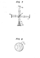
- Fig. 6 is a setup diagram showing an embodiment of the present invention, and illustrates the case of a Mach-Zehnder type interferometer.
- This interferometer employs a laser diode 1 as a light source. A light beam from this diode laser is turned by a condenser lens 2 into a collimated beam, which is split into two beams by a beam splitter 3-1.
- One of the beams is used as a beam for inspection, in which a transmissive object 10 to be measured is placed and which is reflected by a reflector mirror 4-2 and is combined via a second beam splitter 3-2 with the other beam (reference beam) from a reflector mirror 4-1 to form an interference pattern on a photodetector 6 of a two-dimensional photosensor array (CCD).
- the difference between the optical lengths of the two beams can be adjusted by rotating the beam splitter 3-1 and moving the reflector mirror 4-1.
- Fig. 7 is a setup diagram showing another embodiment of the present invention, in which the invention is applied to a Twyman-Green type interferometer.
- a beam from a light source constructed of a laser diode 1 is turned by a condenser lens 2 into a colliminated beam, which is split into two beams by a beam splitter 3.
- One of the beams to serve as a reference beam is reflected by a reflector mirror 4, and is transmitted through the beam splitter 3 to fall on a photodetector (CCD) 6.
- CCD photodetector
- the beam transmitted through the beam splitter 3 is employed as an inspection beam.
- This beam is reflected by an object to-be-inspected 10 and is further reflected by the beam splitter 3, to form an interference pattern on the photodetector (CCD) 6 conjointly with the reference beam.
- CCD photodetector
- Fig. 8 is a diagram showing an example of the interference pattern obtained with this interferometer.
- the spacing between interferaice fringes L l (indicated by a solid line) and L 2 (indicated by a dotted line) corresponds to the shift of a wavefront equal to one wavelength.
- the interference fringe L appears for the wavelength ⁇ 1 and that L 2 appears for the wavelength ⁇ 2 , so that the interference fringe moves.
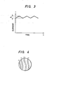
- the current of the laser diode 1 is modulated by a triangular wave of frequency ⁇ and amplitude ⁇ i as shown in Fig.
- the resulting signal is passed through a filter which has a pass frequency f given by Eq. (II), whereby only the frequency component can be extracted as a signal of high signal-to-noise ratio. That is, an oscillating component attributed to the disturbance of the interferometer and the influences of temperature etc. can be eliminated, and the reading precision can be enhanced by repeating measurements a large number of times and irregularly and taking an average. Further, a phase distribution after the error and inclination of the interferometer itself, the error of focusing, etc. have been subtracted can be displayed by a contour map or the like.
- Fig. 9(a) is a circuit diagram showing an embodiment of a laser diode driver circuit for use in the present invention, while Fig. 9(b) is a signal waveform diagram thereof.
- This circuit serves to modulate the semiconductor laser or laser didode LD (corresponding to the laser 1 in Figs. 6 and 7) with an amplitude ⁇ i having a center value at a bias current i o .
- a voltage of -V E volts is applied to a point A in the figure and a potential at a point B (the base of a transistor Q) is set to -V B volts by a variable resistor R 1
- the current of this value is used as the bias current.
- the current modulation whose amplitude is ⁇ i is performed in such a way that a triangular wave of frequency ⁇ as shown in Fig. 9(b) is externally input to a point C in the figure, and that the laser diode is driven by this modulating current.
- the light output of the laser diode changes when the injection current changes. Therefore, the light output of the laser diode 1 is monitored by means of a photodetector 8 disposed in a laser module, and the interference pattern intensity is normalized with the output thereof.
- FIG. 10 A practical divider circuit therefor is shown in Fig. 10.
- a photocurrent based on the interference pattern intensity (the output of each element of the CCD 6) is input to the numerator Z of a divider commercially available, AD532 (manufactured by Analog Device Inc.), while a photocurrent derived from a light output behind the laser diode (the output of the photodetector 8) is input to the denominator X, thereby to perform the following division:
- the normalized interference pattern signal Eq. (13)
- a signal from any element 6-1 of the CCD is input to the input terminal Z of the divider AD532 through an amplifier 11.
- the D.C. output light of the laser diode is received by the photodetector 8 and is input to the input terminal X of the divider 14 via two stages of amplifiers 12 and 13.
- an output signal Out is obtained: When this signal is multiplied by -10, namely, in Eq. (13) is obtained.
- the reading of an interference pattern at high precision is permitted merely by modulating the drive current of a laser-diode light source slightly.
- the interference scanning can be carried out without a piezoelectric device or a frequency shifter.
Landscapes
- Physics & Mathematics (AREA)
- Spectroscopy & Molecular Physics (AREA)
- General Physics & Mathematics (AREA)
- Instruments For Measurement Of Length By Optical Means (AREA)
Applications Claiming Priority (2)
| Application Number | Priority Date | Filing Date | Title |
|---|---|---|---|
| JP42642/85 | 1985-03-06 | ||
| JP60042642A JPS61202128A (ja) | 1985-03-06 | 1985-03-06 | 半導体レ−ザヘテロダイン干渉計 |
Publications (3)
| Publication Number | Publication Date |
|---|---|
| EP0193742A2 true EP0193742A2 (fr) | 1986-09-10 |
| EP0193742A3 EP0193742A3 (en) | 1988-08-03 |
| EP0193742B1 EP0193742B1 (fr) | 1991-10-23 |
Family
ID=12641667
Family Applications (1)
| Application Number | Title | Priority Date | Filing Date |
|---|---|---|---|
| EP86101421A Expired EP0193742B1 (fr) | 1985-03-06 | 1986-02-04 | Interférométrie avec une longueur d'ondes variable et interféromètre avec diode à laser |
Country Status (4)
| Country | Link |
|---|---|
| US (1) | US4759628A (fr) |
| EP (1) | EP0193742B1 (fr) |
| JP (1) | JPS61202128A (fr) |
| DE (1) | DE3682085D1 (fr) |
Cited By (5)
| Publication number | Priority date | Publication date | Assignee | Title |
|---|---|---|---|---|
| GB2192454A (en) * | 1986-07-01 | 1988-01-13 | Intellemetrics Limited | System for measuring optical coatings |
| EP0277883A3 (fr) * | 1987-02-03 | 1991-01-02 | Fujitsu Limited | Dispositif de déflexion holographique |
| GB2271632A (en) * | 1992-10-19 | 1994-04-20 | Tabarelli Werner | Frequency modulated interferometer |
| EP0629851A3 (fr) * | 1993-06-17 | 1995-03-22 | Fraunhofer Ges Forschung | Dispositif pour analyse de traces de gaz par spectroscopie d'absorption. |
| EP0916938A3 (fr) * | 1997-11-13 | 1999-10-13 | Biophotonics Information Laboratories Ltd. | Appareil de mesure optique |
Families Citing this family (22)
| Publication number | Priority date | Publication date | Assignee | Title |
|---|---|---|---|---|
| US5151752A (en) * | 1988-06-16 | 1992-09-29 | Asahi Kogaku Kogyo K.K. | Method of measuring refractive indices of lens and sample liquid |
| JPH0222502A (ja) * | 1988-07-11 | 1990-01-25 | Kowa Co | 光干渉測定装置 |
| US4886363A (en) * | 1988-09-06 | 1989-12-12 | Eastman Kodak Company | Quadratic frequency modulated absolute distance measuring interferometry |
| US5157459A (en) * | 1989-08-29 | 1992-10-20 | Asahi Kogaku Kogyo Kabushiki Kaisha | Wave front aberration measuring apparatus |
| US5110211A (en) * | 1990-01-04 | 1992-05-05 | Shoji Niki | Optical interference signal extractor with device for reduced noise from optical light power variation |
| US5096296A (en) * | 1990-07-24 | 1992-03-17 | Canadian Marconi Company | Method for measuring optical path difference of an imbalanced interferometer in a system |
| US5128797A (en) * | 1991-02-11 | 1992-07-07 | The United States Of America As Represented By The Administrator Of The National Aeronautics And Space Administration | Non-mechanical optical path switching and its application to dual beam spectroscopy including gas filter correlation radiometry |
| US5196350A (en) * | 1991-05-29 | 1993-03-23 | Omnigene, Inc. | Ligand assay using interference modulation |
| JP3264469B2 (ja) * | 1993-12-07 | 2002-03-11 | 富士写真フイルム株式会社 | 光散乱媒体の屈折率分布情報の計測装置 |
| JP3287517B2 (ja) * | 1994-06-29 | 2002-06-04 | 富士写真光機株式会社 | 干渉縞による測定方法および装置 |
| US6057923A (en) * | 1998-04-20 | 2000-05-02 | The United States Of America As Represented By The Administrator Of The National Aeronautics And Space Administration | Optical path switching based differential absorption radiometry for substance detection |
| JP4536873B2 (ja) * | 2000-06-05 | 2010-09-01 | キヤノン株式会社 | 三次元形状計測方法及び装置 |
| GB0600036D0 (en) * | 2006-01-04 | 2006-02-08 | Ibm | System and method for finding integer solutions |
| CA2766169A1 (fr) * | 2009-07-24 | 2011-01-27 | Bobst Sa | Dispositif de topographie d'une surface d'un substrat |
| US9052497B2 (en) | 2011-03-10 | 2015-06-09 | King Abdulaziz City For Science And Technology | Computing imaging data using intensity correlation interferometry |
| US9099214B2 (en) | 2011-04-19 | 2015-08-04 | King Abdulaziz City For Science And Technology | Controlling microparticles through a light field having controllable intensity and periodicity of maxima thereof |
| KR101358091B1 (ko) * | 2012-01-11 | 2014-02-06 | 주식회사 고영테크놀러지 | 간섭계 및 이를 이용한 광학장치 |
| US9459155B2 (en) * | 2012-09-27 | 2016-10-04 | National University Corporation Hokkaido University | Method for measuring optical phase, device for measuring optical phase, and optical communication device |
| US9341516B2 (en) | 2013-08-30 | 2016-05-17 | Agilent Technologies, Inc. | System for performing optical spectroscopy including interferometer |
| US11515681B2 (en) * | 2018-07-12 | 2022-11-29 | Electronics And Telecommunications Research Institute | Laser module and laser system including the same |
| KR102810332B1 (ko) * | 2018-07-12 | 2025-05-27 | 한국전자통신연구원 | 레이저 모듈 및 그를 포함하는 레이저 시스템 |
| US11283237B2 (en) * | 2019-07-22 | 2022-03-22 | Coherent, Inc. | Laser wavelength stabilization apparatus |
Family Cites Families (5)
| Publication number | Priority date | Publication date | Assignee | Title |
|---|---|---|---|---|
| US3635562A (en) * | 1968-11-12 | 1972-01-18 | Comp Generale Electricite | Optical interferometer for detection of small displacements |
| US3805074A (en) * | 1973-01-02 | 1974-04-16 | Texas Instruments Inc | Spectral scan air monitor |
| JPS5487588A (en) * | 1977-12-24 | 1979-07-12 | Fujitsu Ltd | Infrared spectral analytical apparatus |
| FR2517839A1 (fr) * | 1981-12-07 | 1983-06-10 | Thomson Csf | Dispositif de detection heterodyne d'une image optique |
| US4594003A (en) * | 1983-07-20 | 1986-06-10 | Zygo Corporation | Interferometric wavefront measurement |
-
1985
- 1985-03-06 JP JP60042642A patent/JPS61202128A/ja active Pending
-
1986
- 1986-02-04 DE DE8686101421T patent/DE3682085D1/de not_active Expired - Lifetime
- 1986-02-04 EP EP86101421A patent/EP0193742B1/fr not_active Expired
- 1986-02-05 US US06/826,341 patent/US4759628A/en not_active Expired - Fee Related
Cited By (7)
| Publication number | Priority date | Publication date | Assignee | Title |
|---|---|---|---|---|
| GB2192454A (en) * | 1986-07-01 | 1988-01-13 | Intellemetrics Limited | System for measuring optical coatings |
| EP0277883A3 (fr) * | 1987-02-03 | 1991-01-02 | Fujitsu Limited | Dispositif de déflexion holographique |
| GB2271632A (en) * | 1992-10-19 | 1994-04-20 | Tabarelli Werner | Frequency modulated interferometer |
| US5539520A (en) * | 1992-10-19 | 1996-07-23 | Dr. Johannes Heidenhain Gmbh | Interferometer using frequency modulation of the carrier frequency |
| GB2271632B (en) * | 1992-10-19 | 1996-07-24 | Tabarelli Werner | Interferometric device |
| EP0629851A3 (fr) * | 1993-06-17 | 1995-03-22 | Fraunhofer Ges Forschung | Dispositif pour analyse de traces de gaz par spectroscopie d'absorption. |
| EP0916938A3 (fr) * | 1997-11-13 | 1999-10-13 | Biophotonics Information Laboratories Ltd. | Appareil de mesure optique |
Also Published As
| Publication number | Publication date |
|---|---|
| EP0193742B1 (fr) | 1991-10-23 |
| DE3682085D1 (de) | 1991-11-28 |
| EP0193742A3 (en) | 1988-08-03 |
| JPS61202128A (ja) | 1986-09-06 |
| US4759628A (en) | 1988-07-26 |
Similar Documents
| Publication | Publication Date | Title |
|---|---|---|
| EP0193742B1 (fr) | Interférométrie avec une longueur d'ondes variable et interféromètre avec diode à laser | |
| US5153669A (en) | Three wavelength optical measurement apparatus and method | |
| EP1116012B1 (fr) | Detecteur de phase optique | |
| US4969742A (en) | Integrated optic wavemeter | |
| US4558952A (en) | Method for measuring an optical length of light path and a laser interferometer for carrying same into effect | |
| EP0144510A1 (fr) | Mesure par interférométrie de fronts d'ondes | |
| US4139304A (en) | Methods and apparatus for measuring variations in distance to a surface | |
| EP0271188A1 (fr) | Dispositif de mesure de distance à laser à effet Doppler | |
| JP2732849B2 (ja) | 干渉測長器 | |
| US5074666A (en) | High stability interferometer for measuring small changes in refractive index and measuring method using the interferometer | |
| Onodera et al. | Effect of laser-diode power change on optical heterodyne interferometry | |
| JP2002333371A (ja) | 波長計 | |
| EP0158505A2 (fr) | Senseur actif de front d'ondes à miroir | |
| US5384638A (en) | Sampling-type optical voltage detector utilizing movement of interference fringe | |
| JP2001021415A (ja) | 光波長検出方法及び光波長検出装置 | |
| JPH0444939B2 (fr) | ||
| SU1026010A1 (ru) | Устройство дл измерени малых медленных изменений оптической длины измерительного плеча интерферометра | |
| JP2568561B2 (ja) | 光干渉計 | |
| RU2028577C1 (ru) | Способ измерения оптической разности фаз | |
| JPH07229713A (ja) | 変位測定方法及びそれを用いた変位測定装置 | |
| SU1597545A2 (ru) | Устройство дл контрол пр молинейности | |
| SU599158A1 (ru) | Интерференционный способ измерени величины линейных и угловых перемещений | |
| Onodera et al. | Two-wavelength laser-diode interferometry with electronic calibration techniques | |
| JPH0763506A (ja) | 干渉測長器 | |
| KR940011274B1 (ko) | 레이저 다이오드의 파장변화 측정장치 |
Legal Events
| Date | Code | Title | Description |
|---|---|---|---|
| PUAI | Public reference made under article 153(3) epc to a published international application that has entered the european phase |
Free format text: ORIGINAL CODE: 0009012 |
|
| AK | Designated contracting states |
Kind code of ref document: A2 Designated state(s): DE FR GB |
|
| PUAL | Search report despatched |
Free format text: ORIGINAL CODE: 0009013 |
|
| AK | Designated contracting states |
Kind code of ref document: A3 Designated state(s): DE FR GB |
|
| RHK1 | Main classification (correction) |
Ipc: G01J 9/04 |
|
| 17P | Request for examination filed |
Effective date: 19881216 |
|
| 17Q | First examination report despatched |
Effective date: 19900116 |
|
| GRAA | (expected) grant |
Free format text: ORIGINAL CODE: 0009210 |
|
| AK | Designated contracting states |
Kind code of ref document: B1 Designated state(s): DE FR GB |
|
| REF | Corresponds to: |
Ref document number: 3682085 Country of ref document: DE Date of ref document: 19911128 |
|
| ET | Fr: translation filed | ||
| PLBE | No opposition filed within time limit |
Free format text: ORIGINAL CODE: 0009261 |
|
| STAA | Information on the status of an ep patent application or granted ep patent |
Free format text: STATUS: NO OPPOSITION FILED WITHIN TIME LIMIT |
|
| 26N | No opposition filed | ||
| PGFP | Annual fee paid to national office [announced via postgrant information from national office to epo] |
Ref country code: DE Payment date: 19960425 Year of fee payment: 11 |
|
| PGFP | Annual fee paid to national office [announced via postgrant information from national office to epo] |
Ref country code: GB Payment date: 19970124 Year of fee payment: 12 |
|
| PGFP | Annual fee paid to national office [announced via postgrant information from national office to epo] |
Ref country code: FR Payment date: 19970217 Year of fee payment: 12 |
|
| PG25 | Lapsed in a contracting state [announced via postgrant information from national office to epo] |
Ref country code: DE Effective date: 19971101 |
|
| PG25 | Lapsed in a contracting state [announced via postgrant information from national office to epo] |
Ref country code: GB Free format text: LAPSE BECAUSE OF NON-PAYMENT OF DUE FEES Effective date: 19980204 |
|
| PG25 | Lapsed in a contracting state [announced via postgrant information from national office to epo] |
Ref country code: FR Free format text: THE PATENT HAS BEEN ANNULLED BY A DECISION OF A NATIONAL AUTHORITY Effective date: 19980228 |
|
| GBPC | Gb: european patent ceased through non-payment of renewal fee |
Effective date: 19980204 |
|
| REG | Reference to a national code |
Ref country code: FR Ref legal event code: ST |