EP0194092A2 - Dispositif et méthode de visualisation - Google Patents
Dispositif et méthode de visualisation Download PDFInfo
- Publication number
- EP0194092A2 EP0194092A2 EP86301351A EP86301351A EP0194092A2 EP 0194092 A2 EP0194092 A2 EP 0194092A2 EP 86301351 A EP86301351 A EP 86301351A EP 86301351 A EP86301351 A EP 86301351A EP 0194092 A2 EP0194092 A2 EP 0194092A2
- Authority
- EP
- European Patent Office
- Prior art keywords
- data
- display
- memory
- scene
- frame buffer
- Prior art date
- Legal status (The legal status is an assumption and is not a legal conclusion. Google has not performed a legal analysis and makes no representation as to the accuracy of the status listed.)
- Withdrawn
Links
Images






Classifications
-
- G—PHYSICS
- G09—EDUCATION; CRYPTOGRAPHY; DISPLAY; ADVERTISING; SEALS
- G09G—ARRANGEMENTS OR CIRCUITS FOR CONTROL OF INDICATING DEVICES USING STATIC MEANS TO PRESENT VARIABLE INFORMATION
- G09G5/00—Control arrangements or circuits for visual indicators common to cathode-ray tube indicators and other visual indicators
- G09G5/36—Control arrangements or circuits for visual indicators common to cathode-ray tube indicators and other visual indicators characterised by the display of a graphic pattern, e.g. using an all-points-addressable [APA] memory
- G09G5/39—Control of the bit-mapped memory
- G09G5/399—Control of the bit-mapped memory using two or more bit-mapped memories, the operations of which are switched in time, e.g. ping-pong buffers
-
- G—PHYSICS
- G09—EDUCATION; CRYPTOGRAPHY; DISPLAY; ADVERTISING; SEALS
- G09G—ARRANGEMENTS OR CIRCUITS FOR CONTROL OF INDICATING DEVICES USING STATIC MEANS TO PRESENT VARIABLE INFORMATION
- G09G5/00—Control arrangements or circuits for visual indicators common to cathode-ray tube indicators and other visual indicators
- G09G5/42—Control arrangements or circuits for visual indicators common to cathode-ray tube indicators and other visual indicators characterised by the display of patterns using a display memory without fixed position correspondence between the display memory contents and the display position on the screen
Definitions
- the invention relates to methods and apparatus for creating on a display screen having a given scanning time, a representation of a 'scene comprising selected ones of a plurality of object elements.
- the simplest approach to minimize bandwidth and memory requirement is to implement a "card” approach.
- This approach segments the screen into a matrix of small rectangles. Each rectangle may accept a simple outline pattern filled with a single color to represent a primitive object.
- This approach gives satisfactory representation of an image perceived in two dimensions.
- the realism of an image is related to perception in three dimensions.
- the basic single color card approach introduces severe handicaps when one attempts to portray overlapped or merged images.
- bit map pixel (picture element) map
- a pattern memory stores data representing a plurality of object elements.
- Another memory stores data identifying the object elements and data including instructions defining things such as the nature, location in pattern memory, display location and status of the object elements or parts thereof.
- this data is in the form of a linked list. For each line of a frame to be displayed, the linked list is traversed to determine which of the object elements impacts the particular line.
- a processing means fetches the bit map of the appropriate line of each such object element and enters it in one of two line buffers in overlay fashion.
- the object elements are overlayed in the line buffer in order of their visible priority (i.e., what is in front of what) so that when the line is completely formulated the higher priority object elements will be visible and object elements that are "blocked" by them will not be visible.
- the use of a pair of line buffers allows the next line to be constructed while the previously constructed line is being displayed. The display is achieved in real time.
- Applicant's earlier system represented a significant advance over the prior art, particularly in the ability to select from large amounts of data the information necessary to produce display images of desired precision and complexity, all within real time, but, as with any system, there was an upper limit on the amount of data which could be thus handled in real time.
- the display system of the present invention is the result of that incentive. It utilizes many of the novel method and apparatus approaches of the aforementioned earlier system, for example the features of storage of instructions in terms of linked lists, ways of choosing from a very extensive color palette with only a minimal use of memory, painting of individual object elements in the display in terms of relative visible priority, and the use of a pair of buffers which alternately function to receive data to be displayed and to produce the desired display.
- the enhanced capability of the system of the present invention significantly expands the potentialities of a graphics system, including the earlier system, particularly in terms of manipulation of data in order to create a scene and change it, all within the time constraint of a full motion video display system such as a CRT monitor or a TV set.
- the computer graphics system of the present invention allows the user to manipulate complex realistic images in real time, but to do so with greater flexibility and precision than had previously been thought possible with any but the most complex and expensive computer systems. Such speed and resolution is derived from the way information is stored, retrieved, and located.
- real time refers to the time required by a full motion video display system, such as one meeting standards of the National Television Standards Committee, to provide commercially acceptable representations of motion. Typical of such display systems are CRT monitors, TV receivers and the like.
- the system of the present invention produces instant interactive images within the time required to scan a frame of the display system, and can sustain those images indefinitely.
- this system is capable of producing life-like animation for domestic television set or monitors. This animation can be made up of entirely computer generated shapes or pictures scanned into the host computer with a video camera. In either case, the resolution provided is far better than what current low cost computer video systems provide.
- a method for creating on a display screen having a given scanning time, a representation of a scene comprising selected ones of a plurality of object elements comprises
- apparatus for creating on a display screen a representation of a scene comprising selected ones of a plurality of object elements comprises
- the present invention provides a system to store and handle more detailed data about a scene than has previously been thought practical and which minimizes the time required to retrieve that data and produce a picture.
- the invention also enables a process and equipment to be provided to represent an image in storage and to facilitate the retrieving of a maximum amount of data in order to form an image of maximum detail, all in a minimum amount of time.
- Graphics and data may be arranged and retrieved in a way to facilitate manipulation and animation of the produced images.
- Stored data concerning an object element's appearance and/or instructions for the display thereof may be modified or changed in real time without interrupting the production of real time displays.
- the present invention also enables a system to be provided in which a very large amount of data can be stored relating to the appearance of display objects and instructions as to the display thereof, only some of which objects are to be displayed at any given point in time, and enabling the display to be formed from selected object elements displayed in predetermined ways by a data processor which need not access all of the stored data in order to perform the task.
- the display system may be designed so that display object data and display instructions can be modified or augmented during, and without interrupting or delaying, the display process. Furthermore display continuity may be assured even though extensive stored data revision is taking place.
- the system may be so organised that a very substantial amount of stored data revision can take place without interfering with the continuity of changeable or animated displays, even to the extent of enabling the new stored data to be introduced from a "live" source such as a TV camera without interrupting the continuity of the dynamic display.
- a key to the improved real time data handling capacity of the system of the present invention is the use of three memory components, preferably acted upon by two different data processing units.
- a first memory component (sometimes referred to as a pattern memory) is stored the data corresponding to each of the object elements which might be displayed over a period of time.
- the second memory component is stored, preferably in the form of a linked list in which the items are linked in order of desired visual priority, data comprising identification of .particular object elements together with display instructions, e.g., the manner and location of representations of those object elements on the display to be produced.
- These first and second memory components are loaded with data from any suitable external source by means of a first data processing unit. The above describes a portion of the earlier system.
- each compiled list will relate to a given line to be displayed at that particular moment. Stated more generally, each compiled list preferably relates to the content, for an instantaneous display, of the display/construction buffers then in use.
- This third memory component may be constituted by two alternatively acting sections, so that one can be used to produce a display while the other is being loaded with the appropriate data, just as the two display/construction line buffers of the system of the earlier system (also preferably present in the system of this application) were alternately used.
- a second data processing unit here often called a "painter" is instructed by the data in the third memory component to seek from the first memory component the data corresponding to a particular object element selected to be displayed and to put the data into the alternately acting display/construction buffer memories at the proper location and in the proper fashion, all as instructed by the data read from the third memory component.
- the display/construction buffer memories function, as in the earlier system, to produce the desired video display, including accurately producing the desired color at each point on the display.
- the painter will access, in said third memory component, the data directly applicable to the particular display desired at a given instant in time, and need not access all of the identification and instruction data that is stored in the second memory in order to take care of all display eventualities.
- highly sophisticated displays can be produced in real time.
- the time constraint of real time display production is in the amount of data that can be handled within that time.
- entire linked lists had to be traversed in real time, although only portions of those linked lists were relevant to the particular display that was to be produced at a given instant.
- the painter accesses only that data which the system has produced in the third memory component, and all or virtually all of that stored memory component data is relevant to the particular instantaneous display desired.
- considerably more data which is actually display- productive can be handled by the system of the present invention than could be handled by the earlier system.
- the appropriate section or sections of the third memory component are loaded on the basis of a plurality of lines, and preferably on the basis of an entire field.
- the complete field time (or plurality of lines time) in which to deposit the appropriate data from the first memory section, and the painter at any given instant need access only those parts of the appropriate section of the third memory component which contains data appropriate to the particular line or lines then being constructed by the painter in the construction/display buffer.
- the several components of the memory may exist in the form of separate cards or units, or they may be located in different dedicated areas of a single memory structure. It is sometimes desirable to integrate different portions of the various memory components, and particularly those portions of the second and third memory components which relate to one another.
- the memory unit may consist of one geographical area defining the identification and display (second memory component) instructions for a first object element, directly adjacent thereto is an area dedicated to receiving the data for the third memory component relating to that object element, directly adjacent thereto is the second data component data for second object element, directly adjacent thereto is the area dedicated to the third memory component data for that second object element, and so on.
- a given object element is made up of a plurality of sub-elements, to so structure the second memory component instructions as to enable the painter to select or "clip" from the data corresponding to a given object element only that data corresponding to one or more desired sub-elements.
- the pattern memory for a given object element may comprise data representing a scene of appreciable width
- a given instruction could cause the painter to take from that portion of the pattern memory only the data relating to a predetermined fraction of that scene, depending upon the particular view to be displayed.
- the instructions in the second memory component may include animation instructions, identifying different views of a given object, all stored in the first memory component, which are to be displayed sequentially in point of time in order to produce an animation effect.
- Those instructions will preferably be in the form of linked lists in which the items are linked in terms of time sequence.
- the appropriate instructions can be deposited in the third memory component by the first data processor, and they then control the painter in constructing the data in the display/construction buffer memories.
- each item in the series desirably comprises linking instructions both forwards and backwards, so that each intermediate item of a given linked list is linked in both directions to adjacent items.
- the double linking speeds the location and utilization of desired data in the list, and hence facilitates display, and particularly animated display.
- line buffers is meant a buffer with a capacity corresponding to one or more lines, but fewer lines than an entire frame.
- a full frame buffer is employed, fed by the line buffers and retaining within itself the data for the last-constructed scene produced by those line buffers. Should those line buffers temporarily become inoperative because memory is being updated and therefore is not available for access by the buffers, the frame buffer will produce a scene on the display screen. That scene will be static, not dynamic, but that is much more acceptable than if the screen were to go blank.
- the line buffers of the earlier system or of the embodiments hereof are supplanted by frame buffers.
- This has several advantages. One is that it eliminates the necessity for "painting" on a line-by-line basis, which is essentially uneconomic from a time viewpoint, and permits the painter to operate object by object, a much more efficient use of the "painter's" time, thus increasing the amount of data that can be handled in real time. Another is that particular objects can be displayed with considerably more detail than was previously possible. Yet another is that the frame buffers can also provide for a static display if access to the memories is cut off, as when the latter are being recharged with data.
- Separate frame buffers can be provided for the odd and even lines respectively of the display, those separate frame buffers alternately functioning as construction buffers or display buffers analogously to the alternate construction/display functioning of the line buffers of the earlier system.
- An even more advantageous arrangement is to utilize separate full frame buffers for alternate construction and display modes. This arrangement has the advantage that since each of these.buffers is constructed in one frame time and will then provide display data for two frame times, one for the odd lines and the other for the even lines, the nondisplaying memory unit can be made available to an external data source for updating or revision during one of those frame times. Hence continuous variable and animated displays can be produced while at the same time allocating half of the total time to the external data source, which in that case can be a "live" source, such as a TV camera.
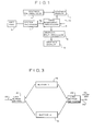
- Fig. 1 is a block diagram showing the basic components of the earlier system that was previously referred to.
- a graphics pre-processor 2 will convert the picture of the scene to be displayed into data stored at predetermined positions in the graphics memory 4.
- the image management processor 5, in conjunction with the instructions that it receives from software 6 via the system processor 7, will retrieve appropriate data from the graphics memory 4 and convert that data into a form which, after passing through the graphics post-processor 8, is fed to the graphics display 10, which may be a conventional TV picture tube, where a picture of the scene is formed and displayed.
- the graphics pre-processor 2 has done its job, loading the graphics memory 4 with appropriate 5data, it is disconnected from the system, which thereafter functions on its own.
- Fig. 2 is a more detailed block diagram of the image management processor 5.
- the input thereto from the software 6 and system processor 7 is at 12.
- Its connection to the Ographics memory 4 is shown at 14.
- each display block 20 in each of the buffers 16 and 18 corresponds to a particular pixel in each of the display lines of the graphics display 10.
- the length of time available between the beginning of the scan of one line on the graphics display 10 and the beginning of the scan of the display of the next line is very short, on the order of 64 microseconds.
- the two buffers 16 and 18 are used alternatively, with one being used to construct a line while the other is being used to actually display a line.
- the line buffer control 21 will connect one buffer, say the buffer 16, to the data input line 22, and will disconnect the buffer 18 therefrom, while at the same time the line buffer switching element 24-will connect the buffer 18 to the output line 26, while disconnecting the buffer 16 therefrom. That situation will continue while the graphics display 10 is scanning one line.
- the line buffer control 21 and the line buffer switching 24 will reverse their connections, so that during the next period of time the buffer 18 will be used for construction and the buffer 16 will be used for display. In this way sufficient time is provided to write data into all of the data blocks 20 alternatively in each of the buffers 16 and 18.
- One of the features of the earlier system is the storing of data for the scene in terms of object elements, that is to say, the separate individual portions of the objects in the scene as they are viewed.
- the objects are "fractured” into individual visible portions, those portions are individually stored in memory, and are retrieved from memory whenever the object of which they are a part is to be constructed.
- Figure 4 a scene comprising a cube 28, a parallelopiped 30 and a three-dimensional representation 32 of the letter B.
- the width of the parallelopiped 30 is the same as the width of the cube 28.
- the scene there shown may be "fractured” into seven object elements A-G, of >which object elements A and D are the same, so that only six object elements need be stored.
- Each of the individual objects in the scene is composed of separate surfaces.
- a cube or a parallelopiped has six surfaces, but in the particular picture here shown there are only three surfaces visible, so data with respect only to those three surfaces need be stored in memory.
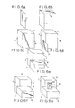
- Figure 5 illustrates the object elements in question, each set off separately, as they would be in memory.
- Figures 6a through 6g illustrate how the object 5elements of Fig. 5 would be used to create the overall scene, the object element being written in each individual figure being shaded. It will be understood that the scene is produced on the graphics display 10 as a series of display lines, and the data corresponding to the appropriate portion of an object element on a given display line will be inserted into the appropriate data blocks 20 along the length of whichever one of the buffers 16 or 18 is functioning as a construction buffer for that particular display line. This is indicated by the broken lines 34 on Fig. 4, which represent a particular display line on the graphics display 10. This explanation, for purposes of clarity, will ignore the line-by-line construction process.
- Fig. 5 represent the surfaces of the object in question which would be visible in the absence of all other objects.
- a cube 28 most remote from the viewer, is completely constructed, but when, in Fig.s 6d-6f, the parallelopiped 30 is constructed, it blocks out (erases) some of the representation of the cube 28.
- the letter B designated by the reference numeral 32, is inserted into the scene, portions of the cube and parallelopiped behind the letter are likewise erased.
- the color is defined by a 12 bit word, four bits defining the red component of the color, four bits defining the green component and four bits defining the blue component. It is these twelve bits which permit defining 4096 different colors.
- buffers 18 and 20 with 8 bits per pixel to construct ithose buffers one can choose from only 256 of those colors (see Fig. 7, a color map comprising a sequential list of 256 colors, each defined by a 12 bit value).
- the system can be operated in such an 8 bit mode.
- it is segmented into a series of 16 "color palettes". Each palette holds 16 colors, arbitrarily selected by the operator for the particular graphics task at hand.
- Each palette is numbered, and each of the colors in a given palette is numbered.
- the object description stored in memory 4 That description is in the form of an 8 bit word defining the address of the color, and when that address is interrogated a 12 bit word is found which defines the particular one of the 4096 colors that is involved.
- the earlier system provides that, in displaying object, the user has a choice of yet another mode - 2 bits per pixel.
- the mode defines the color resolution of the object. Using 8 bits per pixel one can use any or all of the 256 colors in defining an object. Using 4 bits per pixel lets one use one of 16 colors to define a pixel. Using 2 bits per pixel causes the pattern data to be read in groups of 2 bits and only gives one a choice of 4 colors to describe a pixel.
- each of the 16 color palettes are further subdivided into 4 "mini-palettes".
- Each mini-palette contains 4 colors. Since the list of 256 colors is still logically divided into the 16 color palettes, the correct way to reference a mini-palette is to first specify the color palette, then specify the mini-palette.
- the actual process of constructing the 8 bit word defining the color for a given pixel begins with the selection of the color resolution mode.
- Color resolution is specified within an object when its character and/or bit map strings are defined.
- the "palette select" argument addressing the palette you want to use must be filled in. If the 4 bit mode is selected one need only specify one of the 16 color palettes. The 4 bits representing the color palette number are placed in the high order 4 bits of the 6 bit word (the remaining 2 low order bits are not used in the 4 bit mode). If the 2 bit mode is selected, one must specify one of the 4 mini-palettes in addition to the color palette. The 2 bits representing the mini-palette number are placed in the lowest 2 bits of the 6 bit word.
- the first 4 bits are read from the object pattern data and deposited in the lower order 4 bits of the 8 bit word.
- the upper 4 bits of the 6 bit "palette select" word are then placed in the high order 4 bits of the 8 bit word.
- the 8 bit word now filled on the line buffer one pixel is completely specified as to choice of colormap selection.
- the system uses this colormap address (the 8 bit word) and displays the color associated with the 12 bit value it finds there.
- the first 2 bits are read from the object pattern data and deposited in the low order 2 bits of the 8 bit word.
- the entire 6 bit "palette select" word is then placed in the high order 6 bits of the 8 bit word.
- the 8 bit word With the 8 bit word filled, one pixel is ready to be colored in.
- the system looks at the colormap address (the 8 bit word) and displays the color associated with the 12 bit value it finds there. Note that in 2 bit mode, one colors twice as many pixels as 4 bit mode for each fetch of object pattern data.
- the pattern data supplies all 8 bits required to completely define the color choice of one pixel.
- the system uses this word, as before, to address the colormap and display the actual pixel color specified via the 12 bit value found there.
- Figures 9A, B and C illustrate how the earlier system supports the visual perception of a two-dimensional representation of a three-dimensional image.
- a close coupling is achieved between the luminance grading of 5the selected color palette and the binary coding of the object pattern as defined in the system memory.
- the visual perceived effect is that of a cone illuminated from the right, and the rectangle in Figure 9A represents a selected portion of the image.
- Fig. 9B is an expansion of that selected image portion showing certain arbitrary luminance shadings (dark to light), it being assumed for purposes of this example that the cone is of a single basic color.
- Fig. 9C is an illustration of the contents of the color map for the given example relative to the luminance values to be employed.
- Fig. 9B may be considered as a unit screen bit map, with the individual bits having color definitions corresponding to the shading in Fig. 9B and the particular colors in Fig. 9C. It should be understood that while this particular example has been described in terms of gradations in a single color, the cone being postulated as a monochromatic object the polychromatic aspects of which arise from its illumination and the way in which it is seen, multi-colored objects could have two-dimensional representations producing comparable three-dimensional effects by using appropriate different colors in the palette of Fig. 9C. If more than 16 individual colors are thought to be required to produce a given image, the object may be represented in memory as a plurality of object elements, each with its own 16 color palette, the object elements being appropriately spatially related.
- the system permits the display of character data as well as pictorial data, using known techniques.
- the system is also capable of providing windows -- an area on the graphics display screen 10 on which an independent image may be displayed. Each window is in essence a variable-size virtual screen.
- FIG. 8 The sequence of steps performed by the earlier system, under the control of appropriate software, producing a graphics display is schematically indicated in Figure 8, illustrating a linked list "tree" showing a procedure involved in connection with a given background (row) and foreground (slice) characteristic or attribute.
- a given line of a given image may involve a large number of row and slice attributes, the number being limited only by the time available to handle them.
- the software will produce real time display by traversing the tree structure, filling in )appropriate nodes with information about the objects that are to be displayed, their positions relative to the screen and each other, and the pattern data to be used for the current representation of the image.
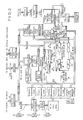
- FIG. 10 is a block diagram of a system in accordance 5with an embodiment of this invention.
- a first memory component A hereinafter termed “pattern memory” receives and stores data, usually in the form of a bit map, defining the appearance of those object elements which, it is expected, will be displayed over a period of time, although in most instances not all of those elements will be displayed in any given moment.
- An object element may be considered as an independent pictorial entity, which may in turn .be made up of a plurality of sub-elements.
- the system of this embodiment enables that object element, or ''clip"-selected sub-elements thereof, to be freely positioned over the display space and to be unrestrictively overlaid over previous patterns placed in that display space.
- Such overlaying involves user-definable visible priority in terms of whether a given object element will appear in front of or behind another object element, thus enabling three-dimensional animation effects to be produced.
- Each individual object element is identified in some appropriate fashion, as by its location in that portion of the memory constituting the first memory component A.
- the pattern memory A forming a part of the display system may be augmented by memory structure external of the system proper, e.g., an attached disc storage instrumentality.
- the second memory component B may contain program instructions and will also contain data, preferably in the form of linked lists of the type generally described above in conjunction with the earlier system, identifying various components of a desired display and containing display instructions relative thereto, such as defining where on the screen the display of the object element is to be located, what its size is to be, what its color is to be and what, if any, manipulations (e.g. pan, zoom, warp, rotate) are to be performed on the relevant data stored in pattern memory A before that data is actually displayed.
- This data stored in the system memory B relates to all portions of the display which are to be formed throughout the period of operation of the system, and is not limited to the data needed for a display at any particular moment.
- a data processing unit functions before a display run is commenced to deposit the appropriate data in the pattern memory A and the system memory B, obtaining that data from some external source, and the system processor D may also be used to update the data in pattern memory A and/or system memory B, in accordance with instructions and that either internally stored or received from an external host computer, while the system is operating to produce displays. It further loads color information into a color map memory G.
- the system processor D performs an additional function. As display time passes it reads from the linked lists of system memory B that identification and display instruction data relevant to creating a display at a particular moment, and it deposits that data into the third memory component C. That which is deposited will hereafter be termed "the compiled list", which may well be in the form of a sequential list, and hence the memory component C will hereinafter be termed the compiled list memory C.
- the compiled list represents the object element identification and relevant display instructions of a particular instantaneous display, this being usually only a small proportion of the corresponding data stored in the system memories A and B.
- FI and FII which, as here specifically disclosed, correspond to the alternately acting buffers 16 and 18 (Fig. 3) of the earlier system.
- the two display/construction buffers FI and FII are here disclosed as constructing lines of the display, one such buffer being constructed by having data put thereinto by the graphics painter E while the other such buffer is acting to produce a line display, the functions of the two buffers FI and FII alternating in time.
- the graphics painter E may access the system memory B and the pattern memory A on a line-by-line basis.
- the output from the construction/display buf-fers F goes to the color map G, into which appropriate data had previously been stored by the system processor D, and from there the display data goes to digital to analog converter H, from which a composite video signal I system goes to the display instrumentality, in known manner.
- system processor D in response to information received from outside the system or ) from the program in system memory B, modify the linked lists in the system memory B in real time without affecting the capability of the system to produce real time displays.
- two compiled lists C-I and C-II are provided, each of which may contain the appropriate identification and 5display instruction data for a given frame.
- the data in the compiled list C compresses the identification and the display instructions relating to the visible objects in the scene to be displayed at a given moment.
- the amount of data required for the compiled list C cannot, as a practical matter, be generated in line time, yet each of the construction/display buffers F are constructed in line time.
- the compiled list C relates to an entire frame, that list can be generated in frame time, and since typically there are 525 lines to a frame in a conventional TV display, that gives 525 times more time for compiled list construction than for line buffer construction when the display is to be changed thirty times a second (the time to display a given frame), thus enabling the system to handle significantly more data than previous systems and thus produce considerably more sophisticated displays. If the display need not be changed so frequently, there is a corresponding increase in the time available to generate a given compiled list.
- system processor D can handle much more data in real time than was possible in the earlier system.
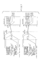
- Fig. 11 represents a typical linked list arrangement of object element identification and display data stored in the system memory B.
- Data is there stored in a hierarchy of attributes, with some or all of those attributes being further arranged in the form of linked lists ordered in terms of visible priority.
- the highest or most general attribute is the frame attribute 2, next in order are the window attributes 4, and, for each window attribute 4, the various object attributes 6 associated therewith.
- a series of symbol attributes 8 may be stored, each of which may also include a list of sub-identifications (called “children"), e.g., "dog” may be the main symbol and "dog walking", “dog sitting”, “dog jumping”, etc., may be “children".
- the data stored for the frame attribute 2 which represents an overall scene to be displayed at a given moment, comprises its desired x and y origin points on the display screen, a pointer to the window list or lists that are to be used in that frame, and an identification of the highest priority window in the window list which is to be used.
- a “window”, as here used, is a defined viewpoint, or rectangle through which selected object elements are to be viewed, the window itself definingthe bounds of the viewing area and hence determining what portion of the selected object element is to be displayed.
- Each window attribute 4 contains data defining its desired location on the display, its size, linking pointers, preferably to both the preceding as well as the succeeding window in the linked list, a pointer to the object list or lists to be included in the window, a pointer to the highest priority object in that list which is to be displayed, and.an identification of the window to match with the appropriate symbol attribute 8.
- Each object attribute 6 includes a pointer to pattern memory A, identifying the pictorial data in that pattern memory A which relates to the particular object, the desired location of the object, its size, a definition of the number of bits per display pixel, identification of the color palette to be used, and identification of the symbol attribute 8 that is to correspond to that object, as well as data identifying the object itself.
- Each symbol attribute 8 may contain data defining an identifying name, so that it can be manually or automatically selected, together with data concerning its size, its location in the pattern memory A and, if desired, data concerning various manipulations which might be performed to controllably modify or distort the display image as well as links, preferably in both directions, to the allied "children" data.
- the object attribute 6 data restricting the portion of the relevant display object which is -to be displayed.
- This data can be in the form of words identifying the location of the top, left-hand side, bottom and right-hand side of the area to be clipped and, if a particular object within a composite object element is fractured by the clip, additional words defining the overall clip conditions with respect to that object.
- the clip in effect constitutes a restricted area of observation within that portion of the window of which the clip may be a part. Hence only that portion of the object element will be displayed which is both within the window 'attribute 4 definition and the clip instructions definition.
- the relevant clip data is added to the object attribute data shown in Fig. 11.
- Fig. 13 is a representation of a particular body of data relating to a particular display object as it may be produced and temporarily stored in a 5 compiled list C.
- the first line 10 of that data is a pointer. to pattern memory A identifying the particular line of that pattern memory to which the painter E should go. That line typically comprises four bytes of eight bits each. It usually takes more than one line of pattern memory to create one display line of the object, and therefore the compiled list for a given line of an object may require sequential reference to a plurality of pattern memory lines.
- the data in line 10 initially points to the line in memory where the picture is to start.
- the "bottom line” and “top line” units 13 and 15 in line 12 indicate the position that the object should assume on the display screen. Each requires nine bits, but the memory is only sixteen bits wide. Therefore the "0 top” and “0 bottom” units in lines 4 and 17 respectively represent the ninth needed bit in the top and bottom line items 13 and 15 respectively.
- the "last" item 16 is a flag which appears only when the data block is used for the last time in a sequence.
- the "clip” item 20 is a flag indicating whether or not a clip is involved.
- the "pattern page” item 22 is used in conjunction with pattern pointer 10 in order to direct the painter E to the right spot in memory.
- the "full pattern width” item 24 in line 14 and the “relative width” item 40 in line 38 represent respectively an indication of the number of pixels which make up the entire object line and the number of pixels needed to make up the object line taking into consideration the proportion of the entire object to be displayed.
- the "X position” item 28 in line 17 identifies the desired horizontal position where the display of the object element should start.
- the "left delta” and “right delta” units 30 and 32 are used when, because of clip or window constraints, not all of a given line in memory is to be used in painting the line of the picture.
- the second "pattern pointer" unit in line 36 identifies the first line of the relevant data in the pattern memory A.
- the first pattern pointer 10 and the second pattern pointer 36 are initially the same but, as the compiled list is followed and the painter E is directed to different lines in memory for a given object element, the first pattern pointer unit 10 points to those lines sequentially, being changed by the value of full pattern width 24 each time the data structure is run through and the object or portion thereof is to be )displayed.
- the second "pattern pointer" unit 36 which remains constant, is used to return the first "pattern pointer" unit 10 to its initial value after the last sequence has been carried out.
- the data unit 41 identifies the number of bits per pixel to be employed in 5 making the display, and the "palette” unit 42 identifies the particular color that is to be used in displaying that particular portion of the object element.
- All of the compiled list data such as is exemplified by Fig. 13 may be deposited in an area or unit of memory dedicated to that purpose, but this is not essential.
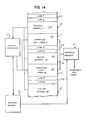
- the compiled list data may, from a physical or geographical viewpoint, be integrated with the linked list data of the system memory B. This is schematically indicated in Fig. 14, where a given unit 44 from system memory B, such as a particular object attribute 6, is immediately followed geographically by that portion 46 of the compiled list C which has been created by the system processor D in accordance with that particular object attribute 6.
- Next in line, at area 48, may be the next object attribute 6A in a 'given linked list of object attributes (see Fig.
- Fig. 12 is a block diagram of the same general character as Fig. 11 but showing a typical arrangement of linked lists and the data involved in those linked lists where animation instructions are integrated with the identification and other display instructions of the linked list system of Fig. 11.
- Fig. 12 there is a first linked y list 2A of frame attributes linked in terms of time because of the animation, each of the attributes thereof pointing to one or more linked lists 4A of window attributes.
- the system of Fig. 12 contains, for each window attribute 4A, one or more lists 54 of animation attributes, linked in border of visual priority, each of which in turn points to one or more linked lists 56 of view attributes and one or more linked lists 58 of trail attributes.
- the view attributes 56 correspond generally to the object attributes 6 of the system of Fig.
- the view attributes of a given linked list 56 represent views of the same object different from one another in a manner such as to produce an animation effect when sequentially displayed.
- the view attributes in a given linked list 56 are ordered in time (visual priority is controlled by the linking in the animation attributes list 54).
- the trail attributes of linked list 58 also ordered in time, control the sequence of different physical locations where the individual view attribute objects are displayed, thus causing the objects to traverse a specified route on the display screen.
- the ianimation attributes give instructions as to how the view attribute linked list 56 and trail attribute linked list 58 are to be traversed (forward, backward or in circulatory fashion, sequentially or by skipping individual views).
- a display can be produced only so long as the line buffers F have access, via the graphics painter E, to the pattern memory A, since it is only with such access that the display lines can be constructed in the buffers F.
- the pattern memory A has to be available to other sources, formation of a display must cease. This greatly restricts the capability of the system to function while at the same time permitting updating of the pattern memory A. Yet it is often necessary to revise or update the contents of pattern memory A (and also system memory B) to an extent such as to be impossible to accomplish within real time constraints. When that occurs the display screen goes blank. That may occur for only a fraction of a second or for many seconds, depending upon the extent to which the contents of pattern memory A are changed, but such blanking of the display is undesirable in any event.
- Fig. 15 avoids this disadvantage by interposing between the construction/display line buffers F and the color map G a frame buffer K.
- the lines constructed by the line buffers F are in turn constructed in the frame buffer K, where they remain until modified, and the line-by-line data is fed from frame buffer K to the composite video signal I in any appropriate known manner.
- the frame buffer K ensures that a scene is still displayed. That scene is static, because no changes are being made in any of the lines stored in the frame buffer K, but a static scene is preferable to no scene at all.
- a second limitation in the functioning of the systems of previous embodiments is that construction is accomplished on a line-by-line basis. As a result the total number of objects that can be supported by the system is limited by the "highest band width" line. In addition, the entire >object list in system memory B is traversed for each line to be constructed, although a good portion of that list will be irrelevant to the particular line under construction. This results in a significant waste of operating time. Both of these factors significantly adversely affect the amount of O data that can be handled by the system in real time and tend to limit the degree of detail with which particular objects can be displayed.
- Fig. 16 substitutes frame buffers F' for the line buffers F of 5the embodiment of Fig. 15.
- each of the frame buffers F' will accommodate half of the total frame, the buffer F'-I being adapted to contain the odd lines of the frame and the buffer F'-II being adapted to contain the even lines of the frame (it is conventional, in making up a display on a screen, to first sequentially display the odd lines of the frame and then to sequentially display the even lines thereof).
- the two buffers F'-I and F'-II 5 contain data for a complete display, if access to the pattern memory A by the graphics painter E is interrupted, as described above, a static display can be produced by the buffers F'-I and F'-II. Hence there need be no blanking of the display screen even when extensive updating of pattern memory A from the external source J takes place.
- Fig. 16 show an optional modification of the system there disclosed. Instead of having the frame buffers F'-I and F'-II feed directly to the color map G, they can be caused to feed to an extra full frame buffer K', which in turn feeds the color map G. This extra full frame buffer K' is not needed to prevent blanking of the display when the pattern memory A is not available -the frame buffers F'-I and F'-II accomplish that, as has been described.
- the function of the extra frame buffer K' is to reduce the time that the display must be static by making the buffers F'-I and F'-II available to be used for construction while the buffer K' ensures continuity of static display, and also enables the buffers F' to be accessed by a third source, such as a TV camera, while continuity of the static display is ensured.
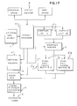
- Fig. 17 is similar to the embodiment of Fig. 16 except that the construction/display buffers F" are each full frame buffers having the capacity to store data for both the odd lines and the even lines of the 5 display.
- That chart discloses four time slots, each typically representing the time required to display either the odd or even lines of a display, two such time slots of 1/60th of a second each making up the conventional frame time of 1/30th of a second.
- a first frame is displayed in time slots 1 and 2
- a second frame is displayed in time slots 3 and 4, and so on.
- the painter E constructs a frame in buffer F"-I, an earlier frame having been previously constructed in buffer F"-II.
- the even lines of the display are produced from the appropriate data-in buffer F"-II.
- the odd lines of the display are produced from buffer F"-II, but since the next frame has already been constructed in buffer F"-I, nothing more need be done with respect to that buffer. Hence the time of that second time slot is now available for the external data source J to update the data in pattern memory A via the system processor D.
- the graphics painter E is prevented from having access to the pattern memory A during the second time slot, but it does not need that access.
- the graphics painter E is again given access to the pattern memory A and constructs the next frame in frame buffer F" - II, and in the same time slot the even lines of the display are produced from the appropriate data in buffer F"-I.
- Fig. 17 could be employed, in conjunction with a "live" data source such as a TV camera, to construct one frame buffer F"-I from data provided by the graphics painter E and construct the other frame buffer F"-II from the data provided by the "live” data source.
- a "live” data source such as a TV camera
- Fig. 17 could, if desired, be provided with the extra full frame buffer K' of Fig. 16, to produce the results previously set forth above.
Landscapes
- Engineering & Computer Science (AREA)
- Physics & Mathematics (AREA)
- Computer Hardware Design (AREA)
- General Physics & Mathematics (AREA)
- Theoretical Computer Science (AREA)
- Processing Or Creating Images (AREA)
- Digital Computer Display Output (AREA)
Applications Claiming Priority (4)
| Application Number | Priority Date | Filing Date | Title |
|---|---|---|---|
| US705367 | 1985-02-25 | ||
| US06/705,367 US4760390A (en) | 1985-02-25 | 1985-02-25 | Graphics display system and method with enhanced instruction data and processing |
| US74083285A | 1985-06-03 | 1985-06-03 | |
| US740832 | 1985-06-03 |
Publications (2)
| Publication Number | Publication Date |
|---|---|
| EP0194092A2 true EP0194092A2 (fr) | 1986-09-10 |
| EP0194092A3 EP0194092A3 (fr) | 1990-02-07 |
Family
ID=27107495
Family Applications (1)
| Application Number | Title | Priority Date | Filing Date |
|---|---|---|---|
| EP86301351A Withdrawn EP0194092A3 (fr) | 1985-02-25 | 1986-02-25 | Dispositif et méthode de visualisation |
Country Status (2)
| Country | Link |
|---|---|
| EP (1) | EP0194092A3 (fr) |
| CA (1) | CA1257719A (fr) |
Cited By (9)
| Publication number | Priority date | Publication date | Assignee | Title |
|---|---|---|---|---|
| EP0312720A3 (fr) * | 1987-10-20 | 1990-06-13 | Tektronix Inc. | Système de dessein graphique à double mémoire-tampon |
| EP0264099A3 (en) * | 1986-10-15 | 1990-11-07 | Atari Games Corporation | Lookahead pipeline for processing object records in a video system |
| EP0268070A3 (en) * | 1986-10-15 | 1990-11-07 | Atari Games Corporation | Object processing for video system using slips and linked list |
| EP0314440A3 (fr) * | 1987-10-26 | 1991-03-13 | Tektronix, Inc. | Système d'affichage graphique avec une mémoire d'éléments d'image secondaire |
| EP0323636A3 (fr) * | 1987-12-30 | 1991-10-23 | Namco, Ltd. | Système d'affichage d'objets |
| US5202672A (en) * | 1987-12-30 | 1993-04-13 | Namco Ltd. | Object display system |
| WO1997006523A1 (fr) * | 1995-08-08 | 1997-02-20 | Cirrus Logic, Inc. | Systemes et memoires unifies de memoire tampon image/systeme et leurs methodes d'utilisation |
| US5706033A (en) * | 1993-11-09 | 1998-01-06 | Kabushiki Kaisha Toshiba | Display data readout circuit |
| WO2001001386A1 (fr) * | 1999-06-30 | 2001-01-04 | Aurora Systems | Affichage a cristaux liquides multistandard avec ajustement automatique du signal de reglage |
Families Citing this family (1)
| Publication number | Priority date | Publication date | Assignee | Title |
|---|---|---|---|---|
| JP2001103392A (ja) | 1999-09-29 | 2001-04-13 | Nec Ic Microcomput Syst Ltd | 画像枠生成回路及びそれを用いたデジタルテレビシステム |
Family Cites Families (3)
| Publication number | Priority date | Publication date | Assignee | Title |
|---|---|---|---|---|
| US3996585A (en) * | 1974-06-11 | 1976-12-07 | International Business Machines Corporation | Video generator circuit for a dynamic digital television display |
| US4317114A (en) * | 1980-05-12 | 1982-02-23 | Cromemco Inc. | Composite display device for combining image data and method |
| GB2137856B (en) * | 1983-04-06 | 1987-07-08 | Quantel Ltd | Image processing system |
-
1986
- 1986-02-25 EP EP86301351A patent/EP0194092A3/fr not_active Withdrawn
- 1986-02-25 CA CA000502655A patent/CA1257719A/fr not_active Expired
Cited By (9)
| Publication number | Priority date | Publication date | Assignee | Title |
|---|---|---|---|---|
| EP0264099A3 (en) * | 1986-10-15 | 1990-11-07 | Atari Games Corporation | Lookahead pipeline for processing object records in a video system |
| EP0268070A3 (en) * | 1986-10-15 | 1990-11-07 | Atari Games Corporation | Object processing for video system using slips and linked list |
| EP0312720A3 (fr) * | 1987-10-20 | 1990-06-13 | Tektronix Inc. | Système de dessein graphique à double mémoire-tampon |
| EP0314440A3 (fr) * | 1987-10-26 | 1991-03-13 | Tektronix, Inc. | Système d'affichage graphique avec une mémoire d'éléments d'image secondaire |
| EP0323636A3 (fr) * | 1987-12-30 | 1991-10-23 | Namco, Ltd. | Système d'affichage d'objets |
| US5202672A (en) * | 1987-12-30 | 1993-04-13 | Namco Ltd. | Object display system |
| US5706033A (en) * | 1993-11-09 | 1998-01-06 | Kabushiki Kaisha Toshiba | Display data readout circuit |
| WO1997006523A1 (fr) * | 1995-08-08 | 1997-02-20 | Cirrus Logic, Inc. | Systemes et memoires unifies de memoire tampon image/systeme et leurs methodes d'utilisation |
| WO2001001386A1 (fr) * | 1999-06-30 | 2001-01-04 | Aurora Systems | Affichage a cristaux liquides multistandard avec ajustement automatique du signal de reglage |
Also Published As
| Publication number | Publication date |
|---|---|
| CA1257719A (fr) | 1989-07-18 |
| EP0194092A3 (fr) | 1990-02-07 |
Similar Documents
| Publication | Publication Date | Title |
|---|---|---|
| US4760390A (en) | Graphics display system and method with enhanced instruction data and processing | |
| US4700181A (en) | Graphics display system | |
| US5295235A (en) | Polygon engine for updating computer graphic display employing compressed bit map data | |
| US5546518A (en) | System and method for composing a display frame of multiple layered graphic sprites | |
| US4967392A (en) | Drawing processor for computer graphic system using a plurality of parallel processors which each handle a group of display screen scanlines | |
| CN101065784B (zh) | 计算机图形处理 | |
| US5889499A (en) | System and method for the mixing of graphics and video signals | |
| DE69427574T2 (de) | NTSC-Anzeige der Animation bewegter Bilder | |
| US4812834A (en) | Graphics display system with arbitrary overlapping viewports | |
| KR100411534B1 (ko) | 영상데이터생성방법,생성장치및생성회로,및게임재생장치 | |
| US4225861A (en) | Method and means for texture display in raster scanned color graphic | |
| US4570233A (en) | Modular digital image generator | |
| US4951229A (en) | Apparatus and method for managing multiple images in a graphic display system | |
| KR950012931B1 (ko) | 도형처리장치 및 도형처리방법 | |
| US4868557A (en) | Video display apparatus | |
| DE3851680T2 (de) | Einrichtung zur Änderung der Bildelementdaten, die in einem Direktzugriffsspeicher gespeichert sind. | |
| US20060125848A1 (en) | Systems and methods for rendering graphical data | |
| CA1257719A (fr) | Systeme d'affichage graphique | |
| EP0043703B1 (fr) | Dispositif de commande d'un système d'affichage à balayage à trame | |
| EP0538056B1 (fr) | Système de traitement d'image | |
| US4864517A (en) | Graphics display system using frame buffers | |
| EP0887768B1 (fr) | Processeur graphique et méthode de traitement graphique | |
| WO1992003815A1 (fr) | Production d'images video | |
| JP3721623B2 (ja) | 描画色変更方法、及び動画再生装置 | |
| JP3750171B2 (ja) | 描画色変更方法、及び画像作成装置 |
Legal Events
| Date | Code | Title | Description |
|---|---|---|---|
| PUAI | Public reference made under article 153(3) epc to a published international application that has entered the european phase |
Free format text: ORIGINAL CODE: 0009012 |
|
| AK | Designated contracting states |
Kind code of ref document: A2 Designated state(s): DE FR GB NL SE |
|
| PUAL | Search report despatched |
Free format text: ORIGINAL CODE: 0009013 |
|
| AK | Designated contracting states |
Kind code of ref document: A3 Designated state(s): DE FR GB NL SE |
|
| 17P | Request for examination filed |
Effective date: 19900803 |
|
| STAA | Information on the status of an ep patent application or granted ep patent |
Free format text: STATUS: THE APPLICATION IS DEEMED TO BE WITHDRAWN |
|
| 18D | Application deemed to be withdrawn |
Effective date: 19910819 |
|
| RIN1 | Information on inventor provided before grant (corrected) |
Inventor name: MAINE, STEPHEN Inventor name: MAMMEN, ABRAHAM Inventor name: HARROWER, DUNCAN |