EP0194208A2 - Patronenzuführvorrichtung und Magazin für ein treibladungsgetriebenes Gerät - Google Patents
Patronenzuführvorrichtung und Magazin für ein treibladungsgetriebenes Gerät Download PDFInfo
- Publication number
- EP0194208A2 EP0194208A2 EP86400488A EP86400488A EP0194208A2 EP 0194208 A2 EP0194208 A2 EP 0194208A2 EP 86400488 A EP86400488 A EP 86400488A EP 86400488 A EP86400488 A EP 86400488A EP 0194208 A2 EP0194208 A2 EP 0194208A2
- Authority
- EP
- European Patent Office
- Prior art keywords
- cartridges
- axis
- annular space
- barrel
- line
- Prior art date
- Legal status (The legal status is an assumption and is not a legal conclusion. Google has not performed a legal analysis and makes no representation as to the accuracy of the status listed.)
- Granted
Links
- 239000002360 explosive Substances 0.000 title claims abstract description 5
- 238000010304 firing Methods 0.000 claims description 14
- 238000006073 displacement reaction Methods 0.000 claims description 6
- 229920003023 plastic Polymers 0.000 claims description 5
- 239000000463 material Substances 0.000 claims description 3
- 238000012423 maintenance Methods 0.000 claims 1
- 238000009527 percussion Methods 0.000 description 6
- 238000007789 sealing Methods 0.000 description 3
- 238000003307 slaughter Methods 0.000 description 3
- 241000283690 Bos taurus Species 0.000 description 1
- 239000000853 adhesive Substances 0.000 description 1
- 230000001070 adhesive effect Effects 0.000 description 1
- 238000010276 construction Methods 0.000 description 1
- 230000005484 gravity Effects 0.000 description 1
- 230000002452 interceptive effect Effects 0.000 description 1
- 244000144972 livestock Species 0.000 description 1
- 230000004048 modification Effects 0.000 description 1
- 238000012986 modification Methods 0.000 description 1
- 239000011435 rock Substances 0.000 description 1
Images

Classifications
-
- A—HUMAN NECESSITIES
- A22—BUTCHERING; MEAT TREATMENT; PROCESSING POULTRY OR FISH
- A22B—SLAUGHTERING
- A22B3/00—Slaughtering or stunning
- A22B3/02—Slaughtering or stunning by means of bolts, e.g. slaughtering pistols, cartridges
-
- B—PERFORMING OPERATIONS; TRANSPORTING
- B25—HAND TOOLS; PORTABLE POWER-DRIVEN TOOLS; MANIPULATORS
- B25C—HAND-HELD NAILING OR STAPLING TOOLS; MANUALLY OPERATED PORTABLE STAPLING TOOLS
- B25C1/00—Hand-held nailing tools; Nail feeding devices
- B25C1/08—Hand-held nailing tools; Nail feeding devices operated by combustion pressure
- B25C1/10—Hand-held nailing tools; Nail feeding devices operated by combustion pressure generated by detonation of a cartridge
- B25C1/18—Details and accessories, e.g. splinter guards, spall minimisers
- B25C1/182—Feeding devices
- B25C1/186—Feeding devices for cartridges or pellets
-
- F—MECHANICAL ENGINEERING; LIGHTING; HEATING; WEAPONS; BLASTING
- F41—WEAPONS
- F41A—FUNCTIONAL FEATURES OR DETAILS COMMON TO BOTH SMALLARMS AND ORDNANCE, e.g. CANNONS; MOUNTINGS FOR SMALLARMS OR ORDNANCE
- F41A9/00—Feeding or loading of ammunition; Magazines; Guiding means for the extracting of cartridges
- F41A9/38—Loading arrangements, i.e. for bringing the ammunition into the firing position
-
- F—MECHANICAL ENGINEERING; LIGHTING; HEATING; WEAPONS; BLASTING
- F41—WEAPONS
- F41A—FUNCTIONAL FEATURES OR DETAILS COMMON TO BOTH SMALLARMS AND ORDNANCE, e.g. CANNONS; MOUNTINGS FOR SMALLARMS OR ORDNANCE
- F41A9/00—Feeding or loading of ammunition; Magazines; Guiding means for the extracting of cartridges
- F41A9/61—Magazines
- F41A9/64—Magazines for unbelted ammunition
- F41A9/73—Drum magazines
Definitions
- the present invention relates to a new device for supplying cartridges to an apparatus operating with the aid of an explosive charge, such as for example a sealing gun or a livestock slaughtering apparatus.
- the invention also relates to a charger intended to be used in this device.
- the invention relates to apparatus of the type wherein, after the barrel has been cleared i t of the yoke by an unlocking movement, the latter is pivotable relative to the barrel about an axis parallel to the axis of the latter, so that by this pivoting movement, it is possible to bring a supply channel containing a line of cartridges in front of the cartridge holder disposed at the rear of the barrel, then only by a reverse movement, the cylinder head can be locked to ignite the cartridge which was thus engaged in the cartridge holder.
- the present invention aims to achieve an apparatus of this type which is simple in construction, compact and easy to use.
- the subject of the present invention is a device for supplying cartridges to a device operating with an explosive charge of the type in which, after unlocking the breech, the latter can be pivoted relative to the barrel around an axis parallel to the latter, so as to bring in the axis of the cartridge chamber, a channel containing a line of cartridges, characterized in that the cartridges are arranged in parallel lines in an annular space located on the periphery of the breech, a line of cartridges being in a position such that after unlocking the breech, and pivoting of the latter relative to the barrel, said line is located in the axis of the cartridge holder, an appropriate device making it possible to make successively come the different lines of cartridges in the direction of the feed channel of the barrel cartridge chamber.
- the cartridges are arranged in a loading strip, for example of plastic material which comprises a series of tubes capable of each receiving a line of cartridges, said tubes being connected to each other by flexibly so that said strip can be wound in the annular space around the cylinder head.
- a loading strip for example of plastic material which comprises a series of tubes capable of each receiving a line of cartridges, said tubes being connected to each other by flexibly so that said strip can be wound in the annular space around the cylinder head.
- the cartridges are arranged in a magazine comprising a succession of tubes each receiving a line of cartridges, which are connected to each other to form a configuration of cylindrical shape.
- This charger strip and this charger are also objects of the invention.
- the annular space which receives the rows of cartridges comprises an external wall whose diameter is substantially the same as that of the front part of the cylinder head, and which is capable of pivoting relative to to the latter by an angle which corresponds to the angular distance of two lines of cartridges.
- the internal wall of the annular space which receives the lines of cartridges is capable of pivoting around the cylinder head of the device, a holding member such as a ball system pushed back by a spring elastically maintaining this internal wall as well as the cartridge lines which are angularly integral therewith, in the positions where a line of cartridges is in the axis of the supply channel which, after unlocking the cylinder head, makes it possible to bring the cartridges in the axis of the holder cartridge.
- a ratchet device is such that when one drives in alternating rotations, the external wall of the annular space containing the cartridge lines, the internal wall, and the cartridge lines which are integral therewith, move in a line to the other of cartridges for a rotation in one direction, and undergo no displacement in the other direction of the displacement of the external wall of the annular space.
- This rotational movement of the outer wall of the annular space which contains the cartridge lines can moreover be used to rotate in one direction and in the other, the breech relative to the barrel after unlocking of the latter.
- the present invention can be used both on apparatuses used for example for the slaughter of cattle, which do not include any butt, and which are held by the external cylindrical part of the breech, as for the apparatuses with buttstock which are commonly used for fix in various materials, studs or dowels.
- the trigger or the firing lever in the vicinity of the striker, so as to prevent this device from interfering with the strip-magazine or the magazine according to the invention.
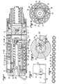
- the barrel In the unlocked position, the barrel can, in the known manner pivot relative to the breech about an axis parallel to the axis of the barrel, but which is offset relative to the latter, so as to bring the axis of the supply channel 5 in the axis of the cartridge holder 6.
- the cartridges are arranged in an annular space 7 arranged at the external periphery of the cylinder head 4.
- This space 7 is delimited by an external wall 8, which is provided with a bottom 9 held by a plug 10, screwed onto the cylinder head.
- the external wall 8 is mounted in such a way that it can pivot freely relative to the cylinder head 4.
- the outer wall 8 has a notch 11, inside which engages a lug 1 2, secured to the cylinder head with a screw 13.
- the dimensions of the notch 11 and lug 12 are such that the angular displacement of the external wall 8 corresponds to the angular distance separating two lines of cartridges 14 in the annular space 7.
- the space 7 also includes an internal wall 15 which is capable of pivoting freely around the cylindrical external part of the cylinder head 4.
- the cylinder head comprises a ball device 16 pushed back by a spring which is capable of engaging in a series of orifices 17 arranged on the periphery of the wall 15 at angular distances corresponding to the angular distances which separate the different lines of cartridges 14 .
- the end part situated to the left of the wall 15 has the form of a rack 18, as shown in broken lines in FIG. 1.
- the bottom 9 of the external wall 8 comprises a spring pawl 19 which cooperates with the rack 18, so that in one direction of rotation of the wall 8, the inner wall 15 is driven in the same rotation, while in the other direction, this inner wall 15 is immobilized by the spring ball 16.
- this strip consists of a series of tubes 19 which each contain a line of cartridges 1 4, and which are joined together by zones 20.
- the tubes 19 and the parts 20 are preferably made of plastic, so as to easily obtain flexibility of the loading strip which can take the circular shape which has been shown in FIG. 5.
- the tubes 19 are rigidly joined together by the parts 20 so as to have a circular configuration.
- the tubes 19 are permanently closed at one end to facilitate loading with cartridges and a removable closure, for example constituted by an adhesive sheet, is placed at the other end of the tubes and is removed when the charger is placed on the device according to the invention.
- a removable closure for example constituted by an adhesive sheet
- the external wall 8 and the magazine are preferably made of transparent plastic so as to be able to see the cartridges contained in the magazine.
- pins 21 are arranged on the periphery of the internal wall 15 which slide between two contiguous tubes 19 thus ensuring the positioning of the cartridge lines with respect to the wall 15.
- the firing device which in this embodiment, consists of a lever 22, pivoting about an axis 23 and which is provided with a rod 24 capable of engaging in front the head 25 of the percussion hammer 26 which is constantly pushed back by the spring 27.
- a spring shown in FIG. 3 constantly pushes the firing lever in a position such that the rod 24 comes to be placed in front of the head 25 of the hammer firing and prevents percussion.
- FIG. 6 a sectional view of a butted sealing gun comprising the supply device according to the invention.
- the device of FIG. 6 comprises a cylinder head produced in two parts 4 2 and 412 which are capable of sliding axially with respect to each other, so as to allow security such that, for the firing can be carried out, it is necessary that one applies to the butt 29, integral with the rear part 4a of the cylinder head, sufficient force to compress the spring 33 which constantly pushes the part 4b of the cylinder head to the right.
- the supply channel 5 comprises a sliding part 34 which ensures permanent guiding of the cartridges and this despite the variation in length of this channel.
- this device is the same as for the device of FIG. 1, the loading handling being carried out with one hand on the barrel and one hand on the external wall 8 which surrounds the breech.
- the device for holding the cartridge lines in the axis of the supply channel can be produced in a different way than that which has been described, as well as the snap device which allows you to rotate the cartridges by a corresponding angle to bring a new line of cartridges in line with the feed channel.
Landscapes
- Engineering & Computer Science (AREA)
- General Engineering & Computer Science (AREA)
- Life Sciences & Earth Sciences (AREA)
- Food Science & Technology (AREA)
- Chemical & Material Sciences (AREA)
- Combustion & Propulsion (AREA)
- Mechanical Engineering (AREA)
- Portable Nailing Machines And Staplers (AREA)
Applications Claiming Priority (2)
| Application Number | Priority Date | Filing Date | Title |
|---|---|---|---|
| FR8503417A FR2578639B1 (fr) | 1985-03-08 | 1985-03-08 | Dispositif d'alimentation en cartouches d'un appareil fonctionnant a l'aide d'une charge explosive et chargeur destine a alimenter ledit appareil |
| FR8503417 | 1985-03-08 |
Publications (3)
| Publication Number | Publication Date |
|---|---|
| EP0194208A2 true EP0194208A2 (de) | 1986-09-10 |
| EP0194208A3 EP0194208A3 (en) | 1986-12-30 |
| EP0194208B1 EP0194208B1 (de) | 1989-12-20 |
Family
ID=9316998
Family Applications (1)
| Application Number | Title | Priority Date | Filing Date |
|---|---|---|---|
| EP86400488A Expired EP0194208B1 (de) | 1985-03-08 | 1986-03-07 | Patronenzuführvorrichtung und Magazin für ein treibladungsgetriebenes Gerät |
Country Status (6)
| Country | Link |
|---|---|
| US (1) | US4686786A (de) |
| EP (1) | EP0194208B1 (de) |
| AU (1) | AU585321B2 (de) |
| CA (1) | CA1268370A (de) |
| DE (1) | DE3667725D1 (de) |
| FR (1) | FR2578639B1 (de) |
Cited By (1)
| Publication number | Priority date | Publication date | Assignee | Title |
|---|---|---|---|---|
| US8568550B2 (en) | 2010-10-22 | 2013-10-29 | Schott Ag | Method for the production of a protection device |
Families Citing this family (8)
| Publication number | Priority date | Publication date | Assignee | Title |
|---|---|---|---|---|
| US4926861A (en) * | 1987-10-08 | 1990-05-22 | Harrier Inc. | Method for in vivo treatment of tumorous tissues on body surfaces |
| DE69027305T2 (de) * | 1989-01-25 | 1996-10-02 | Ramset Fasteners Aust Pty Ltd | Motorgetriebenes befestigungswerkzeug |
| US5785229A (en) * | 1993-06-18 | 1998-07-28 | Framatome Connectors Usa, Inc. | Powder actuated connecting tool firing mechanism adapter |
| US6318228B1 (en) * | 1997-04-24 | 2001-11-20 | Ramtech 2000, L.L.C. | Forcible entry device |
| US6631668B1 (en) | 2000-11-10 | 2003-10-14 | David Wilson | Recoilless impact device |
| US10946222B2 (en) * | 2016-07-19 | 2021-03-16 | Kbt, Llc | Breaching assist tool |
| GB2561187A (en) * | 2017-04-04 | 2018-10-10 | Accles & Shelvoke Ltd | Device for use in the humane slaughter of animals |
| CN115127388B (zh) * | 2022-05-10 | 2023-12-12 | 北京机械设备研究所 | 一种基于直线电机的自动装填抛投装置及方法 |
Family Cites Families (6)
| Publication number | Priority date | Publication date | Assignee | Title |
|---|---|---|---|---|
| BE710126A (de) * | 1967-02-07 | 1968-05-30 | ||
| US3520400A (en) * | 1968-12-12 | 1970-07-14 | Victor Comptometer Corp | Caseless ammunition package and container |
| US3755948A (en) * | 1970-06-24 | 1973-09-04 | J Heinicke | Tubular firearm |
| AU519801B2 (en) * | 1977-02-01 | 1981-12-24 | Ortho Pharmaceutical Corporation | 2a-chloro-5a-androstan-17b-ol-2-one |
| FR2426543A1 (fr) * | 1978-05-22 | 1979-12-21 | Termet Pierre | Appareil actionne a poudre |
| DE3318928A1 (de) * | 1982-05-28 | 1983-12-22 | Pierre 69391 Lyon Termet | Vorrichtung mit mehrerer treibladungen zum toeten von tieren |
-
1985
- 1985-03-08 FR FR8503417A patent/FR2578639B1/fr not_active Expired
-
1986
- 1986-03-07 DE DE8686400488T patent/DE3667725D1/de not_active Expired - Fee Related
- 1986-03-07 CA CA000503538A patent/CA1268370A/fr not_active Expired - Fee Related
- 1986-03-07 EP EP86400488A patent/EP0194208B1/de not_active Expired
- 1986-03-10 US US06/837,728 patent/US4686786A/en not_active Expired - Lifetime
- 1986-03-11 AU AU54616/86A patent/AU585321B2/en not_active Ceased
Cited By (1)
| Publication number | Priority date | Publication date | Assignee | Title |
|---|---|---|---|---|
| US8568550B2 (en) | 2010-10-22 | 2013-10-29 | Schott Ag | Method for the production of a protection device |
Also Published As
| Publication number | Publication date |
|---|---|
| CA1268370A (fr) | 1990-05-01 |
| EP0194208A3 (en) | 1986-12-30 |
| AU585321B2 (en) | 1989-06-15 |
| DE3667725D1 (de) | 1990-01-25 |
| US4686786A (en) | 1987-08-18 |
| FR2578639A1 (fr) | 1986-09-12 |
| AU5461686A (en) | 1986-11-20 |
| FR2578639B1 (fr) | 1989-03-10 |
| EP0194208B1 (de) | 1989-12-20 |
Similar Documents
| Publication | Publication Date | Title |
|---|---|---|
| EP0128069B1 (de) | Munitionszufuhrvorrichtung an halbautomatischen Luftgewehren | |
| BE1001469A3 (fr) | Chargeur longitudinal pour arme individuelle telle que pistolet-mitrailleur, fusil, mitrailleuse, et similaire. | |
| EP0194208B1 (de) | Patronenzuführvorrichtung und Magazin für ein treibladungsgetriebenes Gerät | |
| FR2620368A1 (fr) | Appareil de scellement a tir indirect a puissance de tir variable | |
| BE1004981A3 (fr) | Chargeur a basculement de cartouches pour pistolet ou pistolet mitrailleur. | |
| EP2627963A1 (de) | Halbautomatische pistole mit schiebelauf | |
| EP2253926B1 (de) | Vorrichtung zum Trennen von Treibladungsmodulen | |
| EP0717255A1 (de) | Vorrichtung zum Auswerfen der leeren Patronenhülsen aus einer Feuerwaffe | |
| FR2555135A1 (fr) | Procede et appareil de fixation d'etiquettes, et mecanisme d'alimentation en etiquettes | |
| EP0200584A2 (de) | Fremdangetriebene automatische Waffe | |
| EP0129457B1 (de) | Beidseitige Munitionszuführung für automatische Feuerwaffen | |
| FR2691531A1 (fr) | Arme automatique à chambre basculante pour le tir de munitions cylindriques télescopées. | |
| FR2572172A1 (fr) | Dispositif de transport et d'alimentation de munitions pour un canon a chargement automatique | |
| EP0021921B1 (de) | Zufuhrvorrichtung für Mittelkaliberkanone | |
| FR2718837A1 (fr) | Arme à feu automatique multitubes de petit ou moyen calibre du type GATLING, notamment destinée au tir de munitions télescopées. | |
| BE1010259A5 (fr) | Systeme d'arme a feu; chargeur et fut pour un tel systeme. | |
| FR1426298A (fr) | Perfectionnements aux pistolets de scellement à répétition | |
| EP0571266B1 (de) | Einrichtung zum Laden von Munition in einem schwenkbaren Patronenlager | |
| EP0024997B1 (de) | Automatische Zufuhrvorrichtung für Zündkartuschen einer Artilleriekanone | |
| EP0069184A1 (de) | Feuerwaffe zum Verschiessen selbstangetriebener Geschosse, selbstangetriebene Geschosse sowie Verfahren zu deren Herstellung | |
| CA1326393C (fr) | Arme automatique de moyen calibre a grande cadence de tir | |
| FR2925149A1 (fr) | Magasin d'alimentation semi-automatique en munitions d'une arme | |
| FR2672379A1 (fr) | Arme a feu automatique a culasse de forme cylindrique. | |
| FR2766403A1 (fr) | Bande de bagues de reception de tampon de scellement pour appareil de scellement de tampon | |
| FR3055955A1 (fr) | Dispositif d'extraction de munition pour vehicule equipe d'un systeme d'artillerie |
Legal Events
| Date | Code | Title | Description |
|---|---|---|---|
| PUAI | Public reference made under article 153(3) epc to a published international application that has entered the european phase |
Free format text: ORIGINAL CODE: 0009012 |
|
| AK | Designated contracting states |
Kind code of ref document: A2 Designated state(s): BE CH DE GB IT LI LU NL |
|
| PUAL | Search report despatched |
Free format text: ORIGINAL CODE: 0009013 |
|
| AK | Designated contracting states |
Kind code of ref document: A3 Designated state(s): BE CH DE GB IT LI LU NL |
|
| 17P | Request for examination filed |
Effective date: 19870210 |
|
| 17Q | First examination report despatched |
Effective date: 19871006 |
|
| GRAA | (expected) grant |
Free format text: ORIGINAL CODE: 0009210 |
|
| AK | Designated contracting states |
Kind code of ref document: B1 Designated state(s): BE CH DE GB IT LI LU NL |
|
| PG25 | Lapsed in a contracting state [announced via postgrant information from national office to epo] |
Ref country code: NL Effective date: 19891220 |
|
| REF | Corresponds to: |
Ref document number: 3667725 Country of ref document: DE Date of ref document: 19900125 |
|
| ITF | It: translation for a ep patent filed | ||
| PG25 | Lapsed in a contracting state [announced via postgrant information from national office to epo] |
Ref country code: LU Free format text: LAPSE BECAUSE OF NON-PAYMENT OF DUE FEES Effective date: 19900331 Ref country code: LI Effective date: 19900331 Ref country code: CH Effective date: 19900331 Ref country code: BE Effective date: 19900331 |
|
| GBT | Gb: translation of ep patent filed (gb section 77(6)(a)/1977) | ||
| NLV1 | Nl: lapsed or annulled due to failure to fulfill the requirements of art. 29p and 29m of the patents act | ||
| BERE | Be: lapsed |
Owner name: SOC.LYONNAISE D'ETUDE ET DE FABRICATION INDUSTRIEL Effective date: 19900331 Owner name: ETS TERMET PERE & FILS Effective date: 19900331 Owner name: TERMET PIERRE Effective date: 19900331 |
|
| PLBE | No opposition filed within time limit |
Free format text: ORIGINAL CODE: 0009261 |
|
| STAA | Information on the status of an ep patent application or granted ep patent |
Free format text: STATUS: NO OPPOSITION FILED WITHIN TIME LIMIT |
|
| REG | Reference to a national code |
Ref country code: CH Ref legal event code: PL |
|
| 26N | No opposition filed | ||
| ITTA | It: last paid annual fee | ||
| PGFP | Annual fee paid to national office [announced via postgrant information from national office to epo] |
Ref country code: GB Payment date: 20010309 Year of fee payment: 16 |
|
| PGFP | Annual fee paid to national office [announced via postgrant information from national office to epo] |
Ref country code: DE Payment date: 20010430 Year of fee payment: 16 |
|
| REG | Reference to a national code |
Ref country code: GB Ref legal event code: IF02 |
|
| PG25 | Lapsed in a contracting state [announced via postgrant information from national office to epo] |
Ref country code: GB Free format text: LAPSE BECAUSE OF NON-PAYMENT OF DUE FEES Effective date: 20020307 |
|
| PG25 | Lapsed in a contracting state [announced via postgrant information from national office to epo] |
Ref country code: DE Free format text: LAPSE BECAUSE OF NON-PAYMENT OF DUE FEES Effective date: 20021001 |
|
| GBPC | Gb: european patent ceased through non-payment of renewal fee |
Effective date: 20020307 |
|
| PG25 | Lapsed in a contracting state [announced via postgrant information from national office to epo] |
Ref country code: IT Free format text: LAPSE BECAUSE OF NON-PAYMENT OF DUE FEES;WARNING: LAPSES OF ITALIAN PATENTS WITH EFFECTIVE DATE BEFORE 2007 MAY HAVE OCCURRED AT ANY TIME BEFORE 2007. THE CORRECT EFFECTIVE DATE MAY BE DIFFERENT FROM THE ONE RECORDED. Effective date: 20050307 |