EP0194252A2 - Installation pour gazéifier des combustibles - Google Patents
Installation pour gazéifier des combustibles Download PDFInfo
- Publication number
- EP0194252A2 EP0194252A2 EP86890048A EP86890048A EP0194252A2 EP 0194252 A2 EP0194252 A2 EP 0194252A2 EP 86890048 A EP86890048 A EP 86890048A EP 86890048 A EP86890048 A EP 86890048A EP 0194252 A2 EP0194252 A2 EP 0194252A2
- Authority
- EP
- European Patent Office
- Prior art keywords
- burner
- bed
- gasified
- oxygen
- container
- Prior art date
- Legal status (The legal status is an assumption and is not a legal conclusion. Google has not performed a legal analysis and makes no representation as to the accuracy of the status listed.)
- Granted
Links
Images
Classifications
-
- C—CHEMISTRY; METALLURGY
- C10—PETROLEUM, GAS OR COKE INDUSTRIES; TECHNICAL GASES CONTAINING CARBON MONOXIDE; FUELS; LUBRICANTS; PEAT
- C10J—PRODUCTION OF PRODUCER GAS, WATER-GAS, SYNTHESIS GAS FROM SOLID CARBONACEOUS MATERIAL, OR MIXTURES CONTAINING THESE GASES; CARBURETTING AIR OR OTHER GASES
- C10J3/00—Production of combustible gases containing carbon monoxide from solid carbonaceous fuels
- C10J3/02—Fixed-bed gasification of lump fuel
- C10J3/20—Apparatus; Plants
-
- C—CHEMISTRY; METALLURGY
- C10—PETROLEUM, GAS OR COKE INDUSTRIES; TECHNICAL GASES CONTAINING CARBON MONOXIDE; FUELS; LUBRICANTS; PEAT
- C10J—PRODUCTION OF PRODUCER GAS, WATER-GAS, SYNTHESIS GAS FROM SOLID CARBONACEOUS MATERIAL, OR MIXTURES CONTAINING THESE GASES; CARBURETTING AIR OR OTHER GASES
- C10J3/00—Production of combustible gases containing carbon monoxide from solid carbonaceous fuels
- C10J3/02—Fixed-bed gasification of lump fuel
- C10J3/06—Continuous processes
- C10J3/08—Continuous processes with ash-removal in liquid state
-
- C—CHEMISTRY; METALLURGY
- C10—PETROLEUM, GAS OR COKE INDUSTRIES; TECHNICAL GASES CONTAINING CARBON MONOXIDE; FUELS; LUBRICANTS; PEAT
- C10J—PRODUCTION OF PRODUCER GAS, WATER-GAS, SYNTHESIS GAS FROM SOLID CARBONACEOUS MATERIAL, OR MIXTURES CONTAINING THESE GASES; CARBURETTING AIR OR OTHER GASES
- C10J3/00—Production of combustible gases containing carbon monoxide from solid carbonaceous fuels
- C10J3/02—Fixed-bed gasification of lump fuel
- C10J3/06—Continuous processes
- C10J3/16—Continuous processes simultaneously reacting oxygen and water with the carbonaceous material
-
- C—CHEMISTRY; METALLURGY
- C10—PETROLEUM, GAS OR COKE INDUSTRIES; TECHNICAL GASES CONTAINING CARBON MONOXIDE; FUELS; LUBRICANTS; PEAT
- C10K—PURIFYING OR MODIFYING THE CHEMICAL COMPOSITION OF COMBUSTIBLE GASES CONTAINING CARBON MONOXIDE
- C10K1/00—Purifying combustible gases containing carbon monoxide
- C10K1/08—Purifying combustible gases containing carbon monoxide by washing with liquids; Reviving the used wash liquors
-
- C—CHEMISTRY; METALLURGY
- C10—PETROLEUM, GAS OR COKE INDUSTRIES; TECHNICAL GASES CONTAINING CARBON MONOXIDE; FUELS; LUBRICANTS; PEAT
- C10J—PRODUCTION OF PRODUCER GAS, WATER-GAS, SYNTHESIS GAS FROM SOLID CARBONACEOUS MATERIAL, OR MIXTURES CONTAINING THESE GASES; CARBURETTING AIR OR OTHER GASES
- C10J2200/00—Details of gasification apparatus
- C10J2200/15—Details of feeding means
- C10J2200/156—Sluices, e.g. mechanical sluices for preventing escape of gas through the feed inlet
-
- C—CHEMISTRY; METALLURGY
- C10—PETROLEUM, GAS OR COKE INDUSTRIES; TECHNICAL GASES CONTAINING CARBON MONOXIDE; FUELS; LUBRICANTS; PEAT
- C10J—PRODUCTION OF PRODUCER GAS, WATER-GAS, SYNTHESIS GAS FROM SOLID CARBONACEOUS MATERIAL, OR MIXTURES CONTAINING THESE GASES; CARBURETTING AIR OR OTHER GASES
- C10J2300/00—Details of gasification processes
- C10J2300/09—Details of the feed, e.g. feeding of spent catalyst, inert gas or halogens
- C10J2300/0953—Gasifying agents
- C10J2300/0959—Oxygen
-
- C—CHEMISTRY; METALLURGY
- C10—PETROLEUM, GAS OR COKE INDUSTRIES; TECHNICAL GASES CONTAINING CARBON MONOXIDE; FUELS; LUBRICANTS; PEAT
- C10J—PRODUCTION OF PRODUCER GAS, WATER-GAS, SYNTHESIS GAS FROM SOLID CARBONACEOUS MATERIAL, OR MIXTURES CONTAINING THESE GASES; CARBURETTING AIR OR OTHER GASES
- C10J2300/00—Details of gasification processes
- C10J2300/12—Heating the gasifier
- C10J2300/1223—Heating the gasifier by burners
Definitions
- the invention relates to a device for the gasification of fuels with oxygen or oxygen-containing gases and water vapor with a shaft-shaped container for receiving a solid charge, a gas discharge line at the upper end of the container and a primary gas chamber connected to the shaft-shaped container at its lower end via a passage , in which a burner is provided, which has feeds for oxygen or oxygen-containing gases and for fuels and possibly water vapor, with a trough for receiving slag and with a support base provided between the trough and the shaft-shaped container and projecting into the primary gas chamber to form a with a bed surface facing the burner bulk bed of the solid cargo.
- a device of this type is known from DE-A -2 920 922. With this device it is possible to use and gasify fuels that contain free carbon, such as anthracite, bituminous coals, lignite, briquettes etc., as charge material, the fuels in the primary gas chamber having a bulk surface with a free surface that is in a slag bath based, form.
- free carbon such as anthracite, bituminous coals, lignite, briquettes etc.
- the gasification of inferior fuels can lead to undesirable emissions that are contained in the withdrawn product gas.
- it is disadvantageous if gasified high-power coal with a high tar content is gasified, since its tar is contained in the product gas.
- the product gas contains a large amount of water vapor.
- the object of the invention is to further develop a device of the type described in the introduction such that not only the gasification of high-quality fuel, for example coke, but also inferior fuel, for example wet brown coal or hard coal with a high tar content, used tires, etc., is possible, however, the product gas is free from disturbing, in particular reducing the calorific value and restricting further use and polluting the environment
- the primary gas chamber has, in addition to the passage, a charging opening for a charge to be gasified to be introduced from above, the support base being extended so far on the burner side that there is a burner in front of the first bed surface with a free second bed surface facing second 'bulk bed of the batch to be gasified
- the further charge to be gasified which forms the free bed surface directly exposed to the burner's fuel jet, is gasified by the primary gas as a result of the flow through the bed of bulk material formed by it, whereby a raw gas is formed, which is forced to lie behind the charge material to be gasified with the first bed area to flow through solid batches, where it is filtered.
- Any tar contained in the gas coming from the primary gasification chamber immediately after its formation is still cracked in the hot zone of the shaft-shaped container, as a result of which a tar-free product gas can be withdrawn from the container.
- a compact and thermally favorable design is characterized in that the shaft-shaped container is divided by a partition projecting into the container from above into two successive sections in the direction of the burner, the section facing away from the burner having the gas discharge line and for receiving the first one Bulk material bed, in particular a coke bed, is determined and the burner-side section is intended for receiving the second bulk material bed of the charging material to be gasified, in particular a waste material or waste fuel, and the cone of the second bulk material bed starts from the lower edge of the partition.
- a feed line for the charge to be gasified opens into the burner-side wall of the container, which is delimited on the wall side by a segment-shaped sliding surface, a partition wall for forming two sections of the container starting from the burner-side wall and being inclined, preferably at an angle of inclination between 30 and 45 °, extends downwards
- the partition is expediently provided with internal cooling and lined with a refractory material at least in the lower part
- a fuel-saving method for operating the device according to the invention is characterized in that a stoichiometric ratio of C to 0 in the burner is set in the range from 1.0 to 2.0, the furnace temperature being in the range from 1500 to 1800 ° C
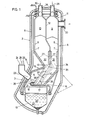
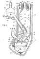
- FIGS. 1 and 2 each representing an embodiment in vertical section through a shaft carburetor.
- the shaft carburetor 1 has a vertical upper section 2, preferably having a circular cross section, and a laterally angled lower section 3, which forms the primary gas chamber 4. Since the shaft carburetor 1 can be used without pressure or under pressure, its outer jacket 5 is designed accordingly, that is to say as a pressure vessel or as an ordinary gas-tight vessel
- a container 8 having cooled walls 6, in particular walls 6 composed of tubes 7 through which coolant flows and constructed as a basket.
- the part of the basket 8 located within the vertical portion 2 of the shaft gasifier 1 has to form two compartments 9, 10 a from the upper end 1 1 of the basket 8 after cooled down to extending partition wall 1 2, whose lower free edge 1 3 for example in the height of the connection 14 of the angled lower section 3 of the shaft gasifier is located at the vertical part 2 thereof.
- the basket also has an inwardly projecting projection 15, which forms the upper boundary of the primary gas chamber 4 underneath
- the lower end 16 of the basket 8 is formed by a substantially horizontally directed supporting base 1 to 7, which also has a coolant and whose free, projecting into the primary gas chamber end is formed as a slag overflow weir 18 below the support base 17 is provided a trough 19 which with Coolant 20 for granulating the slag 22 which passes over the overflow weir and exits the primary gas chamber 4 through a through-opening 2 1 is filled
- a burner 23 opens into the primary gas chamber 4 above the slag waste bed 18, and feeds 24, 25, 26 for fuels, oxygen (or air) and possibly water vapor open into the burner.
- the basket 8 is coated on the inside up to the height of the first third of its vertical part — its partition 1 2 on both sides — with refractory material 27.
- the two compartments 9, 10 of the basket 8 each have at their upper end closable feed openings 29, 30 for the goods 31, 32 to be charged, by means of a lock 28.
- the section 9 located further away from the burner 23 is provided near the upper end 11 with a gas discharge line 33 for the product gas formed and opens into the primary gas chamber 4 by means of a passage 34.
- the section 10 located closer to the burner 23 opens into the primary gas chamber 4 with one Passage 34 adjacent charging opening 35th
- Charge material 32 to be gasified is then introduced into the section 10 of the basket 8 closer to the burner 23, which charge material 32 forms a further bed of bulk goods, which covers the first bed of bulk goods and has a free bed surface 38 facing the burner, against which the burner jet 39 is directed .
- the charge material 32 to be gasified which is introduced into the section 10 closer to the burner 23 can be of inferior quality, for example lignite, highly volatile hard coal or used tires.
- This charge is gasified after the burner 23 is ignited, the water vapor contained in the charge taking part in the gasification reactions and higher hydrocarbons being cracked from the pyrolysis and the resulting raw gas being forced as a result of the arrangement of the gas discharge line 33 in the section 9 lying away from the burner to pass through the bulk bed of coke 31 behind it.
- the raw gas is filtered so that the raw gas leaving the department 9 has a high purity; above all, it is free of higher hydrocarbons.
- the thickness 40 of the bulk material bed of the charge material 32 to be gasified depends on the thickness 40 of the bulk material bed of the charge material 32 to be gasified and on the setting of the primary gasification whether the charge material lying behind the second bulk material bed, e.g. the coke, also gasified or used only or primarily as a filter for the raw gas passing through.
- the primary gasification is adjusted either via the ratio of oxygen to carbon carrier in the burner, or via the total amount of primary gasification substances, or - if pure oxygen is introduced via the burner instead of air - via the ratio of oxygen to water vapor.
- the thickness 40 of the second bed of bulk material of the charging material 32 to be gasified and thus gasification of the charging material 31 lying behind it is influenced.
- a feed line 41 for the charge material 32 to be gasified opens into the vertical part 2 of the shaft gasifier 1, which leads from a container 42 connected to this feed line 41 by means of a conveying device, such as a screw conveyor 43, to form a bulk material bed the primary gas chamber 4 flows.
- the partition 12 ′ is directed obliquely downwards, preferably from the burner-side wall 44 of the basket 8, preferably at an angle of 30 to 45 ° to the primary gas chamber 4, in order to form the two bulk beds.
- the cargo to be gasified 32 slides through the feed line 41 via a sliding surface 45, which is cooled and provided with a refractory lining, up to the charging opening opening into the primary gas chamber 4.
- Sewage sludge, paper mache or dust-like fuel can also be fed to the burner 23 in pasty form.
- Waste oil in an amount of 3800 kg, pasty residue in an amount of 1 258 kg and air preheated to 500 ° C. in an amount of 32,000 Nm 3 were fed in per hour
- the primary gas generated by combustion in the burner was 38.18 1 Nm 3 / h (moist) at a temperature of 1510 ° C.
- the primary gas reacts with the batch 32 to be gasified, which consists of used tires (analysis in Table III) and deinking sludge - a residue from processing paper with printing ink and fillers - (chemical analysis in Table IV) Raw gas.
- Used tires were used in an amount of 1300 kg / h and deinking sludge in an amount of 2560 kg / h.
- the raw gas was 864 ° C when it entered the second bulk bed.
- the raw gas then flowed through the bulk bed of coke and was withdrawn as finished product gas in an amount of 46,924 Nm 3 / h. Its analysis is shown in Table V.
- the thermal efficiency in the process which is defined as the ratio of the product gas quantity times the product gas calorific value increased by the sensible heat of the product gas to the sum of the amount of the input materials times their respective calorific value, was 91%.
- the gasification efficiency which is defined as the ratio of the amount of product gas multiplied by the product gas calorific value to the sum of the amount of the feed materials times their respective calorific value, was 73%.
- the calorific value of the product gas was 949 kcal / Nm 3 .
- glassy solidified granulated slag was obtained in an amount of 1408 kg / h.
- the device was operated at a pressure of 4 bar.
- Waste oil was fed to the burner in an amount of 1800 kg / h and preferably air preheated to a temperature between 100 and 500 ° C. in an amount of 27906 Nm 3 / h.
- So-called BRAM - fuel from waste
- the consumption of coke as a charging material was 399 kg / h.
- the resulting raw gas was produced in an amount of 45500 Nm '/ h.
- Tables Vi to IX below show the analytical values for the waste oil, the BRAM, the product gas and the coke.
Landscapes
- Chemical & Material Sciences (AREA)
- Engineering & Computer Science (AREA)
- Combustion & Propulsion (AREA)
- Oil, Petroleum & Natural Gas (AREA)
- Organic Chemistry (AREA)
- Chemical Kinetics & Catalysis (AREA)
- General Chemical & Material Sciences (AREA)
- Gasification And Melting Of Waste (AREA)
- Processing Of Solid Wastes (AREA)
Applications Claiming Priority (2)
| Application Number | Priority Date | Filing Date | Title |
|---|---|---|---|
| AT0069585A AT382388B (de) | 1985-03-08 | 1985-03-08 | Vorrichtung zur vergasung von brennstoffen |
| AT695/85 | 1985-03-08 |
Publications (3)
| Publication Number | Publication Date |
|---|---|
| EP0194252A2 true EP0194252A2 (fr) | 1986-09-10 |
| EP0194252A3 EP0194252A3 (en) | 1987-05-06 |
| EP0194252B1 EP0194252B1 (fr) | 1989-02-01 |
Family
ID=3497387
Family Applications (1)
| Application Number | Title | Priority Date | Filing Date |
|---|---|---|---|
| EP86890048A Expired EP0194252B1 (fr) | 1985-03-08 | 1986-03-06 | Installation pour gazéifier des combustibles |
Country Status (6)
| Country | Link |
|---|---|
| US (2) | US4960439A (fr) |
| EP (1) | EP0194252B1 (fr) |
| JP (1) | JPS61207491A (fr) |
| AT (1) | AT382388B (fr) |
| CA (1) | CA1274091A (fr) |
| DE (1) | DE3662006D1 (fr) |
Cited By (5)
| Publication number | Priority date | Publication date | Assignee | Title |
|---|---|---|---|---|
| EP0277935A1 (fr) * | 1987-01-29 | 1988-08-10 | VOEST-ALPINE INDUSTRIEANLAGENBAU GESELLSCHAFT m.b.H. | Procédé pour gazéifier des combustibles à l'aide d'oxygène dans un four droit |
| WO1988009363A1 (fr) | 1987-05-28 | 1988-12-01 | Valerio Tognazzo | Procede et machine de transformation de polluants ou de dechets combustibles en energie propre et en produits utilisables |
| DE4030554A1 (de) * | 1990-09-27 | 1992-04-09 | Bergmann Michael Dr | Verfahren und vorrichtung zur thermischen behandlung von abfallstoffen |
| WO1992006329A1 (fr) * | 1990-10-09 | 1992-04-16 | Voest-Alpine Industrieanlagenbau Gesellschaft M.B.H | Procede d'incineration de dechets |
| US6251148B1 (en) | 1991-07-15 | 2001-06-26 | John Brown Deutsche Entineering Gmbh | Process for producing synthetic gasses |
Families Citing this family (7)
| Publication number | Priority date | Publication date | Assignee | Title |
|---|---|---|---|---|
| AT387979B (de) * | 1986-12-18 | 1989-04-10 | Voest Alpine Ag | Verfahren und vorrichtung zum vergasen von minderwertigen brennstoffen |
| DE4123406C2 (de) * | 1991-07-15 | 1995-02-02 | Engineering Der Voest Alpine I | Verfahren zum Vergasen von minderwertigen festen Brennstoffen in einem schachtförmigen Vergasungsreaktor |
| AT397808B (de) * | 1992-04-22 | 1994-07-25 | Oemv Ag | Verfahren zur druckvergasung von organischen substanzen, z.b. kunststoffmischungen |
| JP2715809B2 (ja) * | 1992-06-15 | 1998-02-18 | 日本鋼管株式会社 | 廃棄物の溶融・ガス化装置 |
| US5464592A (en) * | 1993-11-22 | 1995-11-07 | Texaco Inc. | Gasifier throat |
| JP4843319B2 (ja) * | 2006-01-26 | 2011-12-21 | 株式会社日立ハイテクノロジーズ | 走査型電子顕微鏡 |
| CN106479572A (zh) * | 2015-08-28 | 2017-03-08 | 安徽友力节能设备有限公司 | 一种气化炉 |
Family Cites Families (9)
| Publication number | Priority date | Publication date | Assignee | Title |
|---|---|---|---|---|
| US815794A (en) * | 1904-04-22 | 1906-03-20 | Alberto Cerasoli | Gas-producer. |
| US2805188A (en) * | 1952-10-23 | 1957-09-03 | Koppers Co Inc | Process for producing synthesis gas and coke |
| US4323366A (en) * | 1978-12-29 | 1982-04-06 | Voest-Alpine Ag | Apparatus for the gasification of coal |
| CH644149A5 (de) * | 1978-12-29 | 1984-07-13 | Voest Alpine Ag | Verfahren und vorrichtung zur vergasung von kohle. |
| FR2468377A1 (fr) * | 1979-11-06 | 1981-05-08 | Bourdon Frederic | Seringue a fonctionnement assiste par une source exterieure d'energie |
| JPS5770187A (en) * | 1980-10-20 | 1982-04-30 | Sumitomo Metal Ind Ltd | Gasifying method for coal by fixed bed furnace |
| DE3132506A1 (de) * | 1981-08-18 | 1983-03-03 | Hoechst Ag, 6000 Frankfurt | Verfahren und vorrichtung zur herstellung von synthesegas |
| JPS5839464A (ja) * | 1981-09-04 | 1983-03-08 | Silver Seiko Ltd | 印字装置 |
| AT388925B (de) * | 1987-01-29 | 1989-09-25 | Voest Alpine Ind Anlagen | Verfahren zum vergasen von brennstoffen mit sauerstoff in einem schachtfoermigen ofen |
-
1985
- 1985-03-08 AT AT0069585A patent/AT382388B/de not_active IP Right Cessation
-
1986
- 1986-03-06 EP EP86890048A patent/EP0194252B1/fr not_active Expired
- 1986-03-06 DE DE8686890048T patent/DE3662006D1/de not_active Expired
- 1986-03-07 JP JP61051278A patent/JPS61207491A/ja active Pending
- 1986-03-07 CA CA000503580A patent/CA1274091A/fr not_active Expired
-
1988
- 1988-08-12 US US07/291,402 patent/US4960439A/en not_active Expired - Fee Related
-
1989
- 1989-03-15 US US07/323,883 patent/US4941890A/en not_active Expired - Fee Related
Cited By (7)
| Publication number | Priority date | Publication date | Assignee | Title |
|---|---|---|---|---|
| EP0277935A1 (fr) * | 1987-01-29 | 1988-08-10 | VOEST-ALPINE INDUSTRIEANLAGENBAU GESELLSCHAFT m.b.H. | Procédé pour gazéifier des combustibles à l'aide d'oxygène dans un four droit |
| US4776285A (en) * | 1987-01-29 | 1988-10-11 | Voest-Alpine Aktiengesellschaft | Process for gasifying fuels with oxygen or oxygen-containing gases to be carried out in a shaft-like furnace arrangement |
| AT388925B (de) * | 1987-01-29 | 1989-09-25 | Voest Alpine Ind Anlagen | Verfahren zum vergasen von brennstoffen mit sauerstoff in einem schachtfoermigen ofen |
| WO1988009363A1 (fr) | 1987-05-28 | 1988-12-01 | Valerio Tognazzo | Procede et machine de transformation de polluants ou de dechets combustibles en energie propre et en produits utilisables |
| DE4030554A1 (de) * | 1990-09-27 | 1992-04-09 | Bergmann Michael Dr | Verfahren und vorrichtung zur thermischen behandlung von abfallstoffen |
| WO1992006329A1 (fr) * | 1990-10-09 | 1992-04-16 | Voest-Alpine Industrieanlagenbau Gesellschaft M.B.H | Procede d'incineration de dechets |
| US6251148B1 (en) | 1991-07-15 | 2001-06-26 | John Brown Deutsche Entineering Gmbh | Process for producing synthetic gasses |
Also Published As
| Publication number | Publication date |
|---|---|
| US4960439A (en) | 1990-10-02 |
| CA1274091A (fr) | 1990-09-18 |
| EP0194252B1 (fr) | 1989-02-01 |
| EP0194252A3 (en) | 1987-05-06 |
| AT382388B (de) | 1987-02-25 |
| ATA69585A (de) | 1986-07-15 |
| US4941890A (en) | 1990-07-17 |
| DE3662006D1 (en) | 1989-03-09 |
| JPS61207491A (ja) | 1986-09-13 |
Similar Documents
| Publication | Publication Date | Title |
|---|---|---|
| DE3685559T2 (de) | Zweistufiges kohlenvergasungsverfahren. | |
| EP0194252B1 (fr) | Installation pour gazéifier des combustibles | |
| DE3732867A1 (de) | Verfahren und vorrichtung zum erzeugen von generatorgas und aktivierter kohle aus festen brennstoffen | |
| DE2640180B2 (de) | Verfahren und Vorrichtung zum Vergasen fester Brennstoffe | |
| DE60033782T2 (de) | Verfahren zur vergasung von kohlenstoffhaltigen treibstoffen in einem festbettvergaser | |
| WO1981000112A1 (fr) | Procede et installation pour la gazeification de combustibles en morceaux | |
| DE3335544A1 (de) | Reaktorvorrichtung zur erzeugung von generatorgas aus brennbaren abfallprodukten | |
| DE4123406C2 (de) | Verfahren zum Vergasen von minderwertigen festen Brennstoffen in einem schachtförmigen Vergasungsreaktor | |
| DD227594A3 (de) | Schnellpyrolyse von braunkohlen und anordnung zur durchfuehrung des verfahrens | |
| DE2419517C3 (de) | Verfahren und Vorrichtung zum Herstellen von Reduktionsgas | |
| DE3614048A1 (de) | Verfahren und vorrichtung zur vergasung minderwertiger brennstoffe in einem feuerfluessigen metallschmelzbad | |
| EP0277935B1 (fr) | Procédé pour gazéifier des combustibles à l'aide d'oxygène dans un four droit | |
| DE3628102A1 (de) | Vorrichtung und verfahren zur herstellung von geschmolzenem eisen | |
| DE2947880A1 (de) | Verfahren zum vergasen von pelletisierten kohlenstoffhaltigen brennstoffen | |
| WO2007090585A1 (fr) | Procede et reacteur de gazeification avec extraction du laitier liquide | |
| DE3530240C2 (de) | Verfahren zum Schmelzen von zumindest teilweise reduziertem Eisenerz, sowie Vorrichtung zur Durchführung dieses Verfahrens | |
| DE3239624A1 (de) | Gasgenerator | |
| DE2857286A1 (de) | Kohlevergasungsverfahren und vorrichtung dafuer | |
| DE2909657C2 (de) | Verfahren und Vorrichtung zur Vergasung von körnigem Brennstoff | |
| DE102018205115B4 (de) | Festbettvergaser zum Erzeugen eines Produktgases aus schüttbaren Biomasseteilchen | |
| DE2747571A1 (de) | Verfahren zum kontinuierlichen erzeugen eines reduktionsgases und vorrichtung zum durchfuehren des verfahrens | |
| WO1987005634A1 (fr) | Procede et dispositif pour la gazeification d'un bain de fusion | |
| AT388169B (de) | Verfahren zum vergasen von brennstoffen | |
| DE19830069A1 (de) | Gaserzeuger | |
| DE19720331A1 (de) | Verfahren und Vorrichtung zur Entgasung und Vergasung oder Verbrennung |
Legal Events
| Date | Code | Title | Description |
|---|---|---|---|
| PUAI | Public reference made under article 153(3) epc to a published international application that has entered the european phase |
Free format text: ORIGINAL CODE: 0009012 |
|
| AK | Designated contracting states |
Kind code of ref document: A2 Designated state(s): BE CH DE FR GB IT LI LU NL SE |
|
| PUAL | Search report despatched |
Free format text: ORIGINAL CODE: 0009013 |
|
| AK | Designated contracting states |
Kind code of ref document: A3 Designated state(s): BE CH DE FR GB IT LI LU NL SE |
|
| 17P | Request for examination filed |
Effective date: 19870727 |
|
| 17Q | First examination report despatched |
Effective date: 19880705 |
|
| RAP1 | Party data changed (applicant data changed or rights of an application transferred) |
Owner name: VOEST-ALPINE INDUSTRIEANLAGENBAU GESELLSCHAFT M.B. |
|
| GRAA | (expected) grant |
Free format text: ORIGINAL CODE: 0009210 |
|
| AK | Designated contracting states |
Kind code of ref document: B1 Designated state(s): BE CH DE FR GB IT LI LU NL SE |
|
| REF | Corresponds to: |
Ref document number: 3662006 Country of ref document: DE Date of ref document: 19890309 |
|
| ET | Fr: translation filed | ||
| PG25 | Lapsed in a contracting state [announced via postgrant information from national office to epo] |
Ref country code: LU Free format text: LAPSE BECAUSE OF NON-PAYMENT OF DUE FEES Effective date: 19890331 |
|
| GBT | Gb: translation of ep patent filed (gb section 77(6)(a)/1977) | ||
| ITF | It: translation for a ep patent filed | ||
| PLBE | No opposition filed within time limit |
Free format text: ORIGINAL CODE: 0009261 |
|
| STAA | Information on the status of an ep patent application or granted ep patent |
Free format text: STATUS: NO OPPOSITION FILED WITHIN TIME LIMIT |
|
| 26N | No opposition filed | ||
| PGFP | Annual fee paid to national office [announced via postgrant information from national office to epo] |
Ref country code: LU Payment date: 19900222 Year of fee payment: 5 |
|
| PGFP | Annual fee paid to national office [announced via postgrant information from national office to epo] |
Ref country code: SE Payment date: 19920217 Year of fee payment: 7 Ref country code: GB Payment date: 19920217 Year of fee payment: 7 Ref country code: CH Payment date: 19920217 Year of fee payment: 7 |
|
| PGFP | Annual fee paid to national office [announced via postgrant information from national office to epo] |
Ref country code: BE Payment date: 19920218 Year of fee payment: 7 |
|
| PGFP | Annual fee paid to national office [announced via postgrant information from national office to epo] |
Ref country code: FR Payment date: 19920221 Year of fee payment: 7 |
|
| ITTA | It: last paid annual fee | ||
| PGFP | Annual fee paid to national office [announced via postgrant information from national office to epo] |
Ref country code: NL Payment date: 19920331 Year of fee payment: 7 |
|
| PG25 | Lapsed in a contracting state [announced via postgrant information from national office to epo] |
Ref country code: GB Effective date: 19930306 |
|
| PG25 | Lapsed in a contracting state [announced via postgrant information from national office to epo] |
Ref country code: SE Effective date: 19930307 |
|
| PG25 | Lapsed in a contracting state [announced via postgrant information from national office to epo] |
Ref country code: LI Effective date: 19930331 Ref country code: CH Effective date: 19930331 Ref country code: BE Effective date: 19930331 |
|
| BERE | Be: lapsed |
Owner name: VOEST-ALPINE INDUSTRIEANLAGENBAU G.M.B.H. Effective date: 19930331 |
|
| PG25 | Lapsed in a contracting state [announced via postgrant information from national office to epo] |
Ref country code: NL Effective date: 19931001 |
|
| GBPC | Gb: european patent ceased through non-payment of renewal fee |
Effective date: 19930306 |
|
| NLV4 | Nl: lapsed or anulled due to non-payment of the annual fee | ||
| PG25 | Lapsed in a contracting state [announced via postgrant information from national office to epo] |
Ref country code: FR Effective date: 19931130 |
|
| REG | Reference to a national code |
Ref country code: CH Ref legal event code: PL |
|
| REG | Reference to a national code |
Ref country code: FR Ref legal event code: ST |
|
| EUG | Se: european patent has lapsed |
Ref document number: 86890048.1 Effective date: 19931008 |
|
| PGFP | Annual fee paid to national office [announced via postgrant information from national office to epo] |
Ref country code: DE Payment date: 19970220 Year of fee payment: 12 |
|
| PG25 | Lapsed in a contracting state [announced via postgrant information from national office to epo] |
Ref country code: DE Free format text: LAPSE BECAUSE OF NON-PAYMENT OF DUE FEES Effective date: 19981201 |
|
| PG25 | Lapsed in a contracting state [announced via postgrant information from national office to epo] |
Ref country code: IT Free format text: LAPSE BECAUSE OF NON-PAYMENT OF DUE FEES Effective date: 20050306 |