EP0194322B1 - Walzwerk - Google Patents
Walzwerk Download PDFInfo
- Publication number
- EP0194322B1 EP0194322B1 EP85102468A EP85102468A EP0194322B1 EP 0194322 B1 EP0194322 B1 EP 0194322B1 EP 85102468 A EP85102468 A EP 85102468A EP 85102468 A EP85102468 A EP 85102468A EP 0194322 B1 EP0194322 B1 EP 0194322B1
- Authority
- EP
- European Patent Office
- Prior art keywords
- crown
- rolls
- plate
- roll
- given
- Prior art date
- Legal status (The legal status is an assumption and is not a legal conclusion. Google has not performed a legal analysis and makes no representation as to the accuracy of the status listed.)
- Expired
Links
Images



Classifications
-
- B—PERFORMING OPERATIONS; TRANSPORTING
- B21—MECHANICAL METAL-WORKING WITHOUT ESSENTIALLY REMOVING MATERIAL; PUNCHING METAL
- B21B—ROLLING OF METAL
- B21B37/00—Control devices or methods specially adapted for metal-rolling mills or the work produced thereby
- B21B37/28—Control of flatness or profile during rolling of strip, sheets or plates
- B21B37/30—Control of flatness or profile during rolling of strip, sheets or plates using roll camber control
Definitions
- the present invention relates to a rolling mill for metal stocks, and more particularly to a rolling mill which over a wide range can control the plate crown.
- the work rolls are subjected to a large rolling load which causes a deflection of the rolls, while the portion of the roll surface which is in contact with the rolling stock is forced to be flat.
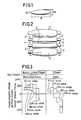
- the edges of the plate being rolled are extended sidewise so that the distribution of thickness of the rolled plate in the direction of the roll axis will be as shown in Fig. 1, leaving the thickest portion in the rolled center of the plate, which gradually becomes thinner toward the plate edges.
- This is the phenomenon of plate crown usually seen in the conventional rolling mill operation.
- the amount of the plate crown varies depending on the rolling variables, the thermal expansion of the rolls and the roll wear.
- Fig. 1 B represents the plate which, tM represents the thickness of the rolled center of the plate, tE represents the thickness of the plate edges, and the plate crown is represented by tM-tE.
- Fig. 3 shows the controllability range of plate crown defined by roll deformation under uniform force (herein called the controllability range of plate crown under uniform force) obtainable by various crown values given to the back-up rolls.
- the plate crown under uniform force means a calculated plate crown from the plate thickness distribution defined by the shape of work rolls determined by the deformation of the rolls caused by the load acting on the rolls imposed by the mill stand, which load is assumed to be distributed uniformly across the width of the plate being rolled.
- This calculated plate crown is not identical to the actual plate crown, but is very useful for relative comparison of the plate crown controllability of rolling mills.
- the EP-A-0 124 991 describes a rolling mill and a method of reducing metal work.
- the rolling mill comprises a housing mounting a pair of cooperating work rolls and a back-up roll for each work roll, the work roll bending equipment bends the work roll ends away from one another. At least one of the back-up rolls has an effective barrel length substantially shorter than the barrel length of the work roll with which it is in contact. There is also provided a load transmitting means for transmitting rolling load from the ends of the work roll to the housings.
- One object of the present invention is to provide a rolling mill which can effectively control the plate crown in plate rolling by overcoming the problems of the conventional arts in reducing and controlling the plate crown as aforementioned. This object is achieved by the features of the independent claims 1 and 2.
- the gist of the present invention lies in that a convex roll crown C SUR of 0.5 to 10 mm in diameter is given to at least one back-up roll which is in contact with one of a pair of upper and lower work rolls and a concave crown C WR is given to at least one of the work rolls under the condition:
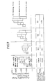
- Fig. 4 The results of the experiments made using the hot strip tandem mill with different roll crowns are shown in Fig. 4.
- the evaluations of the controllability range of plate crown under uniform force are: 0 represents satisfactory results, X represents the range being on the minus side and A represents the range being excessive on the plus side when the plate width is considerably wide. It is understood from Fig. 4 that if the concave crown of the work rolls is small, the resultant plate crown will be concave for a large width of plate, and on the other hand if the concave crown of the work rolls is too large, the plate crown controllability range will be excessively biased on the plus side.
- an increased amount of the convex crown given to the back-up roll will expand the controllability range of plate crown under uniform force, butthe increased amountwill cause a contact stress, (Hertz's contact stress), between the back-up rolls and the work rolls as shown in Fig. 6, and the maximum linear load is imposed on the rolled center of the plate as shown in Fig. 6(a), so that spalling will very readily occur.
- the roll bending force applied is 90 tons and the strip width used is 210 cm. Therefore, the amount of the maximum convex crown given to the back-up roll is naturally limited by the spalling limit, but this maximum crown amount limited by the spalling limit will, needless to say, be increased as the width of the plate being rolled increases.
- the maximum convex crown amount admitted to the back-up roll is determined by the spalling limit in the rolling of a maximum width of a given mill capacity.
- the limitforthe maximum crown amount beyond which the spalling is caused is about 10 mm. Therefore, the range of the convex crown given to the back-up roll should be not larger than 10 mm in diameter in view of the crown control effect and the spalling limit of the rolls.
- the back-up rolls are given a convex crown in view of the type of roll wears and other factors, but the crown in this case is about 0.2 mm at the largest point.
- the controllability range of plate crown under uniform force is 50 um or less.
- the plate crown of hot strip mill product in the range from 0 to 60 ⁇ m so as to meet with the requirements of the subsequent cold rolling operation, and forthis purpose the controllability range of plate crown under uniform force for each stand of the hot strip rolling tandem mill must be at least 60 ⁇ m with respect to a 90 cm width of plate.
- a convex crown of at least 0.5 mm in diameter must be given to the back-up rolls.
- the work rolls are given a convex or concave crown shape of about 0.1 mm in diameter in view of the wear and thermal expansion of the rolls.
- the work rolls are given a large concave crown ranging from 0.15x CBUR to 0.4xC BUR in diameter depending on the magnitude of the convex crown given to the back-up roll.
- Fig. 7 the controllability ranges of plate crown under uniform force from which the actual plate crown can be controlled to the range from 0 to 60 pm are shown. As shown a larger width of plate provides a wider controllability range.
- the controllability ranges of plate crown under uniform force achieved by the work and back-up rolls with appropriate crowns according to the present invention are shwon in Fig. 7 in comparison with those achieved without giving the crown to the back-up rolls.
- Fig. 7 when an appropriate concave crown satisfying the condition (1), depending on the magnitude of the convex crown given to the back-up rolls, a proper controllability range can be obtained for various widths of the plates being rolled, whereby problems such as the crown being controlled only on the minus side as shown in Fig. 3 can be eliminated and the controllability range of plate crown under uniform force can be expanded substantially.
- a shape of the roll crown various shapes such as crowns formed by straight lines (a), (b), a sine curve (c), and a parabola (d) shown in Fig. 8 may be used.
- a concave crown shape complementary to the convex crown shapes of the back-up rolls shown in Fig. 8 may be used.
- the crown shape as shown by (a), (b) and (e) in Fig. 8 are not desirable.
- the desired results of the present invention can be obtained also by a rolling mill arrangement in which an intermediate roll is mounted between the work roll and the back-up roll, and the intermediate roll is given a convex crown and the work roll is given a concave crown corresponding to the magnitude of the convex crown of the intermediate roll.
- an effective controllability range of plate crown under uniform force can be guaranteed for various widths by giving a convex crown to the back-up roll which is in contact with the work roll and giving a concave crown to the work roll depending on the magnitude of the convex crown of the back-up roll, and at the same time a remarkable plate crown controlling effect is obtained by the roll bending.
- a mill arrangement in which 6 to 7 stands are arranged adjacent each other is usually used.
- the work rolls and back-up rolls of at least one stand are given the crown configurations as defined in the present invention so as to control the plate crown of the final mill products. If the number of the stands in which the rolls are given the crown configurations according to the present invention is increased, the controlling capacity and ability are so much increased.
- Example of the mill arrangements composed of seven stands are illustrated in Fig. 9. The particulars of the mills are set forth below.
- the rolls are crowned according to the present invention.
- the roll stands designated (b) are conventional ones specially designed for the crown control.
- Fig. 9 The mill arrangements shown in Fig. 9 are used for the plate crown controlling of special grades of steel which are very rigid and difficult to control the plate crown.
- the conventional crown controlling rolling stands of high capital cost are arranged in the down-stream of the mill train, and the rolling stands according to the present invention are arranged in the up-stream of the train so that the capital cost as a whole is greatly reduced.
- the desired result can be obtained by only one stand as defined by the present invention incorporated in a mill comprising a plurality of stands.
- better results can be obtained by incorporating more than one stand according to the present invention.
- the present invention has advantages such that it can be put into commercial practice at very low capital costs and can be applied to existing mills without having to be rearranged, and yet a marked plate crown controlling effect can be obtained. Further, the expanded range of the crown controllability achieved by the present invention greatly contributes to the reduction of the crown of final mill products and to the improvement of the plate thickness accuracy, hence improvements of the product quality and production yield. Further, according to the present invention, as the necessity of changing the crown of the work rolls in accordance with the sizes of rolling products to be rolled is eliminated, the frequency of the work roll changing is substantially reduced so that marked economical advantages can be obtained from the aspects of energy saving efficiency and mill productivity.
Landscapes
- Engineering & Computer Science (AREA)
- Mechanical Engineering (AREA)
- Reduction Rolling/Reduction Stand/Operation Of Reduction Machine (AREA)
- Control Of Metal Rolling (AREA)
Claims (4)

Priority Applications (3)
| Application Number | Priority Date | Filing Date | Title |
|---|---|---|---|
| EP85102468A EP0194322B1 (de) | 1985-03-05 | 1985-03-05 | Walzwerk |
| DE8585102468T DE3564202D1 (en) | 1985-03-05 | 1985-03-05 | A rolling mill |
| AT85102468T ATE36256T1 (de) | 1985-03-05 | 1985-03-05 | Walzwerk. |
Applications Claiming Priority (1)
| Application Number | Priority Date | Filing Date | Title |
|---|---|---|---|
| EP85102468A EP0194322B1 (de) | 1985-03-05 | 1985-03-05 | Walzwerk |
Publications (2)
| Publication Number | Publication Date |
|---|---|
| EP0194322A1 EP0194322A1 (de) | 1986-09-17 |
| EP0194322B1 true EP0194322B1 (de) | 1988-08-10 |
Family
ID=8193347
Family Applications (1)
| Application Number | Title | Priority Date | Filing Date |
|---|---|---|---|
| EP85102468A Expired EP0194322B1 (de) | 1985-03-05 | 1985-03-05 | Walzwerk |
Country Status (3)
| Country | Link |
|---|---|
| EP (1) | EP0194322B1 (de) |
| AT (1) | ATE36256T1 (de) |
| DE (1) | DE3564202D1 (de) |
Family Cites Families (2)
| Publication number | Priority date | Publication date | Assignee | Title |
|---|---|---|---|---|
| DE1452153A1 (de) * | 1965-11-26 | 1968-12-12 | Verwaltungsgesellschaft Moelle | Walzwerk zur Herstellung von Flachprodukten,z.B. von Blechen und Baendern |
| GB8309021D0 (en) * | 1983-03-31 | 1983-05-11 | Davy Mckee Sheffield | Rolling mill |
-
1985
- 1985-03-05 EP EP85102468A patent/EP0194322B1/de not_active Expired
- 1985-03-05 AT AT85102468T patent/ATE36256T1/de not_active IP Right Cessation
- 1985-03-05 DE DE8585102468T patent/DE3564202D1/de not_active Expired
Also Published As
| Publication number | Publication date |
|---|---|
| DE3564202D1 (en) | 1988-09-15 |
| ATE36256T1 (de) | 1988-08-15 |
| EP0194322A1 (de) | 1986-09-17 |
Similar Documents
| Publication | Publication Date | Title |
|---|---|---|
| JPH0249161B2 (de) | ||
| US4528830A (en) | Method for changing widthwise distribution of thickness of metal strip | |
| US4596130A (en) | Rolling mill | |
| US5622073A (en) | Six high rolling mill | |
| EP0043869B2 (de) | Walze für Walzwerk | |
| AU731151B2 (en) | Roll stand for rolling strip | |
| EP0065930B1 (de) | Walzwerk | |
| US4407151A (en) | Rolling mill | |
| JPH0521653B2 (de) | ||
| EP0543014B1 (de) | Sechs-walzen-walzwerk | |
| JPS6210722B2 (de) | ||
| US4856313A (en) | Method of controlling strip crown in planetary rolling | |
| CA1241216A (en) | Rolling mill | |
| EP0194322A1 (de) | Walzwerk | |
| KR890004601B1 (ko) | 압연기 | |
| EP1188493B1 (de) | Regelverfahren zum Walzen eines Bandes in einem Walzgerüst | |
| JPH0620562B2 (ja) | 熱間圧延時の板クラウン制御方法 | |
| AU681219B2 (en) | H-steel manufacturing method | |
| CA1302743C (en) | Method of controlling strip crown in planetary rolling | |
| EP0072385B2 (de) | Vierwalzengerüst mit gekreuztem Walzenpaar | |
| EP0400568B1 (de) | Walzverfahren in einem Fünfwalzen-Walzwerk | |
| JPS6365403B2 (de) | ||
| JPH0523705A (ja) | 鋼板の圧延方法 | |
| KR19990052835A (ko) | 폭방향 두께품질이 우수한 압연방법 | |
| Ginzburg | Thinner hot strip by improving control on conventional mills |
Legal Events
| Date | Code | Title | Description |
|---|---|---|---|
| PUAI | Public reference made under article 153(3) epc to a published international application that has entered the european phase |
Free format text: ORIGINAL CODE: 0009012 |
|
| 17P | Request for examination filed |
Effective date: 19860528 |
|
| AK | Designated contracting states |
Kind code of ref document: A1 Designated state(s): AT BE DE FR GB IT NL |
|
| 17Q | First examination report despatched |
Effective date: 19870123 |
|
| GRAA | (expected) grant |
Free format text: ORIGINAL CODE: 0009210 |
|
| AK | Designated contracting states |
Kind code of ref document: B1 Designated state(s): AT BE DE FR GB IT NL |
|
| REF | Corresponds to: |
Ref document number: 36256 Country of ref document: AT Date of ref document: 19880815 Kind code of ref document: T |
|
| REF | Corresponds to: |
Ref document number: 3564202 Country of ref document: DE Date of ref document: 19880915 |
|
| ET | Fr: translation filed | ||
| ITF | It: translation for a ep patent filed | ||
| PLBI | Opposition filed |
Free format text: ORIGINAL CODE: 0009260 |
|
| 26 | Opposition filed |
Opponent name: SMS SCHLOEMANN-SIEMAG AG Effective date: 19890506 |
|
| NLR1 | Nl: opposition has been filed with the epo |
Opponent name: SMS SCHLOEMANN-SIEMAG AG |
|
| PLBN | Opposition rejected |
Free format text: ORIGINAL CODE: 0009273 |
|
| STAA | Information on the status of an ep patent application or granted ep patent |
Free format text: STATUS: OPPOSITION REJECTED |
|
| 27O | Opposition rejected |
Effective date: 19900802 |
|
| NLR2 | Nl: decision of opposition | ||
| ITTA | It: last paid annual fee | ||
| PGFP | Annual fee paid to national office [announced via postgrant information from national office to epo] |
Ref country code: FR Payment date: 19960126 Year of fee payment: 12 |
|
| PGFP | Annual fee paid to national office [announced via postgrant information from national office to epo] |
Ref country code: GB Payment date: 19960226 Year of fee payment: 12 |
|
| PGFP | Annual fee paid to national office [announced via postgrant information from national office to epo] |
Ref country code: DE Payment date: 19960313 Year of fee payment: 12 Ref country code: AT Payment date: 19960313 Year of fee payment: 12 |
|
| PGFP | Annual fee paid to national office [announced via postgrant information from national office to epo] |
Ref country code: NL Payment date: 19960328 Year of fee payment: 12 |
|
| PGFP | Annual fee paid to national office [announced via postgrant information from national office to epo] |
Ref country code: BE Payment date: 19960502 Year of fee payment: 12 |
|
| PG25 | Lapsed in a contracting state [announced via postgrant information from national office to epo] |
Ref country code: GB Effective date: 19970305 Ref country code: AT Effective date: 19970305 |
|
| PG25 | Lapsed in a contracting state [announced via postgrant information from national office to epo] |
Ref country code: BE Effective date: 19970331 |
|
| BERE | Be: lapsed |
Owner name: NIPPON STEEL CORP. Effective date: 19970331 |
|
| PG25 | Lapsed in a contracting state [announced via postgrant information from national office to epo] |
Ref country code: NL Effective date: 19971001 |
|
| GBPC | Gb: european patent ceased through non-payment of renewal fee |
Effective date: 19970305 |
|
| PG25 | Lapsed in a contracting state [announced via postgrant information from national office to epo] |
Ref country code: FR Free format text: LAPSE BECAUSE OF NON-PAYMENT OF DUE FEES Effective date: 19971128 |
|
| NLV4 | Nl: lapsed or anulled due to non-payment of the annual fee |
Effective date: 19971001 |
|
| PG25 | Lapsed in a contracting state [announced via postgrant information from national office to epo] |
Ref country code: DE Effective date: 19971202 |
|
| REG | Reference to a national code |
Ref country code: FR Ref legal event code: ST |