EP0194330A1 - Verfahren zum Ersetzen von Schrauben eines bestrahlten Brennstoffbündels und Anordnung zur Verwendung dieses Verfahrens - Google Patents
Verfahren zum Ersetzen von Schrauben eines bestrahlten Brennstoffbündels und Anordnung zur Verwendung dieses Verfahrens Download PDFInfo
- Publication number
- EP0194330A1 EP0194330A1 EP85102875A EP85102875A EP0194330A1 EP 0194330 A1 EP0194330 A1 EP 0194330A1 EP 85102875 A EP85102875 A EP 85102875A EP 85102875 A EP85102875 A EP 85102875A EP 0194330 A1 EP0194330 A1 EP 0194330A1
- Authority
- EP
- European Patent Office
- Prior art keywords
- screw
- screws
- guide plate
- guide
- clamping flange
- Prior art date
- Legal status (The legal status is an assumption and is not a legal conclusion. Google has not performed a legal analysis and makes no representation as to the accuracy of the status listed.)
- Withdrawn
Links
- 238000000034 method Methods 0.000 title claims description 15
- 239000000446 fuel Substances 0.000 title description 3
- 238000002788 crimping Methods 0.000 claims description 12
- 238000003754 machining Methods 0.000 claims description 11
- 239000002699 waste material Substances 0.000 claims description 4
- 230000000717 retained effect Effects 0.000 claims description 3
- 238000007789 sealing Methods 0.000 claims description 2
- 238000003466 welding Methods 0.000 claims 1
- 239000003758 nuclear fuel Substances 0.000 abstract 1
- 230000000712 assembly Effects 0.000 description 4
- 238000000429 assembly Methods 0.000 description 4
- XLYOFNOQVPJJNP-UHFFFAOYSA-N water Substances O XLYOFNOQVPJJNP-UHFFFAOYSA-N 0.000 description 3
- 238000009434 installation Methods 0.000 description 2
- 230000000284 resting effect Effects 0.000 description 2
- 238000000926 separation method Methods 0.000 description 2
- 230000009182 swimming Effects 0.000 description 2
- 230000015572 biosynthetic process Effects 0.000 description 1
- 230000009849 deactivation Effects 0.000 description 1
- 238000007599 discharging Methods 0.000 description 1
- 238000000605 extraction Methods 0.000 description 1
- 238000007373 indentation Methods 0.000 description 1
- 238000012423 maintenance Methods 0.000 description 1
- 238000003801 milling Methods 0.000 description 1
- 238000001356 surgical procedure Methods 0.000 description 1
Images



Classifications
-
- F—MECHANICAL ENGINEERING; LIGHTING; HEATING; WEAPONS; BLASTING
- F16—ENGINEERING ELEMENTS AND UNITS; GENERAL MEASURES FOR PRODUCING AND MAINTAINING EFFECTIVE FUNCTIONING OF MACHINES OR INSTALLATIONS; THERMAL INSULATION IN GENERAL
- F16B—DEVICES FOR FASTENING OR SECURING CONSTRUCTIONAL ELEMENTS OR MACHINE PARTS TOGETHER, e.g. NAILS, BOLTS, CIRCLIPS, CLAMPS, CLIPS OR WEDGES; JOINTS OR JOINTING
- F16B39/00—Locking of screws, bolts or nuts
- F16B39/02—Locking of screws, bolts or nuts in which the locking takes place after screwing down
- F16B39/10—Locking of screws, bolts or nuts in which the locking takes place after screwing down by a plate, spring, wire or ring immovable with regard to the bolt or object and mainly perpendicular to the axis of the bolt
- F16B39/103—Locking of screws, bolts or nuts in which the locking takes place after screwing down by a plate, spring, wire or ring immovable with regard to the bolt or object and mainly perpendicular to the axis of the bolt with a locking cup washer, ring or sleeve surrounding the nut or bolt head and being partially deformed on the nut or bolt head, or on the object itself
- F16B39/105—Locking of screws, bolts or nuts in which the locking takes place after screwing down by a plate, spring, wire or ring immovable with regard to the bolt or object and mainly perpendicular to the axis of the bolt with a locking cup washer, ring or sleeve surrounding the nut or bolt head and being partially deformed on the nut or bolt head, or on the object itself locking the bold head or nut into a hole or cavity, e.g. with the cup washer, ring or sleeve deformed into a dimple in the cavity
-
- G—PHYSICS
- G21—NUCLEAR PHYSICS; NUCLEAR ENGINEERING
- G21C—NUCLEAR REACTORS
- G21C19/00—Arrangements for treating, for handling, or for facilitating the handling of, fuel or other materials which are used within the reactor, e.g. within its pressure vessel
- G21C19/26—Arrangements for removing jammed or damaged fuel elements or control elements; Arrangements for moving broken parts thereof
-
- G—PHYSICS
- G21—NUCLEAR PHYSICS; NUCLEAR ENGINEERING
- G21C—NUCLEAR REACTORS
- G21C3/00—Reactor fuel elements and their assemblies; Selection of substances for use as reactor fuel elements
- G21C3/30—Assemblies of a number of fuel elements in the form of a rigid unit
- G21C3/32—Bundles of parallel pin-, rod-, or tube-shaped fuel elements
- G21C3/334—Assembling, maintenance or repair of the bundles
-
- Y—GENERAL TAGGING OF NEW TECHNOLOGICAL DEVELOPMENTS; GENERAL TAGGING OF CROSS-SECTIONAL TECHNOLOGIES SPANNING OVER SEVERAL SECTIONS OF THE IPC; TECHNICAL SUBJECTS COVERED BY FORMER USPC CROSS-REFERENCE ART COLLECTIONS [XRACs] AND DIGESTS
- Y02—TECHNOLOGIES OR APPLICATIONS FOR MITIGATION OR ADAPTATION AGAINST CLIMATE CHANGE
- Y02E—REDUCTION OF GREENHOUSE GAS [GHG] EMISSIONS, RELATED TO ENERGY GENERATION, TRANSMISSION OR DISTRIBUTION
- Y02E30/00—Energy generation of nuclear origin
- Y02E30/30—Nuclear fission reactors
Definitions
- the invention relates to a method for replacing the screws of the clamps of an irradiated and submerged fuel assembly in a deactivation pool. This process consists of removing by machining, in the immediate vicinity of the screw to be replaced, crimping lugs used to immobilize a cup folded over the replacement screw.
- the invention also relates to a device designed for implementing the method.
- This device mainly comprises a guide plate located at its base and used to anchor the device on the assembly, to position the various tools and to convey the waste from the machining to a central tube, of great length, serving both to the suction of the water and the positioning of guide plates supporting the long tool bodies using bearings.
- each screw In nuclear power plant equipment, each screw is protected against accidental loosening and separation of the head in the event of rupture.
- One of the means commonly used is to drive a pin into a notch in the screw head and weld the ends to the part immediately adjacent to the head of the screw.
- the present invention aims to remedy these drawbacks.
- the method as characterized in the claims consists in removing the broken screw by destroying the weld spots, which hold the ends of the spindle in the recess of the screw, using a bell-shaped cutter then to be machined by electro-erosion of the crimping lugs used to immobilize the tail of a cup whose upper edge of the cylindrical part is folded over the screw head.
- This process is carried out entirely under water; it applies not only during an accidental replacement of a broken screw but also during a campaign aimed at replacing a quality of screw deemed unsuitable for certain operating conditions.
- the device as characterized in the claims consists in having at its base a guide plate provided with retractable pins, serving to anchor the device on the assembly, guide holes, serving to position the tools, and channels evacuation conveyor of the waste and machining gifts to a central suction tube on which at regular intervals are arranged guide plates provided with bearings aligned on the guide holes to support the bodies of very long tools at l using sleeves placed at the desired height.
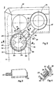
- Figure 1 shows a frame 1, of square shape, located at the top of the assembly and carrying two clamps 2 and 3 arranged in two opposite corners of the frame 1 to ensure the maintenance of two leaf springs 4 and 5
- the flange 2 provided with an additional hole acting as a keying device 6 is held by screws 7 and 8, the heads of which bear imprints in the form of a cross.
- a pin 9 In one of the imprints of the screw 7 is engaged a pin 9, the two ends 11 and 12 of which are welded in a recess 13.
- a impression of the screw 8 receives a pin 10 welded by its two ends 14 and 15 to a recess 16.
- Figure 2 shows the clamp 2 after a series of machining operations which will be detailed later. These operations are successively: releasing the screw heads by destroying by milling the probing points which retain the pins in the recesses, forming recesses 20 and 21 of larger diameter and freeing by electro-erosion of the crimping lugs 22,23, 24.25 in the mass of the clamp 2.
- FIG. 2 Also shown in FIG. 2 are a cup 26 provided with a shank 27 and a replacement screw 28 screwed into the recess 20.
- the replacement screw 28 has indentations 29 in which the upper edge of the cup 26 when it is folded down, and imprints 30 used for screwing and unscrewing.
- the clamping flange 2 has chamfers 31 and 32 intended to facilitate the installation of neighboring assemblies.
- Figure 3 shows a section along section AB of the cup 26 and its tail 27.
- This cup 26, introduced into the recess 20, is oriented so that the tail 27 comes to rest between the two crimp tabs 22 and 23
- the cylindrical part of the cup 26 is partially amputated on the sector arranged along the chamfer 31 of FIG. 2.
- Figure 4 shows a section along the section CD of the tail 27 and the crimping lugs 22 and 23. These lugs were obtained by electro-erosion using an electrode whose shape allowed the simultaneous knockout of the notches 33, 34 and 35 along a width and a depth allowing the tail 27 to be retained by bringing the legs 22 and 23 together.
- FIG. 5 represents a section in elevation along section AB of a part of the clamping flange 2 after the replacement screw 28 has been put in place and the upper edge of the cup 26 has been folded down to fit into the cavity 29 the replacement screw 28.
- FIG. 5 also shows the folded crimping tab, as suggested in FIG. 4, for retaining the tail 27.
- An intervention device 40 for replacing the screws of the submerged assemblies comprises a guide plate 41 having the general appearance of a square, the angles of which are reinforced by corner elements. These four corner elements are distributed in a first pair of positioning elements 42 and 43 of the device 40 and in a second pair of guide elements 44 and 45 of the tools.
- Figure 7 it should be noted that it represents in its right part a section in elevation made along the axis EF and that in its left part appears a partial section made along the axis GH.
- the guide plate 41 is provided with two discharge channels 46. And 47 joining a central chamber 48 at the periphery of the guide plate, each passing through a guide hole 49 for the guide element 45 and through a guide hole. 50 for the guide element 44.
- the guide hole 49 carries a chamfer 49 'and the guide hole 50 carries a chamfer 50' which serve to facilitate the centering of the tools in line with the screws for which it is necessary to intervene.
- a square-shaped plug 52 placed under the guide plate 41 connects the latter to a round plate serving as a foot 53 for a tube central vacuum unit 54 using four screws 55.
- This plug 52 is placed on the frame 1 of FIG. 1 while the two guide elements 44 and 45 are posed on the clamps 2 and 3 and that the two positioning elements 42 and 43 are posed on the elevations 17 and 18.
- Each retractable pin 56 is composed of a split socket 57 retained, in the case of FIG. 7 by a collar 58, to the positioning element 42 and fixed to the latter by a screw 59.
- this split socket 57 slides a pin 60 provided with an end in the form of two trunks of cones associated by the base and called expansion 61.
- the other end of the spindle 60 is threaded so as to collaborate with a nut 62 serving to raise the spindle 60 so that the opening 61 deforms the split bush 57 and ensures its jamming in the cylindrical bore of a locating hole 19.
- the guide hole 49 in Figure 6 is coaxial with the screw 8 in Figure 1.
- the guide hole 50 is coaxial with a screw 63 contributing with another screw 64 to the fixing of the clamping flange on the frame 1.
- the central suction tube 54 also serves as a support for guide plates 65 and 66.
- the guide plate 65 is equipped with a bearing 67, coaxial with the guide hole 49, which serves to maintain the alignment of the bodies d tools of great length.
- the guide plate 66 is equipped with a bearing 68 coaxial with the guide hole 50.
- the device 40 can occupy two distinct positions offset from each other by 180 ° by rotation about the axis " of the central suction tube 54.
- a first position corresponding to that of FIG. 6, makes it possible to work on screws 63 and 8.
- the other position obtained after rotation of 180 °, gives access to screws 64 and 7.
- central suction tube 54 Along the central suction tube 54 are positioned at regular intervals several pairs of guide plates, similar to the guide plates 65 and 66, to ensure the correct alignment of the tool bodies over the entire height of the device 40 which emerges at several meters above the foot 53 of the central suction tube 54.
- the foot 53 can be rotated relative to the guide plate 41 so as to separate the guide plates 65 and 66 from the guide elements 44 and 45 to give access to certain tools which cannot '' align the guide plates to the right.
- a pin 69 held by a chain 70 is inserted into different holes such as holes 71 or 72.
- the emerged part of the central suction tube 54 ensures the positioning of a work table for centering the upper end of the tools used.
- This emerged part of the eentral suction tube 54 also carries an elbow which diverts the water pipe towards a pump and a filter before discharging it into the swimming pool.
- sleeves of appropriate diameter are arranged at regular intervals so as to bear on the bearings of the guide plates.
- the bearing 68 serves as a guide for a sleeve 73 mounted along a tool body 74.
- the suction is reinforced by closing one of the evacuation channels 46 or 47.
- the intervention can be done either on the screw 8 or on the screw 63. If for example the envisaged operation affects the screw 63 the introduction, from the periphery of the guide element 45, of a obturator plate in the evacuation channel 47, favors the aspiration in 1 "another evacuation channel 46 leading to the immediate surroundings of the machining of the screw 63.
- the device 40 is lowered to land on the frame 1 and secured to it by the retractable pins 56 whose sockets 57 will be introduced into the locating holes 19 so as to occupy the position shown in FIG. 6.
- a bell cutter disposed at the end of a very long tool body as partially represented by the reference 74 in FIG. 7 carrying at regular intervals sleeves 73 resting on the bearings 68 of the guide plates 66 arranged along the central tube suction 54, is actuated from the surface using a tool positioned on the work table, to destroy the weld points securing the screw head to its recess by means of a pin inserted in the screw head and welded at both ends. The same tool also serves to enlarge the recess of the screw.
- the screw is then unscrewed. Obviously in the event that the screw 63 is broken flush with the head the rotation of the head does not raise the screw out of the recess and does not allow a clamp with parallel jaws intended to remove the screw to carry out this surgery. It is necessary at this stage to intervene with a tool carrying an end piece in the form of a split socket which slides between, the screw head and the new recess then closes on the screw head using a sliding ring, moved towards the bottom along the split socket. After removing the screw head from its recess, the upward movement of the sliding ring releases the screw head which is placed in a lead container provided for this purpose.
- the disengagement of the barrel of the screw 63 first requires the formation of a square-shaped imprint using an electrode of an appropriate shape of an EDM machine working by knockout.
- the extraction of the barrel of the screw can then take place using a tip adapted to the impression made.
- the fully unscrewed screw barrel will be gripped by the parallel jaw pliers to be placed in turn in the lead container.
- the device 40 is first reassembled to move the foot 53 relative to the guide plate 54 to position the EDM electrode correctly. The device 40 will then be lowered to allow the electrode to disengage the two crimp tabs by knocking out. Once this operation is complete, the device 40 will be reassembled again to put the foot 53 and the guide plate 54 in their original position so that once the device 40 has come down, the cup can be put in place by sliding its tail between the two crimping lugs then the screw which will be screwed with a determined torque. The last operations will consist in folding down the upper edge of the cup on the screw imprints and in retaining the tail of the cup using the folded crimp tabs.
- an EDM electrode will be used to simultaneously release the crimp tabs.
- sequence of operations previously described will be strictly identical until the final installation of the screw replacing the broken screw 63.
- This sequence of operations will continue by reassembling the device 40 so that after rotation of 180 ° the guide holes 49 and 50 are in line with the screws 9 and 64.
- a 180 ° rotation of the device 40 will give access to the screws 9 and 64 which will be subjected to the same succession of operations.
Landscapes
- Engineering & Computer Science (AREA)
- General Engineering & Computer Science (AREA)
- Physics & Mathematics (AREA)
- Plasma & Fusion (AREA)
- High Energy & Nuclear Physics (AREA)
- Mechanical Engineering (AREA)
- Electrical Discharge Machining, Electrochemical Machining, And Combined Machining (AREA)
Priority Applications (1)
| Application Number | Priority Date | Filing Date | Title |
|---|---|---|---|
| EP85102875A EP0194330A1 (de) | 1985-03-13 | 1985-03-13 | Verfahren zum Ersetzen von Schrauben eines bestrahlten Brennstoffbündels und Anordnung zur Verwendung dieses Verfahrens |
Applications Claiming Priority (1)
| Application Number | Priority Date | Filing Date | Title |
|---|---|---|---|
| EP85102875A EP0194330A1 (de) | 1985-03-13 | 1985-03-13 | Verfahren zum Ersetzen von Schrauben eines bestrahlten Brennstoffbündels und Anordnung zur Verwendung dieses Verfahrens |
Publications (1)
| Publication Number | Publication Date |
|---|---|
| EP0194330A1 true EP0194330A1 (de) | 1986-09-17 |
Family
ID=8193368
Family Applications (1)
| Application Number | Title | Priority Date | Filing Date |
|---|---|---|---|
| EP85102875A Withdrawn EP0194330A1 (de) | 1985-03-13 | 1985-03-13 | Verfahren zum Ersetzen von Schrauben eines bestrahlten Brennstoffbündels und Anordnung zur Verwendung dieses Verfahrens |
Country Status (1)
| Country | Link |
|---|---|
| EP (1) | EP0194330A1 (de) |
Cited By (4)
| Publication number | Priority date | Publication date | Assignee | Title |
|---|---|---|---|---|
| EP0459028A1 (de) * | 1990-05-29 | 1991-12-04 | Combustion Engineering, Inc. | Verfahren zum Reparieren von Verbindungen im kerntechnischen Bereich unter Anwendung eines Bolzens und eines verformbaren Verlustsicherungselementes |
| FR2801412A1 (fr) * | 1999-11-23 | 2001-05-25 | Framatome Sa | Embout superieur d'un assemblage de combustible comportant des ressorts fixes par des vis immobilisees de maniere imperdable |
| CN102758825A (zh) * | 2012-07-25 | 2012-10-31 | 中国核动力研究设计院 | 一种压水型核反应堆堆内构件的联接锁紧装置及复圆工具 |
| US10967465B2 (en) | 2017-03-08 | 2021-04-06 | Bwxt Nuclear Energy, Inc. | Apparatus and method for baffle bolt repair |
Citations (7)
| Publication number | Priority date | Publication date | Assignee | Title |
|---|---|---|---|---|
| DE345621C (de) * | 1920-05-15 | 1921-12-15 | Arthur Holik | Reissschienenfuehrung |
| DE1172479B (de) * | 1959-05-26 | 1964-06-18 | Gasturbinenbau Veb | Sicherung fuer Schraubenmuttern |
| FR2407384A1 (fr) * | 1977-10-26 | 1979-05-25 | Kraftwerk Union Ag | Dispositif d'arret pour vis a tete cylindrique a plusieurs pans creux et outil pour deformer plastiquement un tel dispositif |
| FR2420826A1 (fr) * | 1978-03-22 | 1979-10-19 | Commissariat Energie Atomique | Assemblage combustible montable et demontable a distance pour reacteur nucleaire et outils correspondants |
| CH620022A5 (en) * | 1977-06-01 | 1980-10-31 | Sulzer Ag | Anti-rotation locking element for hexagon socket screws |
| GB2115599A (en) * | 1982-02-16 | 1983-09-07 | Westinghouse Electric Corp | Removal and replacement of fuel rods in nuclear fuel assembly |
| EP0109902A1 (de) * | 1982-11-16 | 1984-05-30 | Framatome | Vorrichtung zur Wiederherstellung von Brennstoffanordnungen |
-
1985
- 1985-03-13 EP EP85102875A patent/EP0194330A1/de not_active Withdrawn
Patent Citations (7)
| Publication number | Priority date | Publication date | Assignee | Title |
|---|---|---|---|---|
| DE345621C (de) * | 1920-05-15 | 1921-12-15 | Arthur Holik | Reissschienenfuehrung |
| DE1172479B (de) * | 1959-05-26 | 1964-06-18 | Gasturbinenbau Veb | Sicherung fuer Schraubenmuttern |
| CH620022A5 (en) * | 1977-06-01 | 1980-10-31 | Sulzer Ag | Anti-rotation locking element for hexagon socket screws |
| FR2407384A1 (fr) * | 1977-10-26 | 1979-05-25 | Kraftwerk Union Ag | Dispositif d'arret pour vis a tete cylindrique a plusieurs pans creux et outil pour deformer plastiquement un tel dispositif |
| FR2420826A1 (fr) * | 1978-03-22 | 1979-10-19 | Commissariat Energie Atomique | Assemblage combustible montable et demontable a distance pour reacteur nucleaire et outils correspondants |
| GB2115599A (en) * | 1982-02-16 | 1983-09-07 | Westinghouse Electric Corp | Removal and replacement of fuel rods in nuclear fuel assembly |
| EP0109902A1 (de) * | 1982-11-16 | 1984-05-30 | Framatome | Vorrichtung zur Wiederherstellung von Brennstoffanordnungen |
Cited By (5)
| Publication number | Priority date | Publication date | Assignee | Title |
|---|---|---|---|---|
| EP0459028A1 (de) * | 1990-05-29 | 1991-12-04 | Combustion Engineering, Inc. | Verfahren zum Reparieren von Verbindungen im kerntechnischen Bereich unter Anwendung eines Bolzens und eines verformbaren Verlustsicherungselementes |
| FR2801412A1 (fr) * | 1999-11-23 | 2001-05-25 | Framatome Sa | Embout superieur d'un assemblage de combustible comportant des ressorts fixes par des vis immobilisees de maniere imperdable |
| CN102758825A (zh) * | 2012-07-25 | 2012-10-31 | 中国核动力研究设计院 | 一种压水型核反应堆堆内构件的联接锁紧装置及复圆工具 |
| CN102758825B (zh) * | 2012-07-25 | 2014-06-11 | 中国核动力研究设计院 | 一种用于压水型核反应堆堆内构件联接锁紧装置的复圆工具 |
| US10967465B2 (en) | 2017-03-08 | 2021-04-06 | Bwxt Nuclear Energy, Inc. | Apparatus and method for baffle bolt repair |
Similar Documents
| Publication | Publication Date | Title |
|---|---|---|
| EP0120275B1 (de) | Werkzeugträger für Industrieroboter | |
| FR2580329A1 (fr) | Systeme et procede pour convertir un puits d'exploration en puits productif, dispositif de verrouillage l'une a l'autre des deux parties d'une plaque de base permanente et plaque de base a utiliser pour le forage et la production en mer | |
| FR2609582A1 (fr) | Generateur electrique dont les extremites des bobines sont munies de connexions perfectionnees et procede pour realiser ces connexions | |
| CH652630A5 (fr) | Dispositif brise-copeaux. | |
| FR2909574A1 (fr) | Mandrin de serrage. | |
| CA2410521C (fr) | Tete a aleser | |
| EP3003619B1 (de) | Drehendes werkzeug mit einer schneidekante aus verschiedenen werkstoffen | |
| EP0819504B1 (de) | Stanzvorrichtung zum Bohren von Leiterplatten | |
| FR2510800A1 (fr) | Procede et dispositif d'elimination d'espaces de fuite entre les cloisons entourant le coeur d'un reacteur nucleaire a eau sous pression | |
| FR2638995A1 (fr) | Dispositif et procede de devissage et d'extraction a distance d'une vis d'assemblage | |
| EP3381596B1 (de) | Maschine und verfahren zur maschinellen bearbeitung durch elektroerosion einer gerotor-pumpe | |
| EP1918066A1 (de) | Haltevorrichtung für Werkstück | |
| FR2943834A1 (fr) | Dispositif et procede de retrait sous eau et a distance d'une vis gripee de fixation de deux elements, telle qu'une vis de fixation d'un tube-guide sur une plaque superieure des equipements internes superieurs d'un reacteur nucleaire. | |
| CH681874A5 (de) | ||
| EP0262998B1 (de) | Bohrvorrichtung für Holzpaneele und ihr Zusammenbau durch Dübeln | |
| EP0044254B1 (de) | Verfahren zum Befestigen von Edelsteinen in einer Fassung | |
| EP0904614B1 (de) | Krimpwerkzeug für serienfertigung von metallische kabelschuhe und werkzeugkassette | |
| FR2488547A1 (fr) | Procede et dispositif pour la fabrication de recipients en matiere plastique par soufflage et par moulage par injection, ainsi que le produit obtenu par ce procede | |
| EP2896048B1 (de) | Verfahren zum ersetzen einer schiene zur führung eines teils einer einrichtung in einem kernreaktor | |
| EP0447290A1 (de) | Maschine zum Abgraten von metallenen Gussstücken | |
| EP1164346A1 (de) | Dichtungshülse zum Erzielen einer dichten Verbindung zwischen zwei flachen paralellen Wänden aus dünnwandinem Blech | |
| FR2798609A1 (fr) | Mandrin de perceuse pour le serrage d'un foret | |
| FR2480159A1 (fr) | Mandrin de serrage pour machines-outils | |
| EP2212450B1 (de) | Verfahren und vorrichtung zur ablösung von anodenbasiskappen, insbesondere für zur herstellung von aluminium durch elektrolyse verwendete anoden | |
| EP4729219A1 (de) | Spannfutter für werkzeugmaschine |
Legal Events
| Date | Code | Title | Description |
|---|---|---|---|
| PUAI | Public reference made under article 153(3) epc to a published international application that has entered the european phase |
Free format text: ORIGINAL CODE: 0009012 |
|
| AK | Designated contracting states |
Kind code of ref document: A1 Designated state(s): AT BE CH DE FR GB IT LI LU NL SE |
|
| 17P | Request for examination filed |
Effective date: 19870214 |
|
| RAP1 | Party data changed (applicant data changed or rights of an application transferred) |
Owner name: ACEC, SOCIETE ANONYME |
|
| 17Q | First examination report despatched |
Effective date: 19880425 |
|
| STAA | Information on the status of an ep patent application or granted ep patent |
Free format text: STATUS: THE APPLICATION IS DEEMED TO BE WITHDRAWN |
|
| 18D | Application deemed to be withdrawn |
Effective date: 19880905 |
|
| RIN1 | Information on inventor provided before grant (corrected) |
Inventor name: FABRIS, MIRKO Inventor name: SIMON, ANDRE |