EP0194431B1 - Dispositif d'injection de carburant à haute pression pour moteur à combustion interne - Google Patents
Dispositif d'injection de carburant à haute pression pour moteur à combustion interne Download PDFInfo
- Publication number
- EP0194431B1 EP0194431B1 EP86101067A EP86101067A EP0194431B1 EP 0194431 B1 EP0194431 B1 EP 0194431B1 EP 86101067 A EP86101067 A EP 86101067A EP 86101067 A EP86101067 A EP 86101067A EP 0194431 B1 EP0194431 B1 EP 0194431B1
- Authority
- EP
- European Patent Office
- Prior art keywords
- pressure
- valve
- control
- pump
- delivery
- Prior art date
- Legal status (The legal status is an assumption and is not a legal conclusion. Google has not performed a legal analysis and makes no representation as to the accuracy of the status listed.)
- Expired
Links
Images




Classifications
-
- F—MECHANICAL ENGINEERING; LIGHTING; HEATING; WEAPONS; BLASTING
- F02—COMBUSTION ENGINES; HOT-GAS OR COMBUSTION-PRODUCT ENGINE PLANTS
- F02M—SUPPLYING COMBUSTION ENGINES IN GENERAL WITH COMBUSTIBLE MIXTURES OR CONSTITUENTS THEREOF
- F02M59/00—Pumps specially adapted for fuel-injection and not provided for in groups F02M39/00 -F02M57/00, e.g. rotary cylinder-block type of pumps
- F02M59/20—Varying fuel delivery in quantity or timing
- F02M59/36—Varying fuel delivery in quantity or timing by variably-timed valves controlling fuel passages to pumping elements or overflow passages
-
- F—MECHANICAL ENGINEERING; LIGHTING; HEATING; WEAPONS; BLASTING
- F02—COMBUSTION ENGINES; HOT-GAS OR COMBUSTION-PRODUCT ENGINE PLANTS
- F02M—SUPPLYING COMBUSTION ENGINES IN GENERAL WITH COMBUSTIBLE MIXTURES OR CONSTITUENTS THEREOF
- F02M59/00—Pumps specially adapted for fuel-injection and not provided for in groups F02M39/00 -F02M57/00, e.g. rotary cylinder-block type of pumps
- F02M59/20—Varying fuel delivery in quantity or timing
- F02M59/36—Varying fuel delivery in quantity or timing by variably-timed valves controlling fuel passages to pumping elements or overflow passages
- F02M59/361—Valves being actuated mechanically
-
- F—MECHANICAL ENGINEERING; LIGHTING; HEATING; WEAPONS; BLASTING
- F02—COMBUSTION ENGINES; HOT-GAS OR COMBUSTION-PRODUCT ENGINE PLANTS
- F02M—SUPPLYING COMBUSTION ENGINES IN GENERAL WITH COMBUSTIBLE MIXTURES OR CONSTITUENTS THEREOF
- F02M59/00—Pumps specially adapted for fuel-injection and not provided for in groups F02M39/00 -F02M57/00, e.g. rotary cylinder-block type of pumps
- F02M59/20—Varying fuel delivery in quantity or timing
- F02M59/36—Varying fuel delivery in quantity or timing by variably-timed valves controlling fuel passages to pumping elements or overflow passages
- F02M59/366—Valves being actuated electrically
-
- F—MECHANICAL ENGINEERING; LIGHTING; HEATING; WEAPONS; BLASTING
- F02—COMBUSTION ENGINES; HOT-GAS OR COMBUSTION-PRODUCT ENGINE PLANTS
- F02M—SUPPLYING COMBUSTION ENGINES IN GENERAL WITH COMBUSTIBLE MIXTURES OR CONSTITUENTS THEREOF
- F02M2200/00—Details of fuel-injection apparatus, not otherwise provided for
- F02M2200/24—Fuel-injection apparatus with sensors
Definitions
- the invention relates to a high-pressure fuel injection device on internal combustion engines with features of the type specified in the preamble of claim 1.
- a similar fuel injector for generating low to medium injection pressures is known from "Patents abstracts of Japan", Volume 8, No. 220 (M330), (1657), October 6, 1984 to JP-A-59 103 960.
- an electromagnetic valve connects a supply line coming from the fuel feed pump via the bore of a hollow needle-shaped metering valve to the pressure chamber of a high-pressure injection pump.
- the solenoid valve closes the connection between the rear end of the metering valve and the supply line when the cam-driven high-pressure ram moves downward.
- the larger rear surface is acted upon by the pressure building up in the high-pressure chamber and closes a connection between the high-pressure chamber and a return flow line with a conical valve seat arranged on its smaller front surface.
- a valve needle spring-loaded in the closing direction is raised from its seat and the injection openings are opened.
- the solenoid valve is opened. The metering valve then releases the connection from the high-pressure space or from the fuel storage space to the return line when the rear surface is relieved.
- the invention is therefore based on the object of developing a fuel injection device on which the preamble of patent claim 1 is based so that, with great operational reliability, this enables an extremely steep pressure build-up even at very high injection pressures and very small injection quantities.
- the high-pressure fuel injection device shown in the drawing and arranged on internal combustion engines generally comprises a high-pressure injection pump 1, which in terms of its structure consists of a lower part 2, in which the fuel delivery and pressure generation takes place, and a pump head 3, put together.
- a high-pressure injection pump 1 which in terms of its structure consists of a lower part 2, in which the fuel delivery and pressure generation takes place, and a pump head 3, put together.
- the pump piston 5 in a pump cylinder bore 4
- there is a pump piston 5 without a control edge which is controlled by a cam 8 of a camshaft 9 via a pump tappet 6 with roller 7 and with its upper flat end face 10 together with the wall parts of the pump cylinder bore 4
- Pump pressure chamber 11 limited.
- the high-pressure injection pump 1 is designed for the delivery of fuel with a pressure in the order of up to approximately 1500 bar.
- the pump piston 5 can supply fuel to an injection valve 15 from the pump pressure chamber 11 via a delivery channel 12 branching off from it and a pressure valve 13 which is known per se due to its structure and is only permeable in the direction of delivery, as well as a connecting line 14 connected thereto.
- a pressure relief duct 16 branches off from the connecting line 14, which opens into the pump pressure chamber 11 and into which a pressure relief valve 17 that only allows fuel to flow towards the pressure chamber is switched on.
- This pressure relief valve 17 serves to rapidly reduce the fuel pressure given in the connecting line 14 to a certain residual pressure level after the end of the delivery of the high-pressure injection pump.
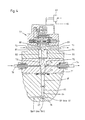
- This one-way suction valve 21 is preferably installed in the pump head 3 of the high-pressure injection pump 1 and has one. Equipment such as shown in Fig. 6.
- the one-way suction valve 21 consists of a valve sleeve 22, which is inserted into a receiving bore 23 of the pump head 3 and is locked in the installed position by a holding plate 24 screwed to the pump head 3.
- valve sleeve 22 has a connection thread 25 for connecting the inlet-side part of the feed line 20.
- the one-way suction valve-internal part of the feed line 20 is formed by a through hole 26, at the end of which a conical valve seat ring surface 27 connects, which leads into an enlarged fuel passage space 28 merges into which is connected a receiving bore 29 which extends through to the rear end for a valve body 30 which is axially displaceable therein.
- the valve body 30 has at its front end a conical valve cone 31 which cooperates with the valve seat ring surface 27, furthermore a fuel passage bore 32 drilled from the rear, designed as a blind hole, and transverse bores 33 which establish a continuous passage connection between the fuel passage bore 32 and the fuel passage space 28.
- the valve body 30 is acted upon by a compression spring 34 in the closing direction, that is to say from its rear side.
- the feed line 20 is formed within the one-way suction valve, i.e. through the bore 26, the fuel passage space 28, the passage transverse bores 33 and the fuel passage bore 32, and continues within the pump head 3 in the form of a bore 35, a transverse bore 36 and a bore 37, the latter of which opens into the pump pressure chamber 11 of the high-pressure injection pump 1.
- a return line 38 leading to the tank branches off directly from the pump pressure chamber (see FIG. 2) or from the delivery channel running between the latter and the pressure valve (see FIGS. 1 and 3).
- a combined passage and dynamic pressure shut-off valve 39 is switched on.
- An embodiment for this passage and dynamic pressure shut-off valve is shown in FIG. 6. It is preferably installed in the pump head 3 similarly to the one-way suction valve 21 and consists of a valve sleeve 40 which is inserted in a receiving bore 41 and is locked in the installation position on the pump head.
- valve sleeve 40 there is an inlet bore 42 which is in constant communication with the inlet-side part 38/1 of the return line, which is inside the pump head 3 through a bore branching off from the pump pressure chamber 11 or the delivery channel 12 and a transverse bore 43 and the rear free bore Part 44 of the receiving bore 41 for the valve sleeve 40 is formed.
- a conical valve seat ring surface 45 adjoins the valve sleeve, in turn an overflow chamber 46 and behind it a receiving bore 47 for a valve body 48 which can be axially displaced therein between two end positions.
- valve body 48 In its one end position, the valve body 48 shuts off the return line 38 with its valve seat 49 pressed against the valve seat ring surface 45, while on the other hand it releases the return line away from this end position.
- the valve body 48 can be pressed in the direction of the valve seat ring surface 45 by a rear part engaging on its rear part opposite the valve seat 49 and exerting a pressure force slightly below the feed pressure of the low-pressure feed pump 18.
- the overflow space 46 is in permanent passage connection via transverse bores 51 with an annular outflow space 52 located outside the valve sleeve, which is connected to the downstream part 38/2 of the return line 38.
- the valve body 48 has a continuous channel 53 with a throttle bore 54. Through this channel 53 and the throttle bore 54, fuel constantly flows from the inlet-side part 38/1 of the return line 38 into a dynamic pressure chamber 55 acting downstream of the throttle bore and from there into a dynamic pressure control line 56 connected to it (see also FIGS. 1 to 3).
- the dynamic pressure chamber 55 is formed by the part of the channel 53 which is behind the throttle bore 54 in terms of flow.
- the dynamic pressure control line 56 branches - as can be seen from FIGS. 1, 2 and 3 - into two parallel branches 56/1 and 56/2, which are separated from one another downstream of the branch point 57 (as shown in FIGS. 2 and 3) or again merged into a line part 58 via this (as shown in FIG. 1) open into the part 38/2 of the return line 38 which is downstream of the passage and dynamic pressure shut-off valve 39.
- a controlled one-way valve 59 and 60 is switched on in each of the two parallel branches 56/1, 56/2 of the dynamic pressure control line 56.
- the one-way valve 59 is hereinafter referred to as the "start of delivery one-way valve 59" and the one-way valve 60 as the "end of delivery one-way valve 60".
- the delivery start one-way valve 59 marks the start of delivery of the high-pressure injection pump 1 at the moment of its closing with the delivery end one-way valve 60 closed, while the delivery end one-way valve 60 marks the delivery end of the high-pressure injection pump 1 when it opens.
- both the start of delivery one-way valve 59 and the end of delivery one-way valve 60 are connected to their own actuating device 61 or 62 (FIGS. 1, 2 and 3) and this in turn is connected to a control device 63 which actuates the two one-way valves synchronously with the machine 59, 60 in the sense of operationally optimized values for the start and end of delivery of the high-pressure injection pump 1 controls.
- each of the two one-way valves 59, 60 has a valve body 65 which is received in an axially displaceable manner in a receiving bore 64.
- the latter has at its front end a preferably conical valve seat 66 which interacts with a correspondingly adapted conical valve seat ring surface 67.
- This valve seat ring surface 67 is formed by a conical widening on the inlet-side part of the respective parallel branch 56/1 or 56/2 of the dynamic pressure control line 56.
- the valve body 65 can be pressed by pressurization on its rear side opposite the valve cone in the closed position, in which the respective parallel branch 56/1 or 56/2 is shut off, and when the rear of the valve is relieved of pressure by the fuel pressure in at its front side having the valve seat 66 Pass position in which the respective parallel branch 56/1 or 56/2 is switched through, displaceable.
- valve body 65 of each of the two one-way valves 59 and 60 can directly z. B. by an electro-hydraulic servo valve or, as shown in Fig. 4, with the interposition of a pressure piston 68 from a pressure chamber, which is switched into a hydraulic high-pressure control circuit.
- the latter forms part of the actuating device.
- the introduction of a liquid high-pressure control medium to the pressure chamber 69 takes place via a high-pressure supply line 70, which continues as a bore within a control block 71 and can be released or blocked by the valve body 72 of a control valve 73.
- the liquid high-pressure control medium supplied to the pressure chamber 69 is deactivated via a high-pressure discharge line 74, which is likewise formed within the control block by bores and can be switched through or shut off by the valve body 75 of a further control valve 76.
- Each of the two valve bodies 72 and 75 has at its front end a valve cone which interacts with a correspondingly designed valve seat ring surface in the part of the high-pressure supply line 70 or high-pressure line 74 inside the control block.
- the opening and closing of the two control valves 73 and 76 is controlled by an electro-hydraulic servo valve 77 which is electronically activated by the control device. This servo valve 77 is of a known type and therefore need not be explained in detail here.
- FIG. 4 From the hydraulic auxiliary control circuit, only a feed line 78 for hydraulic control medium is shown in FIG. 4, which leads to an input of the servo valve 77 and a return line 79 branching off at an output of the servo valve 77.
- the hydraulic control medium can expediently be the fuel that is also used for the internal combustion engine.
- a pressure chamber 81 is connected to the one control output of the servo valve 77 via a control pressure line 80 at the rear of a pressure piston 82 acting in the closing direction on the valve body 72 of the control valve 73.
- a pressure chamber 84 is connected to a second control output of the servo valve 77 via a control pressure line 83, which pressure chamber 85 acts on the back of a pressure piston 85 acting in the closing direction on the valve body 75 of the control valve 76 is arranged.
- the servo valve is designed for the control of extremely short switching times in the millisecond range, so that the hydraulic auxiliary control circuit and the two control valves 73, 76 and the hydraulic high-pressure control circuit provide extremely precise pressure relief and relief of the pressure chamber 69 and thus extremely precise opening and closing of one Parallel branch 56/1 or 56/2 of the dynamic pressure control line 56 are guaranteed by the respective one-way valve 59 or 60.
- the servo valve 77 is connected to the electronic control device 63, which, as shown in FIGS. 1 to 3, is continuously signaled by a resolver 86 that the rotational angle position of the camshaft 9 is signaled via a signal line 87 and on the basis of these rotational angle messages and a special control program controls the respective servo valve 77. This control characteristic is explained further below in connection with the functional description of the high-pressure fuel injection device according to the invention.
- both one-way valves 59, 60 are each of identical design and are installed here in the pump head 3 of the high-pressure injection pump 1.
- Each of the two one-way control valves 59, 60 consists of a valve sleeve 90 installed in a receiving bore 88 of the pump head 3 and held in the installed position by a strip 89 fastened to the pump head.
- the valve body 65 is axially displaceably mounted between two end positions and in the closing direction from its rear side forth by a closing pressure spring 91.
- valve body 65 In its one end position the valve body 65 is pressed with a conical valve seat 92 against a correspondingly adapted valve seat ring surface 93 and in its other end position it is moved away from it.
- a fuel control chamber 94 connects to the valve seat ring surface 93 in front of the valve seat 92 of the valve body 65, which, via a transverse through bore 95 and a blind hole 96 drilled from the rear of the valve body 65, connects to the inlet-side part of a parallel branch 56/1 or 56/2 Dynamic pressure control line 56 is supplied with fuel.
- an annular fuel outlet space 97 adjoins the valve seat annular surface 93 and is connected via at least one transverse bore 98 to an annular fuel outflow chamber 99 surrounding the valve sleeve within the receiving bore 88. From the latter, the outlet-side part of the respective parallel branch 56/1 or 56/2 of the dynamic pressure control line 56 branches off, which flows into the return line 38 separately or together, as already mentioned above.
- an actuating rod 100 is arranged on the valve body 65 in one piece and coaxially therewith, which is guided in a receiving bore 101 of the valve sleeve 90.
- a plunger 102 forming part of the actuating device 61 or 62 engages on the front end face of the actuating rod 100 of the valve body 65. This is axially displaceably guided coaxially to the valve body in a receiving bore 103 and, under the action of a compression spring 104 acting on its rear side, is pressed against the peripheral control link 106 of a control sleeve 107 by a scanning roller 105 which is rotatably mounted in the region of its front end.
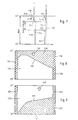
- the design of the control sleeve 107 and the control and confirmation members assigned to it can be seen in FIG. 5 and will be described below with reference to this. In FIG.
- Each of the two control sleeves 107 is arranged axially parallel to the pump piston 5 of the high-pressure injection pump 1 and is guided in a guide bore 108.
- the latter is formed in the illustrated embodiment as a through hole in a sleeve 109 inserted into the pump head 3.
- the control sleeve 107 is seated both against rotation and axially secured on a coaxially arranged actuating piston 110, which is guided in guide bores 111, 112 and acted on via the control sleeve 107 by a compression spring 113 countered in the pump head, under the action of which the lower end is pressed against a pressure plate 114 is.
- the pressure plate 114 itself is articulated to the pump piston 5 or its plunger 6 via a sleeve 115 formed integrally with it and synchronizes with the latter's stroke movements.
- Each peripheral surface 106 of a control sleeve 107 is designed as a control link for the actuation of a valve body 65.
- the two control links are different from one another, because with one control link 116, hereinafter referred to as "start of delivery control link 116", the valve body 65 of the start of delivery one-way valve 59 can be controlled, while with the other control link 117, hereinafter referred to as “end of delivery control link 117", the valve body 65 of the delivery end one-way valve 60 is controllable.
- 8 shows the handling of the start of funding.
- Control link 116 and from FIG. 9 the handling of the end of delivery control link 117 can be seen.
- the start of conveying control link 116 is composed of a raised control surface region 118, hatched in FIG. 8, and a recessed peripheral region 119, which is adjacent in the axial direction.
- the transition between these two peripheral regions 118, 119 of the control sleeve 107 is formed by an oblique control edge 120 which determines the start of delivery.
- the conveying end control link 117 is likewise composed of a raised, hatched area in FIG. 9 on the control sleeve 107 and an axially recessed peripheral area 122.
- the transition between the two peripheral regions 121 and 122 is formed by an oblique control edge 123 that determines the end of the conveying end.
- the circumferential regions 118 and 121 shown hatched in FIGS. 8 and 9 lie on the respective control sleeve 107 with the same diameter in each case.
- Both the start of delivery control link 116 and the end of delivery control link 117 can each be brought into a specific position with respect to the scanning roller 105 by rotating the associated control sleeve 107.
- each of the two control sleeves 107 is assigned a control rod 126 or 127, which is received in a receiving bore 128 of the pump head 3, which is perpendicular to the actuating piston 110, and with its toothing in a toothing 129 on Actuating piston 110 engages.
- Each of the two control rods 126 and 127 is axially reciprocated by an actuating element (not shown), which receives its setting commands from a controller or an electronic control unit 63, for rotating the connected control sleeve 107 and thus for adjusting the respective oblique control edge 120 or 123 slidable.
- the pump piston 5 of the high-pressure injection pump 1 is in the bottom dead center position, which is indicated in FIG. 7 by the transverse line labeled UT, then the one-way suction valve 21 is open; in addition, the one-way delivery valve 59 is in the open position because the scanning roller 105, as can be seen in FIG. 7, rests in the raised peripheral region 118 of the control link 116 and the valve cone 92 on the valve body 65 of the one-way delivery valve 59 has moved away from its valve seat ring surface 93 .
- the associated control sleeve 107 is also in its lowest dead center position, which is also marked in FIG. 7 by the transverse line labeled UT.
- a fuel flow from the low-pressure feed pump 18 is thereby promoted via the open one-way suction valve 21 to the pump pressure chamber 11 of the high-pressure injection pump and from there via the return line 38 and the now also open passage and dynamic pressure shut-off valve 39 back to the tank.
- the passage and dynamic pressure shut-off valve 39 is open because it is not acted upon by any dynamic pressure on its rear side and by the fuel feed pressure in the order of magnitude of 3 to 10 bar acting on its front side against the force of the closing pressure spring 50 with its valve seat 49 from the valve seat ring surface 45 is lifted off.
- the fuel present in the inlet-side part 38/1 of the return line 38 can also flow freely through the throttle bore 54 in the passage and dynamic pressure shut-off valve and pass through the dynamic pressure control line 56 and its now open parallel branch 56/1 into the return line 38 and flow back to the tank via this . From this it can be seen that at this stage the high-pressure injection pump 1 is completely flowed through by fuel.
- the one-way suction valve 21 initially closes because its valve cone 31 is pressed against the valve seat ring surface 27 by the pressure build-up in the pump pressure chamber 11, which propagates via the conduit paths 37, 36 and 35.
- the passage and back pressure shut-off valve 39 is still open at this stage of the upward stroke of the pump plunger 5.
- the conveying end one-way valve 60 has been in the closed position up to this stage, as already indicated earlier, because the associated scanning roller 105, as can be seen in FIG. 7, is in the recessed area 122 of the control link 117 on the control sleeve belonging to this one-way valve 60 107 moves and thereby the valve cone 92 is pressed by its valve body onto the associated valve seat ring surface 93.
- the pressure build-up within the pump pressure chamber 11 of the high-pressure injection pump 1 is controlled in a conventional manner by the contour of the control cam 8, the fuel delivered being conveyed via the pressure valve 13 arranged on the pump outlet side and the connecting line 14 to the injection valve 15 and via the latter into the connected combustion chamber is injected.
- the start of delivery one-way valve 59 remains closed during the entire subsequent delivery stroke of the pump piston 5, because the associated scanning roller 105 moves in the recessed partial region 119 of the control link 116 on the associated control sleeve 107.
- the delivery end of the high-pressure injection pump 1 occurs when the control sleeve 107 assigned to it, with its oblique control edge 123, moves the scanning roller 105 and the latter then comes into contact with the raised part 121 of the control link 117, as a result of which the valve cone 92 on the valve body 65 of the delivery end One-way valve 60 is moved away from the associated valve seat ring surface 93 and held in the open position.
- the pump piston 5 delivers fuel from the pressure chamber 11 essentially only via the return line 38 and the open passage and dynamic pressure shut-off valve 39 back into the tank.
- the delivery end one-way valve 60 is subsequently closed again because the associated scanning roller 105 again passes through the inclined control edge 123 into the recessed area 122 of the associated control sleeve 107, as a result of which the valve body 65 of the delivery end one-way valve 60 is in again its closed position is traceable and then rests with its valve seat 92 on the associated valve seat ring surface 93. Then the parallel branch 56/2 of the dynamic pressure control line 56 is shut off again, so that no fuel can flow back to the tank via this line path.
- the scanning roller 105 assigned to the start of delivery one-way valve 59 still moves for a certain period of time, namely until the oblique control edge 120 is reached, in the recessed part 119 of the associated control sleeve 107, so that the start of delivery one-way valve 59 is closed and thus also no fuel can flow back to the tank via the parallel branch 56/1 of the dynamic pressure control line 56.
- the change and the optimal setting of the control times "start of delivery” and “end of delivery” of the high-pressure injection pump takes place via corresponding commands which the electronic control device 63 receives via channels 130 from a command status or directly depending on operating values of the sensors detecting the internal combustion engine.
- the high-pressure fuel injection device offers the possibility of any change in these control times while the high-pressure injection pump is running.
- extremely quickly and effectively changing operating states of the internal combustion engine or changing, in particular deteriorating operating values, such as deteriorating fuel quality or certain conditions of the charge air can be taken into account by appropriately adjusting the start and end of delivery of the high-pressure injection pump.
- the high-pressure injection pump has no sloping control edges on the pump plunger and no suction holes in the wall of the pump cylinder, extremely high volumetric efficiencies can be achieved, even at the highest pressures.
Landscapes
- Engineering & Computer Science (AREA)
- Chemical & Material Sciences (AREA)
- Combustion & Propulsion (AREA)
- Mechanical Engineering (AREA)
- General Engineering & Computer Science (AREA)
- Fuel-Injection Apparatus (AREA)
Claims (8)
Applications Claiming Priority (2)
| Application Number | Priority Date | Filing Date | Title |
|---|---|---|---|
| DE3504265 | 1985-02-08 | ||
| DE19853504265 DE3504265A1 (de) | 1985-02-08 | 1985-02-08 | Kraftstoffhochdruck-einspritzvorrichtung an brennkraftmaschinen |
Publications (2)
| Publication Number | Publication Date |
|---|---|
| EP0194431A1 EP0194431A1 (fr) | 1986-09-17 |
| EP0194431B1 true EP0194431B1 (fr) | 1988-04-27 |
Family
ID=6261973
Family Applications (1)
| Application Number | Title | Priority Date | Filing Date |
|---|---|---|---|
| EP86101067A Expired EP0194431B1 (fr) | 1985-02-08 | 1986-01-27 | Dispositif d'injection de carburant à haute pression pour moteur à combustion interne |
Country Status (4)
| Country | Link |
|---|---|
| EP (1) | EP0194431B1 (fr) |
| JP (1) | JPH0665873B2 (fr) |
| DE (2) | DE3504265A1 (fr) |
| FI (1) | FI79889C (fr) |
Families Citing this family (3)
| Publication number | Priority date | Publication date | Assignee | Title |
|---|---|---|---|---|
| DE19926308A1 (de) * | 1999-06-09 | 2000-12-21 | Bosch Gmbh Robert | Pumpenanordnung für Kraftstoff |
| DE102004050023A1 (de) * | 2004-10-13 | 2006-04-27 | L'orange Gmbh | Einrichtung zur dosierten Einspritzung eines Reduktionsmittels in den Abgastrakt einer Brennkraftmaschine |
| DE112020001266T5 (de) * | 2019-04-18 | 2021-11-25 | Hitachi Astemo, Ltd. | Hochdruckkraftstoffpumpe |
Citations (1)
| Publication number | Priority date | Publication date | Assignee | Title |
|---|---|---|---|---|
| DE2742466A1 (de) * | 1977-09-21 | 1979-03-29 | Daimler Benz Ag | Pumpe-duese fuer luftverdichtende einspritzbrennkraftmaschinen |
Family Cites Families (8)
| Publication number | Priority date | Publication date | Assignee | Title |
|---|---|---|---|---|
| DE1917927A1 (de) * | 1969-04-09 | 1970-10-29 | Bosch Gmbh Robert | Kraftstoffeinspritzpumpe fuer Brennkraftmaschinen |
| DD113260A1 (fr) * | 1974-07-08 | 1975-05-20 | Karl Marx Stadt Automobilbau | |
| DE2529933C2 (de) * | 1975-07-04 | 1984-07-19 | M.A.N. Maschinenfabrik Augsburg-Nürnberg AG, 8900 Augsburg | Brennstoffeinspritzvorrichtung für Brennkraftmaschinen |
| JPS56500971A (fr) * | 1979-08-08 | 1981-07-16 | ||
| DE3039967A1 (de) * | 1980-10-23 | 1982-06-03 | Robert Bosch Gmbh, 7000 Stuttgart | Kraftstoffeinspritzanlage |
| DE3147467C1 (de) * | 1981-12-01 | 1983-04-21 | Daimler-Benz Ag, 7000 Stuttgart | Einspritzanlage fuer Brennkraftmaschinen |
| DE3211877A1 (de) * | 1982-03-31 | 1983-10-06 | Bosch Gmbh Robert | Kraftstoffeinspritzpumpe |
| IT1150843B (it) * | 1982-04-19 | 1986-12-17 | Spica Spa | Regolatore di mandata per pompa di iniezione del combustibile |
-
1985
- 1985-02-08 DE DE19853504265 patent/DE3504265A1/de not_active Ceased
- 1985-12-13 FI FI854943A patent/FI79889C/fi not_active IP Right Cessation
-
1986
- 1986-01-27 EP EP86101067A patent/EP0194431B1/fr not_active Expired
- 1986-01-27 DE DE8686101067T patent/DE3660159D1/de not_active Expired
- 1986-02-07 JP JP61024256A patent/JPH0665873B2/ja not_active Expired - Lifetime
Patent Citations (1)
| Publication number | Priority date | Publication date | Assignee | Title |
|---|---|---|---|---|
| DE2742466A1 (de) * | 1977-09-21 | 1979-03-29 | Daimler Benz Ag | Pumpe-duese fuer luftverdichtende einspritzbrennkraftmaschinen |
Also Published As
| Publication number | Publication date |
|---|---|
| DE3660159D1 (en) | 1988-06-01 |
| FI854943A7 (fi) | 1986-08-09 |
| JPS61187572A (ja) | 1986-08-21 |
| FI79889B (fi) | 1989-11-30 |
| DE3504265A1 (de) | 1986-08-14 |
| FI854943A0 (fi) | 1985-12-13 |
| FI79889C (fi) | 1990-03-12 |
| JPH0665873B2 (ja) | 1994-08-24 |
| EP0194431A1 (fr) | 1986-09-17 |
Similar Documents
| Publication | Publication Date | Title |
|---|---|---|
| DE60034417T2 (de) | Kraftstoffeinspritzventil für Hubkolbenbrennkraftmaschine | |
| DE60126380T2 (de) | Kraftstoffeinspritzventil | |
| DE19616812B4 (de) | Kraftstoffeinspritzvorrichtung | |
| DE69230213T2 (de) | Elektromagnetisches Kraftstoffeinspritzventil | |
| DE60015218T2 (de) | Brennstoffeinspritzventil | |
| DE2447741C2 (fr) | ||
| DE3541938C2 (de) | Magnet-Überströmventil | |
| DE2809762C2 (fr) | ||
| DE3824467C2 (fr) | ||
| EP0959243A1 (fr) | Soupape de commande pour injecteur à combustible | |
| DE60034722T2 (de) | Kraftstoffeinspritzanordnung | |
| EP0615064B1 (fr) | Système de commande d'une soupape d'injection d'un moteur à combustion interne | |
| DE102007000095B4 (de) | Kraftstoffeinspritzelement | |
| DE60015037T2 (de) | Brennstoffeinspritzventil | |
| DE2740879C2 (fr) | ||
| DE19612721C2 (de) | Speichereinspritzsystem mit Voreinspritzung für eine Brennkraftmaschine | |
| DE69006194T2 (de) | Kraftstoffpumpenvorrichtung. | |
| CH671809A5 (fr) | ||
| DE10139055A1 (de) | Verfahren, Computerprogramm, Steuer- und/oder Regelgerät sowie Kraftstoffsystem für eine Brennkraftmaschine | |
| EP0090296B1 (fr) | Buse d'injection à aiguille | |
| EP0194431B1 (fr) | Dispositif d'injection de carburant à haute pression pour moteur à combustion interne | |
| DE3248086C2 (de) | Kraftstoffeinspritzpumpe für Brennkraftmaschinen, insbesondere für Dieselmotoren | |
| DE2037449B2 (de) | Kraftstoffeinspritzpumpe für Brennkraftmaschinen | |
| DE1601985B2 (fr) | ||
| DE3236828A1 (de) | Brennstoffeinspritzvorrichtung |
Legal Events
| Date | Code | Title | Description |
|---|---|---|---|
| PUAI | Public reference made under article 153(3) epc to a published international application that has entered the european phase |
Free format text: ORIGINAL CODE: 0009012 |
|
| AK | Designated contracting states |
Kind code of ref document: A1 Designated state(s): CH DE FR LI NL |
|
| 17P | Request for examination filed |
Effective date: 19860822 |
|
| 17Q | First examination report despatched |
Effective date: 19870130 |
|
| GRAA | (expected) grant |
Free format text: ORIGINAL CODE: 0009210 |
|
| AK | Designated contracting states |
Kind code of ref document: B1 Designated state(s): CH DE FR LI NL |
|
| REF | Corresponds to: |
Ref document number: 3660159 Country of ref document: DE Date of ref document: 19880601 |
|
| ET | Fr: translation filed | ||
| PLBE | No opposition filed within time limit |
Free format text: ORIGINAL CODE: 0009261 |
|
| STAA | Information on the status of an ep patent application or granted ep patent |
Free format text: STATUS: NO OPPOSITION FILED WITHIN TIME LIMIT |
|
| 26N | No opposition filed | ||
| PGFP | Annual fee paid to national office [announced via postgrant information from national office to epo] |
Ref country code: CH Payment date: 20001214 Year of fee payment: 16 |
|
| PGFP | Annual fee paid to national office [announced via postgrant information from national office to epo] |
Ref country code: NL Payment date: 20001222 Year of fee payment: 16 |
|
| PGFP | Annual fee paid to national office [announced via postgrant information from national office to epo] |
Ref country code: DE Payment date: 20010102 Year of fee payment: 16 |
|
| PGFP | Annual fee paid to national office [announced via postgrant information from national office to epo] |
Ref country code: FR Payment date: 20010103 Year of fee payment: 16 |
|
| PG25 | Lapsed in a contracting state [announced via postgrant information from national office to epo] |
Ref country code: CH Free format text: LAPSE BECAUSE OF NON-PAYMENT OF DUE FEES Effective date: 20020131 Ref country code: LI Free format text: LAPSE BECAUSE OF NON-PAYMENT OF DUE FEES Effective date: 20020131 |
|
| PG25 | Lapsed in a contracting state [announced via postgrant information from national office to epo] |
Ref country code: DE Free format text: LAPSE BECAUSE OF NON-PAYMENT OF DUE FEES Effective date: 20020801 Ref country code: NL Free format text: LAPSE BECAUSE OF NON-PAYMENT OF DUE FEES Effective date: 20020801 |
|
| REG | Reference to a national code |
Ref country code: CH Ref legal event code: PL |
|
| PG25 | Lapsed in a contracting state [announced via postgrant information from national office to epo] |
Ref country code: FR Free format text: LAPSE BECAUSE OF NON-PAYMENT OF DUE FEES Effective date: 20020930 |
|
| NLV4 | Nl: lapsed or anulled due to non-payment of the annual fee |
Effective date: 20020801 |
|
| REG | Reference to a national code |
Ref country code: FR Ref legal event code: ST |