EP0194504A2 - Corps composite et son procédé de fabrication - Google Patents
Corps composite et son procédé de fabrication Download PDFInfo
- Publication number
- EP0194504A2 EP0194504A2 EP86102444A EP86102444A EP0194504A2 EP 0194504 A2 EP0194504 A2 EP 0194504A2 EP 86102444 A EP86102444 A EP 86102444A EP 86102444 A EP86102444 A EP 86102444A EP 0194504 A2 EP0194504 A2 EP 0194504A2
- Authority
- EP
- European Patent Office
- Prior art keywords
- metal
- ceramic
- bonding portion
- composite
- ceramic body
- Prior art date
- Legal status (The legal status is an assumption and is not a legal conclusion. Google has not performed a legal analysis and makes no representation as to the accuracy of the status listed.)
- Granted
Links
Images
Classifications
-
- B—PERFORMING OPERATIONS; TRANSPORTING
- B22—CASTING; POWDER METALLURGY
- B22F—WORKING METALLIC POWDER; MANUFACTURE OF ARTICLES FROM METALLIC POWDER; MAKING METALLIC POWDER; APPARATUS OR DEVICES SPECIALLY ADAPTED FOR METALLIC POWDER
- B22F7/00—Manufacture of composite layers, workpieces, or articles, comprising metallic powder, by sintering the powder, with or without compacting wherein at least one part is obtained by sintering or compression
- B22F7/06—Manufacture of composite layers, workpieces, or articles, comprising metallic powder, by sintering the powder, with or without compacting wherein at least one part is obtained by sintering or compression of composite workpieces or articles from parts, e.g. to form tipped tools
-
- B—PERFORMING OPERATIONS; TRANSPORTING
- B22—CASTING; POWDER METALLURGY
- B22F—WORKING METALLIC POWDER; MANUFACTURE OF ARTICLES FROM METALLIC POWDER; MAKING METALLIC POWDER; APPARATUS OR DEVICES SPECIALLY ADAPTED FOR METALLIC POWDER
- B22F3/00—Manufacture of workpieces or articles from metallic powder characterised by the manner of compacting or sintering; Apparatus specially adapted therefor ; Presses and furnaces
- B22F3/10—Sintering only
-
- C—CHEMISTRY; METALLURGY
- C04—CEMENTS; CONCRETE; ARTIFICIAL STONE; CERAMICS; REFRACTORIES
- C04B—LIME, MAGNESIA; SLAG; CEMENTS; COMPOSITIONS THEREOF, e.g. MORTARS, CONCRETE OR LIKE BUILDING MATERIALS; ARTIFICIAL STONE; CERAMICS; REFRACTORIES; TREATMENT OF NATURAL STONE
- C04B37/00—Joining burned ceramic articles with other burned ceramic articles or other articles by heating
- C04B37/02—Joining burned ceramic articles with other burned ceramic articles or other articles by heating with metallic articles
-
- Y—GENERAL TAGGING OF NEW TECHNOLOGICAL DEVELOPMENTS; GENERAL TAGGING OF CROSS-SECTIONAL TECHNOLOGIES SPANNING OVER SEVERAL SECTIONS OF THE IPC; TECHNICAL SUBJECTS COVERED BY FORMER USPC CROSS-REFERENCE ART COLLECTIONS [XRACs] AND DIGESTS
- Y10—TECHNICAL SUBJECTS COVERED BY FORMER USPC
- Y10T—TECHNICAL SUBJECTS COVERED BY FORMER US CLASSIFICATION
- Y10T428/00—Stock material or miscellaneous articles
- Y10T428/12—All metal or with adjacent metals
- Y10T428/12014—All metal or with adjacent metals having metal particles
Definitions
- the present invention relates to a composite body obtained by combining and bonding a sintered metal body and a sintered ceramic body and a method of manufacturing the same.
- Ishida et al. describe a bonding method in Japanese Patent Disclosure No. 59-205406.
- a metal ring-shaped body is obtained after pre-forming a metal powder.
- a sintered ceramic body is fitted in the metal body and the assembly is sintered.
- the sintered metal body contracts and compresses the ceramic body.
- a bonding portion is formed in a ceramic body.
- a sintered metal body locks with the bonding portion of the ceramic body provided, if necessary, with an infiltrator, and thus, physically bonds the ceramic and metal bodies together.
- a bonding portion is formed in a sintered ceramic body.
- a sintered metal body is fitted to the bonding portion or an infiltrator is filled in a space which the bonds portion and the sintered metal body, which bonds the ceramic and metal bodies.
- the bonding portion must be able to withstand forces applied to the composite body. Therefore, the bonding portion can be an annular groove or have a step-like profile in a cross-section.
- Different combinations of ceramic and metal bodies include:
- Composite bodies consisting of ceramic and metal bodies having different thermal expansion coefficients are effectively manufactured by sintering the bodies in a heated atmosphere. When such a difference in thermal expansion coefficient is present the ceramic and metal bodies are bonded more firmly.
- Composite bodies of combinations (c) and (d) are also suitable for manufacture in a heated atmosphere.
- the reason for this can be surmised as follows.
- the matrix body regulates thermal expansion of the metal body, a thermal expansion reaction is generated in the metal body. This reaction force serves to securely bond the ceramic and metal bodies, thereby providing an integral composite body.
- the materials can be selected as described above or a ceramic powder such as glass can be mixed with a metal powder.
- a composite body of the present invention is manufactured in the following manner.
- step (d) if the metal body is infiltrated with an infiltrator such as copper, the strength of the metal body is increased. In addition, the infiltrator bonds with the ceramic body, thereby improving the bonding strength between the two sintered bodies.
- an infiltrator such as copper
- step (b) described above one of metal bodies M2 to M4 (excluding metal body M1) is combined with a ceramic body. A space is formed enclosed by the bonding portion of the ceramic body and the metal body, step (c) is omitted, and step (d) follows directly. At the same time, an infiltrator such as copper is infiltrated into the bonding portion, thereby manufacturing a composite body. In the obtained composite body, the ceramic and metal bodies are securely bonded with each other and with the infiltrator infiltrated into the bonding portion.
- sintering step (d) is performed without performing step (c). During or after sintering step (d), the above-mentioned infiltration step can be performed.
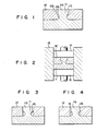
- Ceramic body 11 has rod-like portion 11 a at the center of a plate.
- Annular groove 11 b is formed in a part of the outer circumferential surface of rod-like portion 11a, and . serves as a bonding portion.
- Metal body 12 has hole 12a for fitting over portion 11a of ceramic body 11.
- Projection 1 2b locks with annular groove 11 b after the composite body is compressed.
- ceramic body 11 is placed inside die 13.
- a metal powder filled on ceramic body 1 1 is pressed by upper and lower punches 14 and 15 to produce green compact metal body 12'. With this method, the metal powder flows and enters groove 11 b of ceramic body 1 1.
- Formed metal body 12' is sintered to provide the composite body shown in Fig. 2.
- a metal powder is pressed into green compact metal body 12' with pores. After presintering, metal body 12' is combined with ceramic body 11. Presintered metal body 12' is pressed to partially crease it, such that the creased portion extends into groove 11 b of ceramic body 11. Metal and ceramic bodies 12' and 11 are sintered to obtain the composite body shown in Fig. 3. In the sintering step or in a later step, the infiltration step can also be performed.
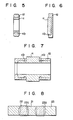
- Presintered metal body 12' is combined with ceramic body 1 1 .
- bodies 12' and 11 are combined, a space is formed between groove 11 a of body 11 and body 12'.
- the assembly is sintered without pressing metal body 12', and at the same time or in a later step, an infiltrator such as copper is infiltrated into the bonding portion.
- an infiltrator such as copper is infiltrated into the bonding portion.
- the two bodies are bonded at the bonding portion with infiltrator 16.
- the composite bodies shown in these figures have different shapes or combinations of ceramic and metal bodies and bonding portions. These shapes and combinations are selected in accordance with the possible forces expected to be applied uses of the composite bodies and possible applications thereof.
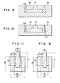
- Ceramic body 21 is inserted in a central hole of metal matrix body 23 with a predetermined gap left therebetween. Annular presintered metal body 22, indicated by the dotted line, is fitted in the gap. Metal body 22 is pressed so that it locks with both bonding portion 23a of the matrix body and with bonding portion 21 a of ceramic body 21. The assembly is sintered to obtain the composite body.
- Metal matrix body 33 has a recess having a tapered sectional shape.
- Ceramic body 31 has a shape obtained by placing a small disk at the center of a large disk. Ceramic body 31 is placed in the recess of matrix body 33 with a predetermined gap left therebetween. Annular presintered metal body 32, indicated by the dotted line, is fitted in the gap. The space enclosed by metal body 32 and matrix body 33 is bonding portion 33a of matrix body 33. Metal body 32 is pressed to extend into bonding portion 33a and lock therewith. Thereafter, the assembly is sintered to complete the composite body..
- Ceramic body 31 and metal body 32 of the same shapes as those in Fig. 9 are fitted in a recess of matrix body 33.
- Infiltrator 34 is infiltrated in bonding portion 33a of the matrix body through metal body 32 during or after sintering, thereby completing the composite body.
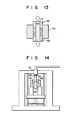
- the respective samples were manufactured in the following manner. As shown in Fig.13, ceramic body 41 was placed in die 44. After filling the metal powder on lower punch 45 in a space defined by matrix body 43 and ceramic body 41, pressing was performed by upper punch 46 at a pressure of 6 ton/cm 2 . The assembly was sintered at 1,200°C to obtain metal body 42, which- was contracted by 1.1 %. After forming a composite body by combining ceramic body 41 and metal body 42, it was pressed into matrix body 43 by a press machine to obtain the sample shown in Figs. 11 and 12. In some samples, a copper mass was placed on sintered metal body 42 and heated to allow infiftration.
- the bonding strength was 7.8 to 8.3 kg/mm 2. This bonding strength is about 15% higher than Control samples. In the samples of the Example in which copper was infiltrated, the bonding strength was 12.6 to 14.8 kg/mm 2. This bonding strength is about 65% higher than the samples in which copper was not infiltrated.
Landscapes
- Chemical & Material Sciences (AREA)
- Engineering & Computer Science (AREA)
- Manufacturing & Machinery (AREA)
- Materials Engineering (AREA)
- Mechanical Engineering (AREA)
- Composite Materials (AREA)
- Ceramic Engineering (AREA)
- Structural Engineering (AREA)
- Organic Chemistry (AREA)
- Ceramic Products (AREA)
- Powder Metallurgy (AREA)
Applications Claiming Priority (2)
| Application Number | Priority Date | Filing Date | Title |
|---|---|---|---|
| JP60036975A JPS61197476A (ja) | 1985-02-26 | 1985-02-26 | 複合体およびその製造方法 |
| JP36975/85 | 1985-02-26 |
Publications (3)
| Publication Number | Publication Date |
|---|---|
| EP0194504A2 true EP0194504A2 (fr) | 1986-09-17 |
| EP0194504A3 EP0194504A3 (en) | 1987-02-04 |
| EP0194504B1 EP0194504B1 (fr) | 1990-01-24 |
Family
ID=12484753
Family Applications (1)
| Application Number | Title | Priority Date | Filing Date |
|---|---|---|---|
| EP86102444A Expired - Lifetime EP0194504B1 (fr) | 1985-02-26 | 1986-02-25 | Corps composite et son procédé de fabrication |
Country Status (5)
| Country | Link |
|---|---|
| US (1) | US4857411A (fr) |
| EP (1) | EP0194504B1 (fr) |
| JP (1) | JPS61197476A (fr) |
| KR (1) | KR890003858B1 (fr) |
| DE (1) | DE3668430D1 (fr) |
Cited By (6)
| Publication number | Priority date | Publication date | Assignee | Title |
|---|---|---|---|---|
| EP0368791A1 (fr) * | 1988-11-10 | 1990-05-16 | Lanxide Technology Company, Lp. | Méthode pour lier des matériaux à la surface, par utilisation d'un composite avec une matrice en métal, et les produits obtenus |
| GB2248851A (en) * | 1990-10-15 | 1992-04-22 | Lilliwyte Sa | Making a sintered composite body |
| RU2120352C1 (ru) * | 1997-11-26 | 1998-10-20 | Республиканский инженерно-технический центр порошковой металлургии с НИИ. проблем порошковой технологии и покрытий и опытным производством | Способ соединения деталей из порошковых материалов |
| RU2238822C2 (ru) * | 2002-12-24 | 2004-10-27 | Общество с ограниченной ответственностью "Металлургическая компания "Борец" | Способ изготовления спеченных изделий (варианты) |
| RU2245761C2 (ru) * | 2003-04-29 | 2005-02-10 | Общество с ограниченной ответственностью "Металлургическая компания "Борец" | Способ изготовления спеченных изделий |
| US8141225B2 (en) | 2007-02-01 | 2012-03-27 | Rolls-Royce, Plc | Method of manufacturing a component by consolidating powder material |
Families Citing this family (14)
| Publication number | Priority date | Publication date | Assignee | Title |
|---|---|---|---|---|
| JP2506330B2 (ja) * | 1986-01-24 | 1996-06-12 | 日本発条株式会社 | 金属とセラミツク類からなる複合材の製造方法 |
| DE3914333A1 (de) * | 1989-04-29 | 1990-10-31 | Hoechst Ceram Tec Ag | Pumpenkolben fuer axialkolbenpumpen |
| SE9001409D0 (sv) * | 1990-04-20 | 1990-04-20 | Sandvik Ab | Metod foer framstaellning av haardmetallkropp foer bergborrverktyg och slitdelar |
| JPH05345683A (ja) * | 1992-06-16 | 1993-12-27 | Ngk Insulators Ltd | セラミックスと金属との複合体 |
| US5445688A (en) * | 1994-03-03 | 1995-08-29 | General Electric Company | Method of making alloy standards having controlled inclusions |
| US6416846B2 (en) | 1996-05-17 | 2002-07-09 | Kabushiki Kaisha Toshiba | Composite material and manufacturing method thereof |
| DE10007414B4 (de) * | 2000-02-18 | 2006-07-06 | eupec Europäische Gesellschaft für Leistungshalbleiter mbH & Co. KG | Verfahren zur Durchkontaktierung eines Substrats für Leistungshalbleitermodule durch Lot und mit dem Verfahren hergestelltes Substrat |
| US6378755B1 (en) * | 2000-11-08 | 2002-04-30 | General Electric Company | Joined structure utilizing a ceramic foam bonding element, and its fabrication |
| US6838046B2 (en) * | 2001-05-14 | 2005-01-04 | Honeywell International Inc. | Sintering process and tools for use in metal injection molding of large parts |
| US6770114B2 (en) | 2001-12-19 | 2004-08-03 | Honeywell International Inc. | Densified sintered powder and method |
| US20060275607A1 (en) * | 2005-06-06 | 2006-12-07 | Semih Demir | Composite assemblies including powdered metal components |
| US7857193B2 (en) * | 2005-11-23 | 2010-12-28 | Babcock & Wilcox Technical Services Y-12, Llc | Method of forming and assembly of parts |
| JP6163838B2 (ja) * | 2013-04-05 | 2017-07-19 | 富士電機株式会社 | 加圧加熱接合構造及び加圧加熱接合方法 |
| JP6213198B2 (ja) * | 2013-12-06 | 2017-10-18 | 株式会社デンソー | 接合体の製造方法 |
Family Cites Families (18)
| Publication number | Priority date | Publication date | Assignee | Title |
|---|---|---|---|---|
| FR895819A (fr) * | 1942-03-26 | 1945-02-05 | Procédé de fabrication de corps frittés | |
| US3839779A (en) * | 1973-09-07 | 1974-10-08 | Atomic Energy Commission | Ceramic brazing method |
| US4137106A (en) * | 1976-07-26 | 1979-01-30 | Sumitomo Electric Industries, Ltd. | Super hard metal roll assembly and production thereof |
| GB1588920A (en) * | 1977-08-11 | 1981-04-29 | British Ceramic Res Ass | Joining of metals to ceramics |
| JPS5830361B2 (ja) * | 1979-02-26 | 1983-06-29 | 日本ピストンリング株式会社 | 内燃機関用耐摩耗性部材の製造方法 |
| DE3023108C2 (de) * | 1979-07-02 | 1986-04-24 | Aupac K.K., Tokio/Tokyo | Verfahren zum Herstellen eines Kommutators |
| JPS56165582A (en) * | 1980-05-26 | 1981-12-19 | Agency Of Ind Science & Technol | Method for joining of porous body and ingot body |
| US4350528A (en) * | 1980-06-12 | 1982-09-21 | Trw Inc. | Method for diffusion bonding workpieces and article fabricated by same |
| SE423562B (sv) * | 1980-11-13 | 1982-05-10 | Cerac Inst Sa | Forfarande for framstellning av en stalkropp innefattande insatser av hart material |
| DK38981A (da) * | 1981-01-29 | 1982-07-30 | Danfoss As | Metode til forbinding af reaktionssintrede emner af siliciumkkarbid med emner af jern eller metal samt ionisationselektrode fremstillet ifoelge motoden |
| US4453605A (en) * | 1981-04-30 | 1984-06-12 | Nl Industries, Inc. | Drill bit and method of metallurgical and mechanical holding of cutters in a drill bit |
| DE3132141C1 (de) * | 1981-08-14 | 1982-12-16 | MTU Motoren- und Turbinen-Union München GmbH, 8000 München | Verfahren zum Herstellen von Sinterteilen grosser Gennauigkeit |
| JPS5841775A (ja) * | 1981-09-07 | 1983-03-11 | 大同特殊鋼株式会社 | セラミツクス−金属複合体の製造方法 |
| GB2117799B (en) * | 1982-03-05 | 1985-11-27 | Rolls Royce | Composite ceramic metal components |
| DE3372267D1 (en) * | 1982-03-31 | 1987-08-06 | De Beers Ind Diamond | Abrasive bodies |
| JPS59205406A (ja) * | 1983-05-07 | 1984-11-21 | Ngk Spark Plug Co Ltd | セラミツクスと金属との接合体の製造法 |
| US4598025A (en) * | 1985-07-19 | 1986-07-01 | Gte Products Corporation | Ductile composite interlayer for joining by brazing |
| US4698271A (en) * | 1985-12-30 | 1987-10-06 | The United States Of America As Represented By The Department Of Energy | Copper-silver-titanium filler metal for direct brazing of structural ceramics |
-
1985
- 1985-02-26 JP JP60036975A patent/JPS61197476A/ja active Pending
-
1986
- 1986-02-19 KR KR1019860001143A patent/KR890003858B1/ko not_active Expired
- 1986-02-25 EP EP86102444A patent/EP0194504B1/fr not_active Expired - Lifetime
- 1986-02-25 DE DE8686102444T patent/DE3668430D1/de not_active Expired - Lifetime
-
1987
- 1987-11-27 US US07/125,783 patent/US4857411A/en not_active Expired - Fee Related
Cited By (9)
| Publication number | Priority date | Publication date | Assignee | Title |
|---|---|---|---|---|
| EP0368791A1 (fr) * | 1988-11-10 | 1990-05-16 | Lanxide Technology Company, Lp. | Méthode pour lier des matériaux à la surface, par utilisation d'un composite avec une matrice en métal, et les produits obtenus |
| AU624416B2 (en) * | 1988-11-10 | 1992-06-11 | Lanxide Corporation | A method of surface bonding materials together by use of a metal matrix composite, and products produced thereby |
| CN1065849C (zh) * | 1988-11-10 | 2001-05-16 | 兰克西敦技术公司 | 用金属基质复合体表面粘结材料的方法 |
| GB2248851A (en) * | 1990-10-15 | 1992-04-22 | Lilliwyte Sa | Making a sintered composite body |
| GB2248851B (en) * | 1990-10-15 | 1994-04-27 | Lilliwyte Sa | Method of making composite sintered artifact |
| RU2120352C1 (ru) * | 1997-11-26 | 1998-10-20 | Республиканский инженерно-технический центр порошковой металлургии с НИИ. проблем порошковой технологии и покрытий и опытным производством | Способ соединения деталей из порошковых материалов |
| RU2238822C2 (ru) * | 2002-12-24 | 2004-10-27 | Общество с ограниченной ответственностью "Металлургическая компания "Борец" | Способ изготовления спеченных изделий (варианты) |
| RU2245761C2 (ru) * | 2003-04-29 | 2005-02-10 | Общество с ограниченной ответственностью "Металлургическая компания "Борец" | Способ изготовления спеченных изделий |
| US8141225B2 (en) | 2007-02-01 | 2012-03-27 | Rolls-Royce, Plc | Method of manufacturing a component by consolidating powder material |
Also Published As
| Publication number | Publication date |
|---|---|
| JPS61197476A (ja) | 1986-09-01 |
| US4857411A (en) | 1989-08-15 |
| DE3668430D1 (de) | 1990-03-01 |
| EP0194504B1 (fr) | 1990-01-24 |
| KR890003858B1 (ko) | 1989-10-05 |
| KR860006419A (ko) | 1986-09-11 |
| EP0194504A3 (en) | 1987-02-04 |
Similar Documents
| Publication | Publication Date | Title |
|---|---|---|
| US4857411A (en) | Composite body and method of manufacturing the same | |
| EP0786299A1 (fr) | Procédé de fabrication d'un anneau de synchronisation fritté | |
| EP0087881A1 (fr) | Procédé de liaison de cuivre ou alliage de cuivre-chrome avec des céramiques et produits liés en céramique et cuivre ou alliage de cuivre-chrome | |
| US5886269A (en) | Substrate and heat sink for a semiconductor and method of manufacturing the same | |
| JP2506330B2 (ja) | 金属とセラミツク類からなる複合材の製造方法 | |
| WO2016021362A1 (fr) | Procédé permettant la fabrication de corps fritté composite | |
| JP7575864B2 (ja) | 電極埋設部材の製造方法 | |
| JP7792254B2 (ja) | 接合体、その製造方法、および電極埋設部材 | |
| JPH1171186A (ja) | セラミックと金属との結合構造およびその結合方法 | |
| EP1043754B1 (fr) | Scellement pour lampes utilisant un matériau à gradient fonctionnel | |
| JP7780287B2 (ja) | 接合体、その製造方法、および電極埋設部材 | |
| JP3346372B2 (ja) | ランプ用傾斜機能材料製封止部材 | |
| JP3295838B2 (ja) | マグネトロン用エンドハットおよびその製造方法 | |
| JP7773879B2 (ja) | 接合体、その製造方法、および電極埋設部材 | |
| JP2000034173A (ja) | 複合焼結体の製造方法 | |
| JPH05156319A (ja) | 径方向に傾斜機能層を形成した円筒状または円柱状セラ ミックスー金属系複合体およびその製造方法。 | |
| JPS5993803A (ja) | 複合焼結鍛造方法 | |
| US20230317431A1 (en) | Joined structure | |
| JPH0878578A (ja) | 放熱基板用材料及びその製造方法 | |
| JPS62152624A (ja) | セラミツクス−金属結合体とその製造方法 | |
| GB2423957A (en) | Ceramic bonding process | |
| KR20010061826A (ko) | 이종금속의 접합방법 | |
| JP2775261B2 (ja) | 陰極の製造方法 | |
| JPH0627037B2 (ja) | 導電性サイアロン焼結体及びその製造方法及び伸線用ダイス | |
| JPS5938305A (ja) | 複合耐摩部材及びその製造法 |
Legal Events
| Date | Code | Title | Description |
|---|---|---|---|
| PUAI | Public reference made under article 153(3) epc to a published international application that has entered the european phase |
Free format text: ORIGINAL CODE: 0009012 |
|
| 17P | Request for examination filed |
Effective date: 19860321 |
|
| AK | Designated contracting states |
Kind code of ref document: A2 Designated state(s): DE FR GB SE |
|
| PUAL | Search report despatched |
Free format text: ORIGINAL CODE: 0009013 |
|
| AK | Designated contracting states |
Kind code of ref document: A3 Designated state(s): DE FR GB SE |
|
| 17Q | First examination report despatched |
Effective date: 19880421 |
|
| GRAA | (expected) grant |
Free format text: ORIGINAL CODE: 0009210 |
|
| AK | Designated contracting states |
Kind code of ref document: B1 Designated state(s): DE FR GB SE |
|
| ET | Fr: translation filed | ||
| REF | Corresponds to: |
Ref document number: 3668430 Country of ref document: DE Date of ref document: 19900301 |
|
| PLBE | No opposition filed within time limit |
Free format text: ORIGINAL CODE: 0009261 |
|
| STAA | Information on the status of an ep patent application or granted ep patent |
Free format text: STATUS: NO OPPOSITION FILED WITHIN TIME LIMIT |
|
| 26N | No opposition filed | ||
| PGFP | Annual fee paid to national office [announced via postgrant information from national office to epo] |
Ref country code: FR Payment date: 19940210 Year of fee payment: 9 |
|
| PGFP | Annual fee paid to national office [announced via postgrant information from national office to epo] |
Ref country code: GB Payment date: 19940215 Year of fee payment: 9 |
|
| PGFP | Annual fee paid to national office [announced via postgrant information from national office to epo] |
Ref country code: SE Payment date: 19940216 Year of fee payment: 9 |
|
| PGFP | Annual fee paid to national office [announced via postgrant information from national office to epo] |
Ref country code: DE Payment date: 19940224 Year of fee payment: 9 |
|
| EAL | Se: european patent in force in sweden |
Ref document number: 86102444.6 |
|
| PG25 | Lapsed in a contracting state [announced via postgrant information from national office to epo] |
Ref country code: GB Effective date: 19950225 |
|
| PG25 | Lapsed in a contracting state [announced via postgrant information from national office to epo] |
Ref country code: SE Effective date: 19950226 |
|
| GBPC | Gb: european patent ceased through non-payment of renewal fee |
Effective date: 19950225 |
|
| PG25 | Lapsed in a contracting state [announced via postgrant information from national office to epo] |
Ref country code: FR Effective date: 19951031 |
|
| PG25 | Lapsed in a contracting state [announced via postgrant information from national office to epo] |
Ref country code: DE Effective date: 19951101 |
|
| EUG | Se: european patent has lapsed |
Ref document number: 86102444.6 |
|
| REG | Reference to a national code |
Ref country code: FR Ref legal event code: ST |