EP0194520B1 - Régulateur de tension de modulateur de ligne pour transmetteurs appliqués aux radars - Google Patents
Régulateur de tension de modulateur de ligne pour transmetteurs appliqués aux radars Download PDFInfo
- Publication number
- EP0194520B1 EP0194520B1 EP86102570A EP86102570A EP0194520B1 EP 0194520 B1 EP0194520 B1 EP 0194520B1 EP 86102570 A EP86102570 A EP 86102570A EP 86102570 A EP86102570 A EP 86102570A EP 0194520 B1 EP0194520 B1 EP 0194520B1
- Authority
- EP
- European Patent Office
- Prior art keywords
- coupled
- high voltage
- signal
- network
- circuit
- Prior art date
- Legal status (The legal status is an assumption and is not a legal conclusion. Google has not performed a legal analysis and makes no representation as to the accuracy of the status listed.)
- Expired - Lifetime
Links
Images

Classifications
-
- G—PHYSICS
- G01—MEASURING; TESTING
- G01S—RADIO DIRECTION-FINDING; RADIO NAVIGATION; DETERMINING DISTANCE OR VELOCITY BY USE OF RADIO WAVES; LOCATING OR PRESENCE-DETECTING BY USE OF THE REFLECTION OR RERADIATION OF RADIO WAVES; ANALOGOUS ARRANGEMENTS USING OTHER WAVES
- G01S7/00—Details of systems according to groups G01S13/00, G01S15/00, G01S17/00
- G01S7/02—Details of systems according to groups G01S13/00, G01S15/00, G01S17/00 of systems according to group G01S13/00
- G01S7/28—Details of pulse systems
- G01S7/282—Transmitters
-
- G—PHYSICS
- G05—CONTROLLING; REGULATING
- G05F—SYSTEMS FOR REGULATING ELECTRIC OR MAGNETIC VARIABLES
- G05F1/00—Automatic systems in which deviations of an electric quantity from one or more predetermined values are detected at the output of the system and fed back to a device within the system to restore the detected quantity to its predetermined value or values, i.e. retroactive systems
- G05F1/10—Regulating voltage or current
- G05F1/46—Regulating voltage or current wherein the variable actually regulated by the final control device is DC
Definitions
- the present invention relates to a device for voltage regulation for a radar system as set forth in the preamble of the claim.
- Such a device is known by DE-A 29 32 791. Further, in EP-A 72 153 a generator of short duration high power pulses is described which is operative to produce a series of very short high energy pulses by allowing a reactive network to charge periodically from a d.c. power supply over a relatively long interval, and then rapidly discharging the accumulated energy into a load.
- Another object of this invention is to provide an improved voltage regulator for a radar transmitter.
- Radar transmitters are required to provide high reproducibility of a transmitted waveform so that modifications of the echoes received, in terms of phase and amplitude, can be evaluated to ascertain characteristics of the target.
- To maintain the square wave amplitude and phase of the transmitted waveform constant in time requires high short term stability of the modulated signal, of the radio frequency source and the final amplification stage.
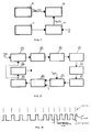
- Figure 1 shows the block diagram of the principle of operation of a chain generating the transmission pulse.
- Cathode modulated power amplifiers are characterized by two parameters which stand for their amplitude and phase sensitivity as a function of the stability of the video modulating pulse V K (t).
- the transmitting system is all the more stable the better the pulse to pulse stability of the modulating signal V K (t) is.
- Processing systems at reception, are generally of the Moving Target Indicator (MTI), Moving Target Detector (MTD) type so as to suppress fixed echoes and detest the moving ones, characterized by Doppler frequencies different than zero.
- MTI Moving Target Indicator
- MTD Moving Target Detector
- Such systems require that the transmission rate varies from pulse to pulse or from group of pulses to group of pulses by an amount which, peak to peak, may reach up to 20% of the mean value.
- modulators we may expect transmission pulses stability of the order of 0.1% with acceptable circuit complexity.
- This value is a penalty of the order of about ten decibel with respect to what can be achieved taking into account the stability which could be required of the other elements of the transmitting and receiving chains and to the possibility of adopting sophisticated processing systems.
- the device for which the patent is applied solves the problem in a consistent and reliable manner: it does not require for the diodes neither technological advances which may be unlikely, and at any rate costly, nor for the power supply operational characteristics which, more than demanding, are essentially unpractical.
- the idea behind the device herin presented is to provide a variation at low voltage of the signal governing the PFN charging circuit so as to compensate for the load ripple variations due to non constant PRF which are introduced into the modulators operation.
- the device is also capable of compensating for the mains ripple, as the integration network time constant is set equal to that of the high voltage power supply filter.
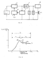
- the error signal reconstruction is achieved through the device shown in figure 2. It can be seen that the device has an input set/reset circuit which generates a square wave having level 1 duration equal to PFN charge time and 1 + ⁇ level equal to the radar frequency as shown in Fig. 3.
- the set level is controlled by the radar PRF and the reset trigger is generated by comparing PFN charge voltage and reference voltage.
- the output waveform from the set/reset circuit controls a switch (2) which discharges the integration network (3) to which it is connected for a time proportional to that of the PFN charging time and charges it for the full time elapsing between the regulating point and the next radar pulse.
- the integration network time constant is made equal to that of the high voltage power supply filter.
- the peak detector (4) charges up to the ripple peak value and provides a signal with an amplitude which varies proportionally with the radar PRF.
- This signal passes through a buffer circuit (5), amplified by an amplifier (6), inverted and sent to a summing network (7) which sums it to the reference voltage.
- a summing network (7) which sums it to the reference voltage.
- a synchronizing signal is generated by the trigger generator (9), which blocks, through the control circuit (10), the charging voltage of the PFN.
- This stabilising device used on modulators within which there are very high voltages, is operating entirely at low voltages and relies upon simple manipulation of signals. It also has a very important propriety, in radar terms: that of being adaptive for the repetition frequency.
- the stability of the modulator controlled by the device which is presented herein reaches values of the order of 0.01% with consequential capability to suppress fixed echoes of the order of 60 dB, with a recovery of 10 dB over solutions which are not equipped with the device described.
Landscapes
- Engineering & Computer Science (AREA)
- Physics & Mathematics (AREA)
- General Physics & Mathematics (AREA)
- Radar, Positioning & Navigation (AREA)
- Electromagnetism (AREA)
- Automation & Control Theory (AREA)
- Computer Networks & Wireless Communication (AREA)
- Remote Sensing (AREA)
- Radar Systems Or Details Thereof (AREA)
- Arrangements For Transmission Of Measured Signals (AREA)
- Near-Field Transmission Systems (AREA)
- Transmitters (AREA)
Claims (1)
- Dispositif de régulation de tension destiné à un système radar, présentant une fréquence radar impulsionnelle pour compenser les variations de tension dans un module de décharge résonnant ayant un réseau de formation d'impulsions (M) et un diviseur haute tension (I) relié à une alimentation de puissance haute tension (F) munie d'un filtre d'alimentation de puissance haute tension, tel que ledit dispositif soit capable de générer un signal pouvant être utilisé dans ledit module de décharge résonnant pour transmetteurs de radar, ledit dispositif comprenant :- un circuit de comparaison (8) relié audit diviseur haute tension (I),- un générateur de synchronisation (9) relié audit circuit de comparaison (8), ledit générateur de synchronisation (9) produisant un signal de synchronisation si une sortie dudit circuit de comparaison est égale à zéro, et- un circuit de commande (10) relié audit générateur de synchronisation (9) et relié audit réseau de formation d'impulsions (M) pour bloquer le chargement dudit réseau de formation d'impulsions (M) à réception dudit signal de synchronisation,
caractérisé par :- un circuit de sommation (7) fournissant un signal de référence actualisé audit circuit de comparaison pour comparaison avec ledit diviseur haute tension (I) ;- un circuit de mise en marche/remise à zéro (1) pour générer une onde carrée possédant une première période égale au temps de charge dudit réseau de formation d'impulsions (M) et une seconde période égale à celle de la fréquence radar impulsionnelle ;- un réseau d'intégration (3) possédant une constante de temps égale à celle du filtre d'alimentation de puissance haute tension,- un commutateur de mise à la terre (2) relié audit circuit de mise en marche/remise à zéro (1) et relié audit réseau d'intégration (3) pour décharger ledit réseau d'intégration pendant ladite première période et le charger pendant ladite seconde période ;- un détecteur de crête (4) relié audit réseau d'intégration (3) pour produire un signal de sortie dont l'amplitude varie proportionnellement à ladite fréquence radar impulsionnelle ;- un amplificateur (6) relié audit détecteur de crête (4) et produisant une sortie correspondant audit signal de sortie amplifié dudit détecteur de crête (4), et en ce que- le circuit de sommation (7) ajoute ladite sortie dudit amplificateur (6) à un signal de référence formant le signal de référence actualisé.
Priority Applications (1)
| Application Number | Priority Date | Filing Date | Title |
|---|---|---|---|
| AT86102570T ATE97751T1 (de) | 1985-02-28 | 1986-02-27 | Spannungsregler fuer leitungsmodulator zur verwendung in sendern bei radaranwendung. |
Applications Claiming Priority (2)
| Application Number | Priority Date | Filing Date | Title |
|---|---|---|---|
| IT8547754A IT1208707B (it) | 1985-02-28 | 1985-02-28 | Regolatore di tensione per modulatori a linea da utilizzare su trasmettitori per applicazioni radar |
| IT4775485 | 1985-02-28 |
Publications (3)
| Publication Number | Publication Date |
|---|---|
| EP0194520A2 EP0194520A2 (fr) | 1986-09-17 |
| EP0194520A3 EP0194520A3 (en) | 1988-11-30 |
| EP0194520B1 true EP0194520B1 (fr) | 1993-11-24 |
Family
ID=11262302
Family Applications (1)
| Application Number | Title | Priority Date | Filing Date |
|---|---|---|---|
| EP86102570A Expired - Lifetime EP0194520B1 (fr) | 1985-02-28 | 1986-02-27 | Régulateur de tension de modulateur de ligne pour transmetteurs appliqués aux radars |
Country Status (5)
| Country | Link |
|---|---|
| US (1) | US4774517A (fr) |
| EP (1) | EP0194520B1 (fr) |
| AT (1) | ATE97751T1 (fr) |
| DE (1) | DE3689313D1 (fr) |
| IT (1) | IT1208707B (fr) |
Families Citing this family (2)
| Publication number | Priority date | Publication date | Assignee | Title |
|---|---|---|---|---|
| US4996494A (en) * | 1989-06-15 | 1991-02-26 | The United States Of America As Represented By The Secretary Of The Air Force | Droop compensated PFN driven transformer for generating high voltage, high energy pulses |
| US4975706A (en) * | 1989-11-06 | 1990-12-04 | Raytheon Company | Radar system |
Family Cites Families (10)
| Publication number | Priority date | Publication date | Assignee | Title |
|---|---|---|---|---|
| US2644088A (en) * | 1945-03-22 | 1953-06-30 | Us Sec War | Radar power supply system |
| US3298025A (en) * | 1965-07-08 | 1967-01-10 | Jr Harry J Fumea | Pulse to pulse power control system |
| US3445754A (en) * | 1966-12-09 | 1969-05-20 | Samuel L Broadhead Jr | Reference oscillator and vco loop controlled dc regulator |
| US3740640A (en) * | 1970-10-08 | 1973-06-19 | Westinghouse Electric Corp | Radar power supply |
| US3760256A (en) * | 1972-07-31 | 1973-09-18 | Us Army | Synchronous dc power supply |
| US4097863A (en) * | 1976-08-06 | 1978-06-27 | Raytheon Company | Marine radar system with independent switched power supplies |
| US4104564A (en) * | 1976-12-27 | 1978-08-01 | Venus Scientific Inc. | High switching speed high voltage power supply |
| DE2932791A1 (de) * | 1979-08-13 | 1981-02-19 | Siemens Ag | Schaltungsanordnung zur erzeugung einer konstanten versorgungsspannung fuer eine pulsierende last |
| GB2104326B (en) * | 1981-08-08 | 1984-11-21 | Marconi Co Ltd | A pulse generator |
| FR2590745B1 (fr) * | 1982-05-14 | 1988-06-10 | Dassault Electronique | Dispositif d'alimentation electrique pour radar |
-
1985
- 1985-02-28 IT IT8547754A patent/IT1208707B/it active
-
1986
- 1986-02-27 AT AT86102570T patent/ATE97751T1/de not_active IP Right Cessation
- 1986-02-27 EP EP86102570A patent/EP0194520B1/fr not_active Expired - Lifetime
- 1986-02-27 DE DE86102570T patent/DE3689313D1/de not_active Expired - Lifetime
-
1987
- 1987-05-18 US US07/052,135 patent/US4774517A/en not_active Expired - Fee Related
Also Published As
| Publication number | Publication date |
|---|---|
| DE3689313D1 (de) | 1994-01-05 |
| EP0194520A2 (fr) | 1986-09-17 |
| ATE97751T1 (de) | 1993-12-15 |
| IT1208707B (it) | 1989-07-10 |
| IT8547754A0 (it) | 1985-02-28 |
| EP0194520A3 (en) | 1988-11-30 |
| US4774517A (en) | 1988-09-27 |
Similar Documents
| Publication | Publication Date | Title |
|---|---|---|
| US5477226A (en) | Low cost radar altimeter with accuracy enhancement | |
| US4017856A (en) | Self-calibrating microwave transponder | |
| US4533871A (en) | Range-enable information system for plural mobile objects | |
| US5719582A (en) | Software/hardware digital signal processing (DSP) altimeter | |
| US4066965A (en) | RF GTWT Saturating circuit | |
| US4047173A (en) | FM pulse compression radar | |
| US4161732A (en) | Gated pulse compression radar | |
| US4144533A (en) | Automatic gain control circuit for a pulsed radar | |
| EP0194520B1 (fr) | Régulateur de tension de modulateur de ligne pour transmetteurs appliqués aux radars | |
| US4051473A (en) | Input tracking threshold detector | |
| US5053772A (en) | Radar system employing a method for motion and range closure compensation | |
| US4425515A (en) | Method and means to minimize risetime of a microwave pulse modulated signal from a frequency multiplier circuit | |
| US5055850A (en) | Waveform generator | |
| EP0427469B1 (fr) | Système à radar | |
| US3365718A (en) | Device for disturbance suppression in a radar equipment | |
| US2822538A (en) | Pulse power control | |
| EP0106340B1 (fr) | Dispositif d'élimination automatique des échos radar non-désirés | |
| US3092778A (en) | Improved sweep integrator system | |
| US5111206A (en) | Velocity deception apparatus | |
| EP0867730B1 (fr) | Procédé et dispositif pour compenser les variations de la tension d'alimentation | |
| US3706038A (en) | Pulse transmitter including means for controlling the amplitude and phase of output pulses | |
| US4165492A (en) | Recirculation circuit for repetition of an analog pulse signal | |
| US4755740A (en) | Circuit for power pulse amplitude stabilization in radar transmitter pulse modulator or the like | |
| JPH0472588A (ja) | パルスドチャープレーダ送信変調信号の形成方法およびパルスドチャープレーダ装置 | |
| US6359524B1 (en) | Modulation pulse-top ripple compensation for a travelling wave tube pulser |
Legal Events
| Date | Code | Title | Description |
|---|---|---|---|
| PUAI | Public reference made under article 153(3) epc to a published international application that has entered the european phase |
Free format text: ORIGINAL CODE: 0009012 |
|
| AK | Designated contracting states |
Kind code of ref document: A2 Designated state(s): AT BE CH DE FR GB LI NL SE |
|
| PUAL | Search report despatched |
Free format text: ORIGINAL CODE: 0009013 |
|
| AK | Designated contracting states |
Kind code of ref document: A3 Designated state(s): AT BE CH DE FR GB LI NL SE |
|
| 17P | Request for examination filed |
Effective date: 19890527 |
|
| 17Q | First examination report despatched |
Effective date: 19901228 |
|
| GRAA | (expected) grant |
Free format text: ORIGINAL CODE: 0009210 |
|
| AK | Designated contracting states |
Kind code of ref document: B1 Designated state(s): AT BE CH DE FR GB LI NL SE |
|
| PG25 | Lapsed in a contracting state [announced via postgrant information from national office to epo] |
Ref country code: SE Effective date: 19931124 Ref country code: DE Effective date: 19931124 Ref country code: AT Effective date: 19931124 |
|
| REF | Corresponds to: |
Ref document number: 97751 Country of ref document: AT Date of ref document: 19931215 Kind code of ref document: T |
|
| PGFP | Annual fee paid to national office [announced via postgrant information from national office to epo] |
Ref country code: BE Payment date: 19931223 Year of fee payment: 9 |
|
| ET | Fr: translation filed | ||
| REF | Corresponds to: |
Ref document number: 3689313 Country of ref document: DE Date of ref document: 19940105 |
|
| PG25 | Lapsed in a contracting state [announced via postgrant information from national office to epo] |
Ref country code: GB Effective date: 19940227 |
|
| PG25 | Lapsed in a contracting state [announced via postgrant information from national office to epo] |
Ref country code: LI Effective date: 19940228 Ref country code: CH Effective date: 19940228 |
|
| PG25 | Lapsed in a contracting state [announced via postgrant information from national office to epo] |
Ref country code: NL Effective date: 19940901 |
|
| PLBE | No opposition filed within time limit |
Free format text: ORIGINAL CODE: 0009261 |
|
| STAA | Information on the status of an ep patent application or granted ep patent |
Free format text: STATUS: NO OPPOSITION FILED WITHIN TIME LIMIT |
|
| NLV4 | Nl: lapsed or anulled due to non-payment of the annual fee | ||
| GBPC | Gb: european patent ceased through non-payment of renewal fee |
Effective date: 19940227 |
|
| PG25 | Lapsed in a contracting state [announced via postgrant information from national office to epo] |
Ref country code: FR Effective date: 19941031 |
|
| REG | Reference to a national code |
Ref country code: CH Ref legal event code: PL |
|
| 26N | No opposition filed | ||
| REG | Reference to a national code |
Ref country code: FR Ref legal event code: ST |
|
| PG25 | Lapsed in a contracting state [announced via postgrant information from national office to epo] |
Ref country code: BE Effective date: 19950228 |
|
| BERE | Be: lapsed |
Owner name: SELENIA INDUSTRIE ELETTRONICHE ASSOCIATE S.P.A. Effective date: 19950228 |