EP0194551A2 - Structure pour le montage d'un tambour de frein au moyen d'une roue de bicyclette - Google Patents
Structure pour le montage d'un tambour de frein au moyen d'une roue de bicyclette Download PDFInfo
- Publication number
- EP0194551A2 EP0194551A2 EP86102797A EP86102797A EP0194551A2 EP 0194551 A2 EP0194551 A2 EP 0194551A2 EP 86102797 A EP86102797 A EP 86102797A EP 86102797 A EP86102797 A EP 86102797A EP 0194551 A2 EP0194551 A2 EP 0194551A2
- Authority
- EP
- European Patent Office
- Prior art keywords
- hub
- threaded
- section
- drum
- brake drum
- Prior art date
- Legal status (The legal status is an assumption and is not a legal conclusion. Google has not performed a legal analysis and makes no representation as to the accuracy of the status listed.)
- Withdrawn
Links
Images


Classifications
-
- B—PERFORMING OPERATIONS; TRANSPORTING
- B62—LAND VEHICLES FOR TRAVELLING OTHERWISE THAN ON RAILS
- B62K—CYCLES; CYCLE FRAMES; CYCLE STEERING DEVICES; RIDER-OPERATED TERMINAL CONTROLS SPECIALLY ADAPTED FOR CYCLES; CYCLE AXLE SUSPENSIONS; CYCLE SIDECARS, FORECARS, OR THE LIKE
- B62K19/00—Cycle frames
- B62K19/30—Frame parts shaped to receive other cycle parts or accessories
- B62K19/38—Frame parts shaped to receive other cycle parts or accessories for attaching brake members
-
- B—PERFORMING OPERATIONS; TRANSPORTING
- B62—LAND VEHICLES FOR TRAVELLING OTHERWISE THAN ON RAILS
- B62L—BRAKES SPECIALLY ADAPTED FOR CYCLES
- B62L1/00—Brakes; Arrangements thereof
- B62L1/02—Brakes; Arrangements thereof in which cycle wheels are engaged by brake elements
Definitions
- This invention relates to a bicycle hub brake assembly including a brake drum and a brake band, and more particularly to an improved structure for mounting the brake drum to a bicycle wheel hub.
- the bicycle hub brake assembly generally has a brake band which, when actuated, comes into braking contact with a cylindrical wall of a brake drum co-rotatably mounted on a cylindrical end portion of a bicycle wheel hub.
- the conventional structure for mounting the brake drum to the hub is disclosed in Page 376 of "JAPANESE INDUSTRIAL STANDARD, Classification and Symbols of Bicycle, 1975" edited in English by Japanese Industrial Standard Association.
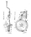
- the bicycle hub brake assembly comprises a brake drum 2 fixed on an enlarged cylindrical end portion 1a of a bicycle wheel hub 1.
- the drum 2 has an outer cylindrical portion 7a and an inner cylindricaf boss portion 7b which is internally threaded at 8 for screwing engagement with an externally threaded section 9 on the hub end portion 1a.
- An axially inner extremity of the hub end portion 1a is formed with an integral spoke mounting flange 1b.
- the brake drum 1 is surrounded by a flexible brake band 5 which usually consists of an outer metal layer 5a and an inner lining layer 5b. Both of the brake drum 2 and the brake band 5 are housed within a hollow casing or cover 3.
- the brake band 5 is connected at its one end 5a to the cover 3, and at its the other end 5d to a free end of one arm 4a of a bell crank 4 which is pivotally mounted at its center on a support shaft 4c.
- the other arm 4b of the bell crank 4 is pivotally connected at its free end to a reciprocatingly movable control rod 6 which is connected to a known remote brake lever (not shown).
- the arm 4a, and hence the bell crank 4 is always urged cfockwise in Figure 4 by a return spring 10 so as to normally keep the brake band 5 away from the circumferential wall of the outer cylindrical portion 7a of the drum 4 .
- a narrow clearance C exists between the lining layer 5b of the brake band 5 and the circumferential wall of the outer cylindrical portion 7a of the drum 7 when the brake lever is in its inactive position.
- this type of bicycle brake assembly is self-encouraging in braking performance, in addition to that the braking contact area between the band 5 and the drum 2 is large enough to impart an effective braking force to the wheel hub 1. Therefore, as far as the braking ability is concerned, the hub brake assembly is superior to a known caliper type bicycle brake assembly which is quite limited in braking contact area between a pair of small brake shoes and a bicycle wheel rim.
- the hub brake assembly is in fact used predominantly for relatively low price bicycles (including the so-called mini bicycles) but quite rarely for high class or sport type bicycles- This is considered attributable to the following reason.
- spoke replacement requires insertion of a new spoke through a corresponding one of a plurality of spoke mounting holes (not shown in Figures 1 and 2 but shown in Figures 1 and 2) formed in the hub flange 1b, such spoke insertion is inevitably hindered by the non-removable brake drum 2 because the drum 2 is larger in diameter than the hub flange 1b.
- an object of the present invention to provide an improved structure for mounting a brake drum to a bicycle wheel hub which enables ready removal of the brake drum from the wheel hub for replacement of a spoke or spokes.
- Another object of the invention is to provide an improved structure for mounting a brake drum to a bicycle wheel hub which is free from development of impermissible internal stress in the boss portion of the brake drum.
- a structure for mounting a brake drum to a bicycle wheel hub comprising the brake drum having an inner cylindrical boss portion fittable on a cylindrical end portion of the hub, the cylindrical end portion having an externally threaded outermost section and a non-threaded section located adjacent to the threaded outermost section, the non-threaded section having a plurality of spaced spline grooves formed in its external wall so as to extend axially of the hub to terminate in the threaded outermost section, the inner cylindrical boss portion having a plurality of spaced internal projections formed therewith so as to extend axially of the hub for engagement with the spline grooves, and a lock nut removably screwed on the threaded outermost section.
- a bicycle wheel hub 11 is rotatably mounted on a stationary hub spindle 12 which is fixed at its opposite ends to a pair of spaced end plates (not shown) of a bicycle frame in a manner known per se.
- the hub 11 is supported rotatably on the spindle 12 by means of ball bearings.
- Each ball bearing includes a cup-shaped outer race member 13 rigid to an internal surface of the hub, a hub cone 14 screwed on the spindle 12 to provide a conical inner race, and steel balls 15 interposed between the races 13 and 14.
- One end of the hub 11 is formed with an enlarged cylindrical portion 11 a and an integral flange 17 in which a number of regularly spaced spoke mounting holes 17a are formed conventionally.
- a brake drum 16 according to the present invention is mounted on the cylindrical hub end portion 11 a in a manner quite different from the conventional manner as already described in the foregoing.
- the hub end portion 11 a is formed with a diametrically reduced cylindrical end section 11b.
- a plurality of spline grooves 18, preferably regularly spaced, are formed in the wall thickness of the section 11 b.
- the spline grooves 18 extend in parallel with an axis of the hub 11.
- the spline grooves 18 start from an annular vertical wall 11 defining the reduced section 11 b and terminate in an externally threaded outermost section 19 whose external cylindrical surface wall is substantially flush with bottom walls 18a of the spline grooves 18 so that the drum 16 can be coupled onto the hub end portion 11 a through this section 19.
- this sec- ion 19 may have a smaller diameter than the non-threaded section 11 b for the same purpose.
- the brake drum 16 which may be press-formed from a single flat plate, comprises an outer cylindrical portion 20 and an inner cylindrical boss portion 21 which is substantially corrugated to provide a plurality of axially extending projections 22 for intimate engagement with the spline grooves 18.
- the inner boss portion 21 of the drum 16 is axially coupled onto the end portion 11 a of the hub 11 to bring the axial projections 22 into engagement with the spline grooves 18. Subsequently, a lock nut 23 is screwed on the threaded section 19 of the end portion 11 a and tightened up enough to prevent the axial displacement of the drum 16 relative to the hub 11.
- the lock nut 23 in no way takes part in the torque transmission from the brake drum 16 to the hub 11 but merely serves the sole purpose of preventing unexpected detachment, from the hub 11, of the drum 16 which is otherwise movable axially relative to the hub 16.
- .repeated braking operations accompanied by great torque development will not result in excessive or irreversible tightening of the lock nut 23, which enables the nut 23 to be readily removed for subsequent removal of the brake drum 16 when such is desired for example for spoke replacement.
- the brake drum mounting structure has been described hereinbefore with reference to Figures 1 to 4 illustrating an external type hub brake assembly having the brake band arranged externally of the brake drum.
- the same mounting structure is also applicable to a known expanding type hub brake assembly having a brake band arranged internally of the brake drum.
- the inner cylindrical boss portion 21 of the brake drum 16 may be provided internally with a plurality of axially extending spline grooves into which are fitted a plurality of axially extending projections formed on the outer periphery of the hub end portion 11 a.
- the spline grooves 18 and the engaging projections 22 may be slightly spiral with respect to the axis of the hub 11, so that a braking force exerted on the brake drum 16 can produce a force component tending to urge the drum 16 axially inwardly to prevent unexpected loosing of the lock. nut 23.
Landscapes
- Engineering & Computer Science (AREA)
- Mechanical Engineering (AREA)
- Braking Arrangements (AREA)
Applications Claiming Priority (2)
| Application Number | Priority Date | Filing Date | Title |
|---|---|---|---|
| JP30727/85U | 1985-03-04 | ||
| JP3072785U JPS61146634U (fr) | 1985-03-04 | 1985-03-04 |
Publications (2)
| Publication Number | Publication Date |
|---|---|
| EP0194551A2 true EP0194551A2 (fr) | 1986-09-17 |
| EP0194551A3 EP0194551A3 (fr) | 1987-04-08 |
Family
ID=12311692
Family Applications (1)
| Application Number | Title | Priority Date | Filing Date |
|---|---|---|---|
| EP86102797A Withdrawn EP0194551A3 (fr) | 1985-03-04 | 1986-03-04 | Structure pour le montage d'un tambour de frein au moyen d'une roue de bicyclette |
Country Status (2)
| Country | Link |
|---|---|
| EP (1) | EP0194551A3 (fr) |
| JP (1) | JPS61146634U (fr) |
Cited By (2)
| Publication number | Priority date | Publication date | Assignee | Title |
|---|---|---|---|---|
| US7540361B2 (en) * | 2005-06-17 | 2009-06-02 | Shimano Inc. | Roller brake mounting adapter |
| USRE42986E1 (en) | 2001-08-30 | 2011-12-06 | Shimano Inc. | Bicycle disc brake hub |
Family Cites Families (5)
| Publication number | Priority date | Publication date | Assignee | Title |
|---|---|---|---|---|
| US2300293A (en) * | 1940-03-20 | 1942-10-27 | Continental Aviat & Eng Corp | Shafting |
| FR2423678A1 (fr) * | 1978-04-20 | 1979-11-16 | Bes Francis | Roue libre de velo interchangeable instantanement |
| JPS5934132B2 (ja) * | 1978-09-25 | 1984-08-20 | 三協アルミニウム工業株式会社 | スズ含有スラッジの処理方法 |
| JPS58121332A (ja) * | 1982-01-11 | 1983-07-19 | Nissan Motor Co Ltd | ブレ−キドラム |
| JPS59103035A (ja) * | 1982-12-02 | 1984-06-14 | Bridgestone Cycle Co | 自転車用バンドブレ−キ装置 |
-
1985
- 1985-03-04 JP JP3072785U patent/JPS61146634U/ja active Pending
-
1986
- 1986-03-04 EP EP86102797A patent/EP0194551A3/fr not_active Withdrawn
Cited By (2)
| Publication number | Priority date | Publication date | Assignee | Title |
|---|---|---|---|---|
| USRE42986E1 (en) | 2001-08-30 | 2011-12-06 | Shimano Inc. | Bicycle disc brake hub |
| US7540361B2 (en) * | 2005-06-17 | 2009-06-02 | Shimano Inc. | Roller brake mounting adapter |
Also Published As
| Publication number | Publication date |
|---|---|
| JPS61146634U (fr) | 1986-09-10 |
| EP0194551A3 (fr) | 1987-04-08 |
Similar Documents
| Publication | Publication Date | Title |
|---|---|---|
| US5535855A (en) | Bicycle hub brake | |
| US6106077A (en) | Wheel bolt | |
| CN100528680C (zh) | 自行车用曲柄的固定结构 | |
| US5062318A (en) | Bicycle gear crank assembly | |
| CA2636390A1 (fr) | Moyeu de roue pourvu d'evidements axiaux formes entre les trous destines a des boulons de roue | |
| US6837341B2 (en) | Apparatus for mounting a brake drum to a bicycle frame | |
| US4964490A (en) | Pin type disc brake | |
| EP1371546B2 (fr) | Dispositif pour un frein à moyeu pour bicyclettes | |
| US20060283644A1 (en) | Bicycle wheel driving device | |
| US6793045B2 (en) | Apparatus for retaining a brake drum to a fastening bracket | |
| EP1375935B2 (fr) | Dispositif d'actionnement pour un dispositif de commande pour bicyclette | |
| US6978867B2 (en) | Bicycle hub with an attached cooling disk | |
| EP0122143B1 (fr) | Dispositif de roulement pour roue arrière d'un véhicule | |
| EP1391325B1 (fr) | Moyeu de bicyclette avec un système de réglage de la force de freinage accessible de l'extérieur | |
| US20060284472A1 (en) | Brakable wheel hub device | |
| US7540361B2 (en) | Roller brake mounting adapter | |
| JP2604091B2 (ja) | クラッチカバー組立体のプレッシャープレート取り付け構造 | |
| GB2104985A (en) | Disc brakes | |
| JP3267132B2 (ja) | アクスル構造 | |
| CN100534855C (zh) | 自行车车轮驱动装置 | |
| KR100285412B1 (ko) | 드럼식 브레이크의 어져스터구조 | |
| JPS646420Y2 (fr) | ||
| EP0194551A3 (fr) | Structure pour le montage d'un tambour de frein au moyen d'une roue de bicyclette | |
| EP1733962A2 (fr) | Dispositif d'entraînement pour une roue de bicyclette | |
| JPH022753B2 (fr) |
Legal Events
| Date | Code | Title | Description |
|---|---|---|---|
| PUAI | Public reference made under article 153(3) epc to a published international application that has entered the european phase |
Free format text: ORIGINAL CODE: 0009012 |
|
| AK | Designated contracting states |
Kind code of ref document: A2 Designated state(s): BE DE GB NL SE |
|
| PUAL | Search report despatched |
Free format text: ORIGINAL CODE: 0009013 |
|
| AK | Designated contracting states |
Kind code of ref document: A3 Designated state(s): BE DE GB NL SE |
|
| STAA | Information on the status of an ep patent application or granted ep patent |
Free format text: STATUS: THE APPLICATION IS DEEMED TO BE WITHDRAWN |
|
| 18D | Application deemed to be withdrawn |
Effective date: 19871009 |
|
| RIN1 | Information on inventor provided before grant (corrected) |
Inventor name: OZAKI, NOBUO |