EP0194561A1 - Joint tournant - Google Patents
Joint tournant Download PDFInfo
- Publication number
- EP0194561A1 EP0194561A1 EP86102843A EP86102843A EP0194561A1 EP 0194561 A1 EP0194561 A1 EP 0194561A1 EP 86102843 A EP86102843 A EP 86102843A EP 86102843 A EP86102843 A EP 86102843A EP 0194561 A1 EP0194561 A1 EP 0194561A1
- Authority
- EP
- European Patent Office
- Prior art keywords
- stator
- rotor
- outlets
- rotary feedthrough
- rotary
- Prior art date
- Legal status (The legal status is an assumption and is not a legal conclusion. Google has not performed a legal analysis and makes no representation as to the accuracy of the status listed.)
- Granted
Links
Images


Classifications
-
- E—FIXED CONSTRUCTIONS
- E21—EARTH OR ROCK DRILLING; MINING
- E21C—MINING OR QUARRYING
- E21C35/00—Details of, or accessories for, machines for slitting or completely freeing the mineral from the seam, not provided for in groups E21C25/00 - E21C33/00, E21C37/00 or E21C39/00
- E21C35/22—Equipment for preventing the formation of, or for removal of, dust
- E21C35/23—Distribution of spraying-fluids in rotating cutter-heads
-
- F—MECHANICAL ENGINEERING; LIGHTING; HEATING; WEAPONS; BLASTING
- F16—ENGINEERING ELEMENTS AND UNITS; GENERAL MEASURES FOR PRODUCING AND MAINTAINING EFFECTIVE FUNCTIONING OF MACHINES OR INSTALLATIONS; THERMAL INSULATION IN GENERAL
- F16L—PIPES; JOINTS OR FITTINGS FOR PIPES; SUPPORTS FOR PIPES, CABLES OR PROTECTIVE TUBING; MEANS FOR THERMAL INSULATION IN GENERAL
- F16L27/00—Adjustable joints; Joints allowing movement
- F16L27/08—Adjustable joints; Joints allowing movement allowing adjustment or movement only about the axis of one pipe
- F16L27/087—Joints with radial fluid passages
Definitions
- the invention relates to a rotating union for loading the cutting edges of tools of tunneling and mining machines for mining or tunneling with a liquid, consisting of a stator connected to a liquid supply and a rotor surrounding it with several outlets for spraying the cutting edges of the tools. wherein the stator and the rotor are connected to one another for the passage of the liquid via channels or the like.
- stator and rotor are made of cast iron or cast steel, so that there is no lubricating effect when water flows through them, which leads to high abrasion and thus to heavy wear and also to corrosion with a severe impairment of the service life of these parts of the known rotary unions.
- the invention has for its object to provide a rotary union of the type mentioned using the aforementioned disadvantages, which is easy to manufacture and assemble, has a long life and also has a sectoral spraying of the cutting edges of tools of the associated machine.
- this is achieved in that the outlets of the rotor radially penetrate them and at least one radially arranged channel of the stator is assigned to them, which opens into an axially extending channel of the stator.
- This configuration ensures that only one very specific sector of the tools, for example a milling drum, is sprayed with water in each cycle, specifically the tools that are in engagement with the material to be cut. This leads to a very considerable reduction in water consumption and the possibility of using pumps with a lower output, but the cooling of the tools and dust control are ensured in the same way as before.
- the outlets of the rotor are equipped with Büchserr, one end face of which rests on the circumference of the stator, while the other end faces of the sleeves are under the action of springs.
- the sleeves are thus under the spring action on the stator, so that there is surface contact between the moving parts, which leads to a low surface pressure, so that even when water passes through, there is practically no wear.
- the stator advantageously has in the movement area of the outlets an end part of the rotor, which is connected to the remaining part of the stator by means of screw bolts
- This design makes it possible to replace this end part of the stator by loosening the screw boices from the outside, so that, for example, another sector can be coated.
- one or more recesses or recesses extending in the circumferential direction thereof are or are made and dimensioned in the circumferential area of the stator in the range of motion of the outlets of the rotor such that they each have at least two adjacent outlets of the rotor with the radial channel of the Stator connects or connect. In this way too, a very specific setting of a desired sector is possible for spraying the machine tools that are in engagement.
- stator For this purpose, several can be in the stator. preferably three radial channels start from the axial feed channel, so that a very specific sparkling wine is also sprayed with tools.
- At least one end part of the stator and / or the sleeves of the outlets of the rotor are made of ceramic, so that not only is corrosion with certainty ruled out. but also due to the water to be pumped, which has no lubricating effect, wear cannot occur.
- the stator extends with its end surrounding the rotor into a bushing, which is closed at one end by means of a bottom and has at least one, through this radially penetrating, flush alignment with the radial channel of the stator, the end part according to the aforementioned embodiment is therefore no longer placed in front of the stator, - but surrounds it in the form of a sleeve, so that the end of the stator extends to the bottom of the sleeve. In this way, a build-up of pressure between the stator and the end part according to the aforementioned embodiment is excluded.
- the bottom of the sleeve is penetrated by bolts that are screwed axially into the stator. By loosening these screws, the entire distributor housing can be quickly and easily removed and / or stiffened.
- a piece of pipe is advantageously pushed onto the bush, which is equipped with radial openings corresponding to the number of outlets of the rotor, which are connected to the outlets of the rotor.
- This pushed tube piece replaces the individual sleeves in the outlets of the rotor according to the aforementioned embodiment, so that there is only one component that is much easier to manufacture than the individual sleeves to be adapted exactly to the circumference of the stator. In this version, a little more leakage is accepted than in the case of the aforementioned version, but this is easy when exposed to water possible and far outweighs the considerably more complex production.
- the pipe section is inserted into a correspondingly shaped recess in the rotor, so that a compact construction results.
- the rear end of the stator is coupled to a swivel drive and the end of the stator surrounded by one or more rotors in its area in the area of the outlets of the rotor or the Rotors is equipped with one or more ring grooves which extend over a part of the circumference of the stator.
- the rotor advantageously consists of a disk which is penetrated radially by the outlets.
- the rotor advantageously consists of a disk which is penetrated radially by the outlets.
- the starter has a longitudinal channel, which is connected to the outlets of the associated rotor via a radial channel connected to it
- the annular groove extends, for example, over an angular range of 150 degrees. If there are several rotors, for example two, the ring grooves assigned to their outlets overlap by a certain range.
- the annular grooves can, for example, each cover areas of 90 degrees and can also be offset from one another by such an area, although there is a certain overlap area.
- the rotary leadthrough is either built into a tunneling and mining machine in a conventional manner or rotates synchronously with its roller equipped with tools so that the individual tools are sprayed with water.
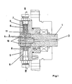
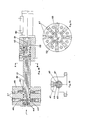
- the rotary feedthrough consists of the stator 1, which has an axial channel 2 which merges into the radial channel 4 in the end part 3.
- the axial channel 2 of the stator is connected to a liquid supply, not shown.
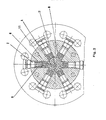
- the stator 1 is surrounded by the rotor 5, which has a plurality of outlets 6 penetrating it radially.
- a total of six outlets arranged in the form of a stem are used, but the number is arbitrary.
- connecting pieces 7 are screwed, to which connecting lines, not shown, are connected, for example in the form of hoses, which are guided to the nozzles of the individual tools, for example a milling drum.
- the rotor rotates synchronously with the milling drum.
- outlets 6 of the rotor 5 are equipped with sleeves 8, one end faces of which rest on the circumferential surface of the end part 3 of the stator 1, while the other end faces of the sleeves 8 are under the action of springs 9, which in turn are supported on the connecting piece 7 .
- the end part 3 of the stator 1 is fastened to it by means of the externally accessible screw bolts 10, so that the end part can be replaced easily and quickly, for example in order to be able to change the sector of the machine tools to be sprayed.
- the channels 1 1 are aligned with the radial channel 4 of the end part 3 of the stator 1, so that the liquid emerging from the radial channel 4 exits the outlets 6 centrally through the channels 11 of the bushings 8.
- the recess 12 is mounted and dimensioned such that these two channels 11 of the cans 8 of two adjacent outlets 6 connects to the radial channel 4 of the end part 3 of the stator 1.
- a very specific sector is thus formed because continuously new outlets with their channels continuously enter the area of the recess 12 and leave them further at a certain angle, as a result of which the pressure medium supply in these outlets is opened or closed.
- the recess is designed to overlap both at its beginning and at its end region.
- a plurality of radial channels 4 are provided in the end part 3 of the stator 1, so that a very specific sector can also be set in this way.
- three adjacent outlets are thus constantly connected to the pressure medium supply.
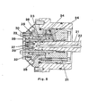
- the rotary feedthrough consists of the stator 21, which has an axial channel 22 which merges into the radial channel 24.
- the axial channel 22 of the stator 21 is connected to a liquid supply, not shown in more detail.
- the stator 21 is surrounded by the rotor 25, which has a plurality of outlets 26 passing through it.
- a total of six outlets arranged in a star shape are used, but the number is arbitrary.
- connecting pieces are screwed, to which connecting lines, not shown, are connected, for example in the form of hoses, which are guided to the nozzles of the individual tools, for example a milling drum.
- the rotor rotates synchronously with the milling drum.
- the stator 21 extends with its end surrounded by the rotor 25 into a sleeve 23 which is closed at one end with a base 27, against which the end face of the rotor 21 bears.
- the sleeve 23 with bottom 27 replaces the end portion in the embodiment of Figure 1 -Figur. 4
- the bushing 23 has at least one passage opening 28 which penetrates it radially and is aligned with the radial channel 24 of the stator 21.
- the bottom 27 of the sleeve 23 is penetrated by screw bolts 29 which are screwed axially into the stator 21. By loosening these bolts 29, the entire distributor housing can be removed and / or adjusted.
- the distributor housing of the rotor 25 is held by means of the screw bolts 30, whereby all parts thereof are connected to one another by the screw bolts 31.
- a tube piece 32 is pushed onto the bushing 23 and, in accordance with the number of outlets 26 of the rotor 25, is equipped with radial passages 33 which are connected to the outlets 26 of the rotor 25.
- the pipe section 32 is inserted into a correspondingly designed recess in the rotor 25
- the pipe section 23 replaces the bushings in the individual outlets 26 in the embodiment according to FIGS. 1 to 4.
- the recess In the sleeve 23 of the channels is in its circumferential surface in the movement area of the pipe piece 32 extending in the circumferential direction of the sleeve 33 recess 3 4 attached 33 and dimensioned such that these two channels 33 of the pipe section 32 with the radial channel 24 of the stator 21 connects
- a very specific sector is formed because continuously new outlets 26 are caught with their channels in the region of the recess 34 and leave them again at a certain angle, as a result of which the pressure medium supply into these outlets is opened or closed.
- the recess is designed to overlap both at its beginning and at its end region.
- the sleeve 23 and / or the pipe section 32 are made of ceramic so that not only corrosion is excluded with certainty, but also wear caused by the water to be pumped, which has no lubricating effect.
- the rotary feedthrough consists of the stator 41, which has an axial channel 42 which merges into the radial channel 4 4 at one end 43.
- the axial channel 4 2 of the stator 41 projects over another radial one Channel at its other end 45 in connection with a liquid supply, not shown.
- the stator 41 is surrounded by the rotor, which has a plurality of outlets 47 penetrating it radially
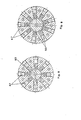
- a total of six are used in the embodiment according to FIG. 7, eight in the case of FIG. 8 and nine in the form of a stem in the case of FIG. 9, the number of which is arbitrary, as the exemplary embodiments show.
- connection pieces In the outer ends of the outlets 47 are screwed connection pieces, not shown, to which connecting lines, for example in the form of hoses, are connected, which are guided to the nozzles of the individual tools, for example a milling drum.
- the rotor 46 rotates synchronously with the milling drum.
- outlets 47 of the rotor 46 are equipped with sleeves 48, one end faces of which rest on the circumferential surface of one end 43 of the stator 41, while the other end faces of the sleeves 48 are under the action of springs 49, which in turn are again on inserts of the outlets 47 support.
- the rear end 45 of the stator 41 is coupled to a swivel drive 50, which engages with its drive journal 5 1 in a this adapted in their shaping recess 52nd
- the annular groove 53 extends over an angular range of preferably 150 degrees.
- the annular groove extends over a range of 1 90-200 degrees, while in the embodiment according to FIG. 9 two annular grooves 53 are provided, of which the upper one in the drawing extends approximately over 180 degrees, while the one in FIG the drawing below is about 160 degrees.
- the stator 41 executes a swivel movement, so that the annular groove 53 now comes into contact with a new sectoral area of the outlets 4 7.
- two rotors 46 are provided, which are combined to form one structural unit.
- a radial channel 44 of the stator 4 1 is assigned to each rotor 46.
- the radial channels 44 each open into separate axial channels 42 of the stator 4 1 . These are connected at the end 4 5 of the stator to a liquid supply, not shown.
- the two ring grooves 53 of the stator 41 assigned to the individual rotors 46 overlap to a certain extent, so that there is an overlap of the sec torial areas
Landscapes
- Engineering & Computer Science (AREA)
- General Engineering & Computer Science (AREA)
- Mechanical Engineering (AREA)
- Mining & Mineral Resources (AREA)
- Life Sciences & Earth Sciences (AREA)
- General Life Sciences & Earth Sciences (AREA)
- Geochemistry & Mineralogy (AREA)
- Geology (AREA)
- Joints Allowing Movement (AREA)
Priority Applications (1)
| Application Number | Priority Date | Filing Date | Title |
|---|---|---|---|
| AT86102843T ATE40179T1 (de) | 1985-03-07 | 1986-03-04 | Drehdurchfuehrung. |
Applications Claiming Priority (6)
| Application Number | Priority Date | Filing Date | Title |
|---|---|---|---|
| DE19853508076 DE3508076A1 (de) | 1985-03-07 | 1985-03-07 | Drehdurchfuehrung |
| DE3508076 | 1985-03-07 | ||
| DE19853528441 DE3528441A1 (de) | 1985-08-08 | 1985-08-08 | Drehdurchfuehrung |
| DE3528441 | 1985-08-08 | ||
| DE19853539226 DE3539226A1 (de) | 1985-11-05 | 1985-11-05 | Drehdurchfuehrung |
| DE3539226 | 1985-11-05 |
Publications (2)
| Publication Number | Publication Date |
|---|---|
| EP0194561A1 true EP0194561A1 (fr) | 1986-09-17 |
| EP0194561B1 EP0194561B1 (fr) | 1989-01-18 |
Family
ID=27192870
Family Applications (1)
| Application Number | Title | Priority Date | Filing Date |
|---|---|---|---|
| EP86102843A Expired EP0194561B1 (fr) | 1985-03-07 | 1986-03-04 | Joint tournant |
Country Status (2)
| Country | Link |
|---|---|
| EP (1) | EP0194561B1 (fr) |
| DE (1) | DE3661855D1 (fr) |
Cited By (2)
| Publication number | Priority date | Publication date | Assignee | Title |
|---|---|---|---|---|
| FR2613456A1 (fr) * | 1987-03-31 | 1988-10-07 | Glyco Antriebstechnik Gmbh | Dispositif de passage tournant, pour transferer des fluides sous pression d'une partie fixe a une partie rotative de machine |
| EP2633219A4 (fr) * | 2010-10-27 | 2016-06-08 | Roxar Flow Measurement As | Raccord |
Families Citing this family (1)
| Publication number | Priority date | Publication date | Assignee | Title |
|---|---|---|---|---|
| DE102023133841A1 (de) * | 2023-12-04 | 2025-06-05 | Arburg Gmbh + Co Kg | Drehdurchführung |
Citations (8)
| Publication number | Priority date | Publication date | Assignee | Title |
|---|---|---|---|---|
| GB1110763A (en) * | 1963-10-29 | 1968-04-24 | Coal Industry Patents Ltd | Dust suppression means for use with mining machines |
| GB2015625A (en) * | 1978-03-02 | 1979-09-12 | Eickhoff Geb | Liquid spray control in shearerloader type mining machines |
| GB2089868A (en) * | 1980-12-24 | 1982-06-30 | Paurat F | Coal mining equipment |
| DE3232878A1 (de) * | 1982-09-02 | 1984-03-08 | Mannesmann AG, 4000 Düsseldorf | Radialdrehdurchfuehrung |
| EP0106834A2 (fr) * | 1982-09-09 | 1984-04-25 | VOEST-ALPINE Aktiengesellschaft | Dispositif pour l'amenée d'un fluide sous pression vers un organe rotatif |
| GB2132255A (en) * | 1982-12-18 | 1984-07-04 | Eickhoff Geb | Controlled supply of pressure liquid to shearer drum of a mining machine |
| EP0122252A2 (fr) * | 1983-04-11 | 1984-10-17 | VOEST-ALPINE Aktiengesellschaft | Procédé d'aspersion des couteaux et/ou du front d'abattage au moyen d'un fluide sous pression et dispositif pour réaliser ce procédé |
| EP0125232A1 (fr) * | 1983-04-11 | 1984-11-14 | VOEST-ALPINE Aktiengesellschaft | Procédé pour l'abattage des roches et dispositif pour la mise en oeuvre de ce procédé |
-
1986
- 1986-03-04 DE DE8686102843T patent/DE3661855D1/de not_active Expired
- 1986-03-04 EP EP86102843A patent/EP0194561B1/fr not_active Expired
Patent Citations (8)
| Publication number | Priority date | Publication date | Assignee | Title |
|---|---|---|---|---|
| GB1110763A (en) * | 1963-10-29 | 1968-04-24 | Coal Industry Patents Ltd | Dust suppression means for use with mining machines |
| GB2015625A (en) * | 1978-03-02 | 1979-09-12 | Eickhoff Geb | Liquid spray control in shearerloader type mining machines |
| GB2089868A (en) * | 1980-12-24 | 1982-06-30 | Paurat F | Coal mining equipment |
| DE3232878A1 (de) * | 1982-09-02 | 1984-03-08 | Mannesmann AG, 4000 Düsseldorf | Radialdrehdurchfuehrung |
| EP0106834A2 (fr) * | 1982-09-09 | 1984-04-25 | VOEST-ALPINE Aktiengesellschaft | Dispositif pour l'amenée d'un fluide sous pression vers un organe rotatif |
| GB2132255A (en) * | 1982-12-18 | 1984-07-04 | Eickhoff Geb | Controlled supply of pressure liquid to shearer drum of a mining machine |
| EP0122252A2 (fr) * | 1983-04-11 | 1984-10-17 | VOEST-ALPINE Aktiengesellschaft | Procédé d'aspersion des couteaux et/ou du front d'abattage au moyen d'un fluide sous pression et dispositif pour réaliser ce procédé |
| EP0125232A1 (fr) * | 1983-04-11 | 1984-11-14 | VOEST-ALPINE Aktiengesellschaft | Procédé pour l'abattage des roches et dispositif pour la mise en oeuvre de ce procédé |
Cited By (2)
| Publication number | Priority date | Publication date | Assignee | Title |
|---|---|---|---|---|
| FR2613456A1 (fr) * | 1987-03-31 | 1988-10-07 | Glyco Antriebstechnik Gmbh | Dispositif de passage tournant, pour transferer des fluides sous pression d'une partie fixe a une partie rotative de machine |
| EP2633219A4 (fr) * | 2010-10-27 | 2016-06-08 | Roxar Flow Measurement As | Raccord |
Also Published As
| Publication number | Publication date |
|---|---|
| DE3661855D1 (en) | 1989-02-23 |
| EP0194561B1 (fr) | 1989-01-18 |
Similar Documents
| Publication | Publication Date | Title |
|---|---|---|
| EP2747891B1 (fr) | Tête porte-buse pour appareil de nettoyage | |
| DE2407293B2 (fr) | ||
| EP0106834A2 (fr) | Dispositif pour l'amenée d'un fluide sous pression vers un organe rotatif | |
| DE908448C (de) | Schiefscheibenpumpe | |
| EP0161465B1 (fr) | Corps rotatif d'une tête de coupe d'une machine à attaque partielle | |
| DE2802504A1 (de) | Verteiler fuer hydromotoren, insbesondere radialkolbenmotoren | |
| EP0163068B1 (fr) | Tête de coupe d'une machine d'abattage de roche, en particulier machine à attaque partielle | |
| EP0259409B1 (fr) | Porte-outil ajustable de fraisage de rainures pour machines-outils | |
| DE3828131C2 (fr) | ||
| DE2822102A1 (de) | Drehfluegelmaschine | |
| EP0072503A2 (fr) | Support pour outil de tête de forage | |
| EP0105047B1 (fr) | Tête de coupe pour machine de traçages en veine | |
| DE1453435C3 (de) | Hydraulische Radialkolbenmaschine | |
| EP0194561B1 (fr) | Joint tournant | |
| EP0319662B1 (fr) | Tête de broche | |
| DE1812635C3 (de) | Radialkolbenpumpe | |
| EP0105860A2 (fr) | Dispositif de mise en rotation, en particulier pour outils rotatifs | |
| DE2164068C2 (de) | Schlauchwinde | |
| DE3508076A1 (de) | Drehdurchfuehrung | |
| DE3528441A1 (de) | Drehdurchfuehrung | |
| DE3539226A1 (de) | Drehdurchfuehrung | |
| EP0138032B1 (fr) | Broyeur tubulaire | |
| DE465533C (de) | Nachstellbare Lagerbuechse | |
| DE102020007729A1 (de) | Düsenträger und Verfahren zum Reinigen von Bauteilen | |
| DE10028336C1 (de) | Axialkolbenmaschine |
Legal Events
| Date | Code | Title | Description |
|---|---|---|---|
| PUAI | Public reference made under article 153(3) epc to a published international application that has entered the european phase |
Free format text: ORIGINAL CODE: 0009012 |
|
| AK | Designated contracting states |
Kind code of ref document: A1 Designated state(s): AT CH DE FR GB LI |
|
| 17P | Request for examination filed |
Effective date: 19861002 |
|
| 17Q | First examination report despatched |
Effective date: 19870410 |
|
| GRAA | (expected) grant |
Free format text: ORIGINAL CODE: 0009210 |
|
| RAP1 | Party data changed (applicant data changed or rights of an application transferred) |
Owner name: RUDOLF HAUSHERR & SOEHNE GMBH & CO KG |
|
| AK | Designated contracting states |
Kind code of ref document: B1 Designated state(s): AT CH DE FR GB LI |
|
| PG25 | Lapsed in a contracting state [announced via postgrant information from national office to epo] |
Ref country code: GB Free format text: LAPSE BECAUSE OF NON-PAYMENT OF DUE FEES Effective date: 19890118 Ref country code: FR Free format text: THE PATENT HAS BEEN ANNULLED BY A DECISION OF A NATIONAL AUTHORITY Effective date: 19890118 |
|
| REF | Corresponds to: |
Ref document number: 40179 Country of ref document: AT Date of ref document: 19890215 Kind code of ref document: T |
|
| REF | Corresponds to: |
Ref document number: 3661855 Country of ref document: DE Date of ref document: 19890223 |
|
| PG25 | Lapsed in a contracting state [announced via postgrant information from national office to epo] |
Ref country code: AT Effective date: 19890304 |
|
| PG25 | Lapsed in a contracting state [announced via postgrant information from national office to epo] |
Ref country code: LI Effective date: 19890331 Ref country code: CH Effective date: 19890331 |
|
| EN | Fr: translation not filed | ||
| GBV | Gb: ep patent (uk) treated as always having been void in accordance with gb section 77(7)/1977 [no translation filed] | ||
| PLBE | No opposition filed within time limit |
Free format text: ORIGINAL CODE: 0009261 |
|
| STAA | Information on the status of an ep patent application or granted ep patent |
Free format text: STATUS: NO OPPOSITION FILED WITHIN TIME LIMIT |
|
| REG | Reference to a national code |
Ref country code: CH Ref legal event code: PL |
|
| PG25 | Lapsed in a contracting state [announced via postgrant information from national office to epo] |
Ref country code: DE Effective date: 19891201 |
|
| 26N | No opposition filed |