EP0194975A2 - Strahlungsheizeinrichtung - Google Patents
Strahlungsheizeinrichtung Download PDFInfo
- Publication number
- EP0194975A2 EP0194975A2 EP86810126A EP86810126A EP0194975A2 EP 0194975 A2 EP0194975 A2 EP 0194975A2 EP 86810126 A EP86810126 A EP 86810126A EP 86810126 A EP86810126 A EP 86810126A EP 0194975 A2 EP0194975 A2 EP 0194975A2
- Authority
- EP
- European Patent Office
- Prior art keywords
- wall
- primary
- intermediate channel
- channel
- thermal radiation
- Prior art date
- Legal status (The legal status is an assumption and is not a legal conclusion. Google has not performed a legal analysis and makes no representation as to the accuracy of the status listed.)
- Withdrawn
Links
- 238000010438 heat treatment Methods 0.000 title claims abstract description 29
- 238000009434 installation Methods 0.000 title abstract 3
- 230000005855 radiation Effects 0.000 claims abstract description 32
- XLYOFNOQVPJJNP-UHFFFAOYSA-N water Substances O XLYOFNOQVPJJNP-UHFFFAOYSA-N 0.000 claims abstract description 24
- 238000001429 visible spectrum Methods 0.000 claims abstract description 12
- 239000008236 heating water Substances 0.000 claims abstract description 3
- 238000005192 partition Methods 0.000 claims description 21
- 238000005485 electric heating Methods 0.000 claims description 8
- 238000002485 combustion reaction Methods 0.000 claims description 4
- 230000005540 biological transmission Effects 0.000 abstract description 2
- 239000012530 fluid Substances 0.000 abstract description 2
- 239000007788 liquid Substances 0.000 abstract description 2
- 239000007787 solid Substances 0.000 abstract description 2
- 238000004519 manufacturing process Methods 0.000 description 3
- 239000003921 oil Substances 0.000 description 3
- 239000004020 conductor Substances 0.000 description 2
- 239000007789 gas Substances 0.000 description 2
- 239000000463 material Substances 0.000 description 2
- 239000003245 coal Substances 0.000 description 1
- 238000001816 cooling Methods 0.000 description 1
- 238000010586 diagram Methods 0.000 description 1
- 239000002803 fossil fuel Substances 0.000 description 1
- 239000000295 fuel oil Substances 0.000 description 1
- 238000012986 modification Methods 0.000 description 1
- 230000004048 modification Effects 0.000 description 1
- 238000013021 overheating Methods 0.000 description 1
- 229910052573 porcelain Inorganic materials 0.000 description 1
- 230000002035 prolonged effect Effects 0.000 description 1
- 239000002023 wood Substances 0.000 description 1
Images


Classifications
-
- F—MECHANICAL ENGINEERING; LIGHTING; HEATING; WEAPONS; BLASTING
- F24—HEATING; RANGES; VENTILATING
- F24H—FLUID HEATERS, e.g. WATER OR AIR HEATERS, HAVING HEAT-GENERATING MEANS, e.g. HEAT PUMPS, IN GENERAL
- F24H1/00—Water heaters, e.g. boilers, continuous-flow heaters or water-storage heaters
- F24H1/18—Water-storage heaters
-
- F—MECHANICAL ENGINEERING; LIGHTING; HEATING; WEAPONS; BLASTING
- F24—HEATING; RANGES; VENTILATING
- F24H—FLUID HEATERS, e.g. WATER OR AIR HEATERS, HAVING HEAT-GENERATING MEANS, e.g. HEAT PUMPS, IN GENERAL
- F24H1/00—Water heaters, e.g. boilers, continuous-flow heaters or water-storage heaters
- F24H1/10—Continuous-flow heaters, i.e. heaters in which heat is generated only while the water is flowing, e.g. with direct contact of the water with the heating medium
- F24H1/12—Continuous-flow heaters, i.e. heaters in which heat is generated only while the water is flowing, e.g. with direct contact of the water with the heating medium in which the water is kept separate from the heating medium
-
- F—MECHANICAL ENGINEERING; LIGHTING; HEATING; WEAPONS; BLASTING
- F24—HEATING; RANGES; VENTILATING
- F24H—FLUID HEATERS, e.g. WATER OR AIR HEATERS, HAVING HEAT-GENERATING MEANS, e.g. HEAT PUMPS, IN GENERAL
- F24H6/00—Combined water and air heaters
Definitions
- the present invention relates to a device for heating a medium by thermal radiation in the visible spectrum emitted by a radiating body brought to high temperature by an energy source.
- an electric heating resistor is immersed in the water to be heated and is in direct or indirect contact with water.
- the object of the present invention is to avoid the drawbacks mentioned above and to make maximum use of the radiation energy produced by a heat source at high temperature.
- the radiation heating device which is the subject of the invention has the characteristics defined in the claims.
- the heating device according to the invention is essentially provided with an intermediate channel which separates the energy source at high temperature of the medium to be heated, in particular water, which allows a free circulation of air in this channel, and which allows the emission and transmission, through this channel, of radiation used for heating indirect of said medium.
- Said intermediate channel comprises at least one inlet opening and one outlet opening which connect this channel to the outside of the heating device and which allow the free circulation of air in this channel.
- Said air inlet and outlet openings will advantageously be associated with means comprising for example a diaphragm making it possible to adjust the inlet and the outlet of the air circulating in this channel.
- the high temperature heat source used in a device according to the invention can be an electric heating resistor which is brought to high temperature without being directly and negatively influenced by the medium to be heated.
- the electric heating resistor can therefore work at its maximum power, while allowing optimum heat transfer.
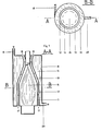
- the boiler shown in FIG. 1 comprises an electric heating resistor 5 constituting a source of radiant energy at high temperature, which is surrounded by a first cylindrical wall 1 constituting a primary, radiating, coaxial partition formed of a material capable of supporting the high temperature of the radiant heat produced by the heating resistor 5.
- This primary, radiant partition has internal and external faces which are blackened, so that it can act as a black body capable of absorbing this radiant heat on its front face , internal, to heat up as well, and to emit secondary radiation in the visible spectrum.
- These two coaxial partitions 1 and 2 are radially spaced and delimit between them an annular passage forming an intermediate channel 3 which is provided with an inlet opening 7 and an outlet opening 8 communicating with the outside of the device and serving to allow free air circulation in this channel 3, as indicated by arrows in FIG. 1.
- the water tank 4 of the boiler described is delimited by an external insulating wall 6, closed at its two ends, and provided with a cold water inlet 9 and a hot water outlet 10.
- the coaxial partitions 1 and 2 thus delimit the intermediate channel 3 which separates the source of energy at high temperature, constituted by the heating resistor 5, from the water to be heated in the tank 4.
- the boiler shown in FIG. 3 comprises an oil burner which has a flame 15, constitutes a source of radiant energy at high temperature, and is arranged axially in a combustion chamber delimited by a cylindrical wall 11 constituting a primary, radiating partition. , coaxial formed of a material capable of withstanding the high temperature of the flame 15 of the burner.
- This primary, radiant partition 11 has blackened internal and external faces, so that it can act as a black body capable of absorbing on its blackened internal surface the radiant heat emitted by the flame 15, thus heating up, and reemitting radially towards the exterior, from its blackened external surface, secondary radiation in the visible spectrum.
- This first wall 11 constituting a primary, radiating partition used to intercept and re-emit the radiation produced by the flame 15, is surrounded by a second cylindrical wall 12 which constitutes a secondary, coaxial partition formed of a heat conducting material, and which serves to the exchange of heat with the water to be heated contained in a tank 14.
- the two coaxial walls 11 and 12 are spaced radially from each other, serve to delimit between them a vertical annular passage forming an intermediate channel 13 which is provided at its lower end with an air inlet 17 and, at its upper end with an air outlet 18, and allows free circulation of air along this channel 13, as indicated by arrows in FIG. 3.
- the tank 14 of this boiler is delimited by an external insulating wall 16 closed at its two ends, and provided with a tangential cold water inlet 19 and a radial hot water outlet 20 .
- the coaxial walls 11 and 12 thus delimit the intermediate channel 13 which separates the flame 15 from the burner, constituting the source of energy at high temperature, from the water to be heated.
- the heating device according to FIGS. 4 and 5 constitutes a variant similar to that already described according to FIGS. 1 and 2.
- the identical elements thus have the same reference numbers in FIGS. 1.2 and 5.6, and will only be briefly described here.
- the heating device is provided with an electrical resistance composed of a plurality of electrical heating spirals 25, each mounted on a porcelain support and housed respectively in corresponding longitudinal grooves formed at the periphery of a body refractory 22.
- This body 22 is heated to high temperature by these spirals 25 and has an external wall 21, constituting a primary wall used to emit thermal radiation in the visible spectrum and to delimit one side of the intermediate channel 3 for the free circulation of air using the air inlet 7 and outlet 8 openings communicating with the outside of the heating device.
- the intermediate channel 3 is also delimited by a secondary wall 2 whose internal surface receives, through this channel 3, the thermal radiation emitted in the visible spectrum by the primary wall 21, while its external surface is in contact with water to be heated in the tank 4, provided with an external insulating wall 6 and inlet 9 and outlet 10 openings.
- the radiation heating device according to the invention can also be advantageously used for heating water or any other suitable medium, therefore various fluids, liquids or gases, or any solid medium, intended for indirect heating by transmitted thermal radiation. through said intermediate air circulation channel.
- said intermediate air circulation channel comprising in particular said primary, radiant wall associated with said intermediate channel of free air circulation, it becomes possible to carry this wall pri mayor, radiating at a very high temperature allowing it to emit thermal radiation in the visible spectrum, to avoid at the same time any harmful overheating, or indeed undesirable cooling, and thus to ensure prolonged indirect heating by high radiation temperature with high efficiency.
Landscapes
- Engineering & Computer Science (AREA)
- Physics & Mathematics (AREA)
- Thermal Sciences (AREA)
- Chemical & Material Sciences (AREA)
- Combustion & Propulsion (AREA)
- Mechanical Engineering (AREA)
- General Engineering & Computer Science (AREA)
- Heat-Pump Type And Storage Water Heaters (AREA)
Applications Claiming Priority (2)
| Application Number | Priority Date | Filing Date | Title |
|---|---|---|---|
| CH110685 | 1985-03-12 | ||
| CH1106/85 | 1985-03-12 |
Publications (2)
| Publication Number | Publication Date |
|---|---|
| EP0194975A2 true EP0194975A2 (de) | 1986-09-17 |
| EP0194975A3 EP0194975A3 (de) | 1988-07-13 |
Family
ID=4202629
Family Applications (1)
| Application Number | Title | Priority Date | Filing Date |
|---|---|---|---|
| EP86810126A Withdrawn EP0194975A3 (de) | 1985-03-12 | 1986-03-12 | Strahlungsheizeinrichtung |
Country Status (1)
| Country | Link |
|---|---|
| EP (1) | EP0194975A3 (de) |
Cited By (7)
| Publication number | Priority date | Publication date | Assignee | Title |
|---|---|---|---|---|
| EP0262263A1 (de) * | 1985-04-04 | 1988-04-06 | van Heel, Joannes Marie | Lufterhitzer |
| EP0374878A3 (de) * | 1988-12-23 | 1991-02-20 | Atwood Industries Inc. | Gasheizgerät zur Warmwasserbereitung und zur Raumheizung |
| US5054108A (en) * | 1987-03-30 | 1991-10-01 | Arnold Gustin | Heater and method for deionized water and other liquids |
| EP0877208A3 (de) * | 1997-05-07 | 2000-07-05 | Dietrich Schröck | Strahlungswärme-Raumheizsystem |
| WO2008043573A1 (en) * | 2006-10-13 | 2008-04-17 | Willis Heating And Plumbing Co Ltd | Water heating apparatus and system |
| WO2015117219A1 (en) * | 2014-02-07 | 2015-08-13 | Sylvain Laberge | Baseboard for use in preheating water |
| WO2019025636A1 (en) * | 2017-08-04 | 2019-02-07 | Dometic Sweden Ab | HEAT TRANSFER UNIT, UNIT AND HEATING APPARATUS FOR RECREATIONAL VEHICLES, AND RECREATIONAL VEHICLES |
Family Cites Families (3)
| Publication number | Priority date | Publication date | Assignee | Title |
|---|---|---|---|---|
| US2084287A (en) * | 1935-08-29 | 1937-06-15 | Handley Brown Heater Company | Apparatus for heating liquids with fluid fuel |
| US2377785A (en) * | 1943-08-25 | 1945-06-05 | Walter E Hudson | Electric furnace water heater |
| DE1295163B (de) * | 1964-04-04 | 1969-05-14 | Ettling Hermann | Raumlufterhitzer mit Brauchwasserbereiter |
-
1986
- 1986-03-12 EP EP86810126A patent/EP0194975A3/de not_active Withdrawn
Cited By (7)
| Publication number | Priority date | Publication date | Assignee | Title |
|---|---|---|---|---|
| EP0262263A1 (de) * | 1985-04-04 | 1988-04-06 | van Heel, Joannes Marie | Lufterhitzer |
| US5054108A (en) * | 1987-03-30 | 1991-10-01 | Arnold Gustin | Heater and method for deionized water and other liquids |
| EP0374878A3 (de) * | 1988-12-23 | 1991-02-20 | Atwood Industries Inc. | Gasheizgerät zur Warmwasserbereitung und zur Raumheizung |
| EP0877208A3 (de) * | 1997-05-07 | 2000-07-05 | Dietrich Schröck | Strahlungswärme-Raumheizsystem |
| WO2008043573A1 (en) * | 2006-10-13 | 2008-04-17 | Willis Heating And Plumbing Co Ltd | Water heating apparatus and system |
| WO2015117219A1 (en) * | 2014-02-07 | 2015-08-13 | Sylvain Laberge | Baseboard for use in preheating water |
| WO2019025636A1 (en) * | 2017-08-04 | 2019-02-07 | Dometic Sweden Ab | HEAT TRANSFER UNIT, UNIT AND HEATING APPARATUS FOR RECREATIONAL VEHICLES, AND RECREATIONAL VEHICLES |
Also Published As
| Publication number | Publication date |
|---|---|
| EP0194975A3 (de) | 1988-07-13 |
Similar Documents
| Publication | Publication Date | Title |
|---|---|---|
| EP0520913B1 (de) | Heizung mit katalytischem Brenner | |
| EP0194975A2 (de) | Strahlungsheizeinrichtung | |
| EP3274637B1 (de) | Kessel und tür zu diesem kessel | |
| FR2945107A1 (fr) | Radiateur electrique a fluide caloporteur forme d'elements modulaires moules | |
| EP0429371B1 (de) | Heizkörper für Kessel für Wärmeträgerflüssigkeit | |
| EP3879186B1 (de) | Ionen-heizkessel | |
| FR2514474A1 (fr) | Dispositif de chauffage d'un bain d'huile | |
| FR3041159A1 (fr) | Module et dispositif thermo electriques, notamment destines a generer un courant electrique dans un vehicule automobile | |
| EP4600561A1 (de) | Flüssigkeitsheizkörper mit externem heizkörper | |
| FR2997787A1 (fr) | Generateur nucleaire a radioisotope | |
| WO2017046492A1 (fr) | Dispositif thermo électrique, notamment destiné a générer un courant électrique dans un véhicule automobile | |
| WO2017046488A1 (fr) | Dispositif thermo électrique, notamment destiné a générer un courant électrique dans un véhicule automobile | |
| CA2064967A1 (fr) | Chaudiere de chauffage | |
| FR2468852A1 (fr) | Chaudiere, notamment pour installations de chauffage domestique | |
| WO2017046489A1 (fr) | Dispositif thermo électriques, notamment destinés a générer un courant électrique dans un véhicule automobile | |
| FR2559243A1 (fr) | Chaudiere de chauffage d'un fluide caloporteur | |
| EP0487434B1 (de) | Wärmetauscher für Gaskessel, Herstellungsverfahren dafür und Kessel mit einem solchen Wärmetauscher | |
| FR1402699A (fr) | Générateur de chaleur notamment pour la production d'eau chaude | |
| EP0062573A1 (de) | Erhitzer für festen Brennstoff | |
| EP0189708A1 (de) | Gaswassererhitzer | |
| FR2513745A1 (fr) | Chauffe-eau a accumulation et a gaz | |
| FR2800856A1 (fr) | Chaudiere de chauffage du type vertical | |
| FR3041154A1 (fr) | Module et dispositif thermo electriques, notamment destines a generer un courant electrique dans un vehicule automobile | |
| BE634201A (de) | ||
| FR2751735A1 (fr) | Chaudiere de chauffage central a bruleur fioul |
Legal Events
| Date | Code | Title | Description |
|---|---|---|---|
| PUAI | Public reference made under article 153(3) epc to a published international application that has entered the european phase |
Free format text: ORIGINAL CODE: 0009012 |
|
| AK | Designated contracting states |
Kind code of ref document: A2 Designated state(s): AT BE CH DE FR GB IT LI LU NL SE |
|
| PUAL | Search report despatched |
Free format text: ORIGINAL CODE: 0009013 |
|
| AK | Designated contracting states |
Kind code of ref document: A3 Designated state(s): AT BE CH DE FR GB IT LI LU NL SE |
|
| 17P | Request for examination filed |
Effective date: 19890111 |
|
| 17Q | First examination report despatched |
Effective date: 19891201 |
|
| STAA | Information on the status of an ep patent application or granted ep patent |
Free format text: STATUS: THE APPLICATION IS DEEMED TO BE WITHDRAWN |
|
| 18D | Application deemed to be withdrawn |
Effective date: 19900412 |
|
| RIN1 | Information on inventor provided before grant (corrected) |
Inventor name: GROSJEAN, MAURICE |