EP0195115A2 - Dichtring - Google Patents
Dichtring Download PDFInfo
- Publication number
- EP0195115A2 EP0195115A2 EP85109911A EP85109911A EP0195115A2 EP 0195115 A2 EP0195115 A2 EP 0195115A2 EP 85109911 A EP85109911 A EP 85109911A EP 85109911 A EP85109911 A EP 85109911A EP 0195115 A2 EP0195115 A2 EP 0195115A2
- Authority
- EP
- European Patent Office
- Prior art keywords
- sealing
- sealing lip
- machine part
- relatively moving
- movement
- Prior art date
- Legal status (The legal status is an assumption and is not a legal conclusion. Google has not performed a legal analysis and makes no representation as to the accuracy of the status listed.)
- Granted
Links
Images
Classifications
-
- F—MECHANICAL ENGINEERING; LIGHTING; HEATING; WEAPONS; BLASTING
- F16—ENGINEERING ELEMENTS AND UNITS; GENERAL MEASURES FOR PRODUCING AND MAINTAINING EFFECTIVE FUNCTIONING OF MACHINES OR INSTALLATIONS; THERMAL INSULATION IN GENERAL
- F16J—PISTONS; CYLINDERS; SEALINGS
- F16J15/00—Sealings
- F16J15/56—Other sealings for reciprocating rods
-
- F—MECHANICAL ENGINEERING; LIGHTING; HEATING; WEAPONS; BLASTING
- F16—ENGINEERING ELEMENTS AND UNITS; GENERAL MEASURES FOR PRODUCING AND MAINTAINING EFFECTIVE FUNCTIONING OF MACHINES OR INSTALLATIONS; THERMAL INSULATION IN GENERAL
- F16J—PISTONS; CYLINDERS; SEALINGS
- F16J15/00—Sealings
- F16J15/16—Sealings between relatively-moving surfaces
- F16J15/32—Sealings between relatively-moving surfaces with elastic sealings, e.g. O-rings
- F16J15/3204—Sealings between relatively-moving surfaces with elastic sealings, e.g. O-rings with at least one lip
Definitions
- the invention relates to a sealing ring for a reciprocating machine part, comprising a sealing element made of polymer material, which is provided with a sealing lip, in which the sealing lip is pressed elastically against the relatively moving machine part and in which the sealing lip of the direction of movement of the relatively moving machine part is assigned obliquely.
- GB-PS 1 078 586 refers to a sealing ring of the aforementioned type. It serves to seal the valve stem of an internal combustion engine, and the sealing lip which is diagonally associated with the direction of movement of the valve stem is coiled like a thread. It penetrates the sealing element along its entire axial length. Sealed medium, in the present case lubricating oil, is able to overcome the sealing element through the spaces between the individual turns and is thus available in a metered amount for the lubrication of the valve stem. This effect is desirable in the present case, but causes an impairment of the sealing result achieved in absolute terms. The sealing ring is therefore not suitable for applications in which an absolute sealing result is sought. Foreign substances from the sealed medium that are embedded in the spaces between the individual turns can further impair the sealing effect and cause severe wear in the area of the dynamic sealing zone.
- the invention has for its object to show a sealing ring for a reciprocating machine part, which ensures the achievement of an excellent sealing result and which is largely insensitive to foreign substances contained in the sealed medium.
- the sealing lip of the sealing ring according to the invention is obliquely assigned to the direction of movement of the relatively moving machine part in all areas, which necessitates a lateral displacement of the stripped medium while the stripping process is being carried out. This results in an intensification of the mixing of the stripped volume in itself. It results from the mutual superimposition of the circulation of the stripped volume in the direction of movement with a corresponding circulation in the circumferential direction. Excellent lubrication of the dynamic sealing zone is thereby always guaranteed, the formation of caking in this critical area is effectively prevented.
- the sealing lip can have a constant inclination within each area, which, in addition to a straight course, requires an abrupt change in direction at each transition point to the adjacent area.
- the sealing lip has a changing inclination within each area and if it connects adjacent areas without a sudden change in inclination.
- the resulting sealing tape has a sinusoidal curve.
- the sealing ring according to the invention is preferably used in the sealing of piston rods.
- the pressing direction of the sealing lip is directed inwards.
- Versions in which the sealing lip has an outward pressing direction are suitable for sealing pistons.
- the shape of the sealing lip is thus in any case adapted to the shape of the machine part to be sealed, and in individual cases there may also be deviations from the usual, rotationally symmetrical shape.
- An oval profile, a polygonal profile or a cross-section of the relatively moving machine part which is shaped by a mixture of different profiles is readily possible, for example a cross-section in which flat surfaces, slightly and strongly curved surfaces are connected to one another.
- appropriate training can transmit torsional forces over the connection zone of the sealed parts, which is of great advantage for certain applications. A good sealing result with a long service life is guaranteed in any case.
- the sealing ring In cases where the sealing ring is intended for use in sealing a relatively moving machine part with at least one plane surface extending parallel to the direction of movement, it has proven to be advantageous if the section of the sealing lip sealing the plane surface is inclined continuously in the same direction .
- the sealed medium stripped from the flat surface is accumulated to a particularly large extent by appropriate training, which makes it much easier to remove foreign bodies from the area of the dynamic sealing zone.
- the sealing lip in its entirety, however, a relatively large axial extension, which is not always tolerable b ar.
- the section of the sealing lip which seals the flat surface has two adjacent regions of an opposite direction of inclination. These are appropriately inclined so that the sealing lip projects into the sealed space in the zone of mutual connection of the two areas.
- a ship's bow-like design of the sealing lip in the area of the flat surface has proven to be expedient, the two adjacent areas of the sealing lip advantageously being formed so as to merge into one another, ie with a rounded course of the sealing lip.
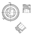
- the sealing ring has a profile of an essentially X-shaped shape, which is sealed on the outside by axially projecting e , statically acting sealing lips from the cylindrical housing bore, not shown, and on the inside by axially projecting, dynamically acting sealing lips from the rod to be sealed.
- the statically acting sealing lips are characterized over the entire circumference by a constant profile, which is widened only at the point of a projection acting as an anti-rotation device.
- the dynamically acting sealing lips are accordingly increasingly thickened in the direction of the central part of each sealing surface of the rod to be sealed and bulged inwards.
- the statically acting sealing lips are accordingly of circular shape, the dynamically acting sealing lips are adapted approximately to the square profile of the rod to be sealed. They are continuously merged into one another, and the inward-facing curvature arranged in the middle region experiences an axial displacement due to the introduction of the rod to be sealed, which leads to an inclined position of the sealing lip with respect to the direction of movement of the rod to be sealed.
- the inclination with respect to the direction of movement resulting from the inclined position of the sealing lip differs in different zones and has increasingly larger values in the direction of the mutual delimitation of the sealed plane surfaces than in the central area.
- the medium volume stripped from the sealed rod under operating conditions experiences an intensive circulation leading out of the area of each flat surface, which makes it extremely difficult for foreign bodies to penetrate the sealing gap in this critical area.
- the inclination of the sealing lip is varied symmetrically over the width of each sealing surface of the sealed rod.
- the pressure on the rod to be sealed is based on the inherent elasticity of the elastomeric material used. It is completely balanced by increasing the cross section of the dynamic sealing lips towards the center of each sealed surface. Therefore, changes in the sealing result are not to be expected even after long use.
- the elastomeric material used is an elastomeric polyurethane with a Shore A hardness of 80-95. The use of rubber is of course also possible.
- the sealing ring according to the invention enables a significant improvement in the performance properties achieved to date. It is relatively simple and accordingly inexpensive to manufacture and is suitable for both the sealing of liquid and the sealing of gaseous substances.
Landscapes
- Engineering & Computer Science (AREA)
- General Engineering & Computer Science (AREA)
- Mechanical Engineering (AREA)
- Sealing With Elastic Sealing Lips (AREA)
- Glass Compositions (AREA)
- Sealing Devices (AREA)
- Materials For Medical Uses (AREA)
- Pharmaceuticals Containing Other Organic And Inorganic Compounds (AREA)
- Hand Tools For Fitting Together And Separating, Or Other Hand Tools (AREA)
- Automatic Assembly (AREA)
- Auxiliary Devices For And Details Of Packaging Control (AREA)
Abstract
Description
- Die Erfindung betrifft einen Dichtring für ein hin- und hergehendes Maschinenteil, umfassend ein Dichtelement aus polymerem Werkstoff, das mit einer Dichtlippe versehen ist, bei dem die Dichtlippe elastisch an das relativ bewegte Maschinenteil angepreßt ist und bei dem die Dichtlippe der Bewegungsrichtung des relativ bewegten Maschinenteiles schräg zugeordnet ist.
- Auf einen Dichtring der vorgenannten Art nimmt die GB-PS 1 078 586 Bezug. Er dient der Abdichtung des Ventilschaftes eines Verbrennungsmotors, und die der Bewegungsrichtung des Ventilschaftes schräg zugeordnete Dichtlippe ist ähnlich einem Gewindegang gewendelt. Sie durchdringt das Dichtelement auf seiner gesamten axialen Länge. Abgedichtetes Medium, im vorliegenden Falle Schmieröl, vermag durch die Zwischenräume der einzelnen Windungen hindurch das Dichtelement zu überwinden und steht so in dosierter Menge für die Schmierung des Ventilschaftes zur Verfügung. Dieser Effekt ist im vorliegenden Falle erwünscht, bedingt indessen eine Beeinträchtigung des in absoluter Hinsicht erzielten Abdichtungsergebnisses. Der Dichtring ist daher für Anwendungsfälle, in denen ein absolutes Abdichtungsergebnis angestrebt wird, nicht brauchbar. In die Zwischenräume zwischen den einzelnen Windungen eingelagerte Fremdstoffe aus dem abgedichteten Medium können darüber hinaus die Abdichtwirkung noch weiter beeinträchtigen und starken Verschleiß im Bereich der dynamischen Abdichtungszone verursachen.
- Der Erfindung liegt die Aufgabe zugrunde, einen Dichtring für ein hin- und hergehendes Maschinenteil zu zeigen, der die Erzielung eines ausgezeichneten Abdichtungsergebnisses gewährleistet und der weitgehend unempfindlich ist im Hinblick auf in dem abgedichteten Medium enthaltene Fremdstoffe.
- Diese Aufgabe wird erfindungsgemäß bei einem Dichtring der eingangs genannten Art dadurch gelöst, daß die sich aus der schrägen Zuordnung der Dichtlippe zu der Bewegungsrichtung des relativ bewegten Maschinenteiles ergebende Neigung in auf dem Umfang der Dichtlippe verteilten Bereichen eine entgegengesetzte Richtung aufweist und daß die einzelnen Bereiche unter Bildung eines das relativ bewegte Maschinenteil berührenden, axial undurchlässigen Dichtbandes lückenlos ineinander übergehend ausgebildet sind.
- Die Dichtlippe des erfindungsgemäßen Dichtringes ist der Bewegungsrichtung des relativ bewegten Maschinenteiles in allen Bereichen schräg zugeordnet, was eine seitliche Verlagerung des abgestreiften Mediums während der Durchführung des Abstreifvorganges bedingt. Eine Intensivierung der Durchmischung des abgestreiften Volumens in sich selbst ist hiervon die Folge. Sie ergibt sich aus der gegenseitigen Überlagerung der Umwälzung des abgestreiften Volumens in Bewegungsrichtung mit einer entsprechenden Umwälzung in Umfangsrichtung. Eine ausgezeichnete Schmierung der dynamischen Abdichtungszone ist hierdurch stets gewährleistet, die Entstehung von Anbackungen in diesem kritischen Bereich wird wirksam verhindert.
- Die Dichtlippe kann innerhalb eines jeden Bereiches eine gleichbleibende Neigung aufweisen, was neben einem geradlinigen Verlauf eine sprunghafte Richtungsänderung an einer jeden Übergangsstelle zu dem benachbarten Bereich bedingt.
- Entsprechende Ausführungen lassen sich besonders kostengünstig erzeugen.
- Im Hinblick auf die Erzielung einer besonders guten Dauerhaftigkeit hat es sich demqegenüber als vorteilhafter bewährt, wenn die Dichtlippe innerhalb eines jeden Bereiches eine sich verändernde Neigung aufweist, und wenn sie benachbarte Bereiche ohne sprunghafte Neigungsänderung verbindet. Das sich in diesem Falle ergebende Dichtband hat einen sinuskurvenähnlich ausgebildeten Verlauf.
- Die durch die Neigung der Dichtlippe verursachte Umwälzung des abgestreiften Mediums in sich selbst erfährt mit zunehmender Steilheit des Neigungswinkels eine Intensivierung, was an sich von Vorteil ist. Steile Neigungswinkel machen es indessen unter Berücksichtigung üblicher Baugrößen zunehmend schwieriger, eine ausreichend gleichmäßige Anpressung der Dichtlippe an das relativ bewegte Maschinenteil zu gewährleisten. Ausführungen, bei denen die Dichtlippe einer sich quer zu der Bewegungsrichtung erstreckenden Ebene unter einem Winkel von maximal 5°, vorzugsweise von maximal 3° zugeordnet ist, werden aus diesem Grunde bevorzugt.
- Der erfindungsgemäße Dichtring gelangt bevorzugt zur Anwendung bei der Abdichtung von Kolbenstangen. Die Anpreßrichtung der Dichtlippe ist in diesem Falle nach innen gerichtet.
- Ausführungen, bei denen die Dichtlippe eine nach außen gerichtete Anpreßrichtung aufweist, eignen sich für die Abdichtung von Kolben.
- Die Gestalt der Dichtlippe ist somit in jedem Falle an die Gestalt des abzudichtenden Maschinenteiles angepaßt, wobei sich im Einzelfalle auch Abweichungen von der üblichen, rotationssymmetrischen Gestalt ergeben können. Ein ovales Profil, ein polygonformiges Profil oder ein durch eine Mischform aus verschiedenen Profilen geprägter Querschnitt des relativ bewegten Maschintenteiles ist ohne weiteres möglich, beispielsweise ein Querschnitt, bei dem ebene Flächen, leicht und stark gewölbte Flächen ineinander übergehend verbunden sind. Neben einer großen Steifigkeit bei geringem Gewicht lassen sich durch eine entsprechende Ausbildung Drehkräfte über die Verbindungszone der abgedichteten Teile übertragen, was für bestimmte Anwendungen von großem Vorteil ist. Ein gutes Abdichtungsergebnis bei langer Gebrauchsdauer ist dennoch in jedem Falle gewährleistet.
- In Fällen, in denen der Dichtring zur Verwendung bei der Abdichtung eines relativ bewegten Maschinenteiles mit wenigstens einer sich parallel zu der Bewegungsrichtung erstreckenden Planfläche vorgesehen ist, hat es sich als vorteilhaft bewährt, wenn der die Planfläche abdichtende Abschnitt der Dichtlippe durchgehend im gleichen Richtungssinne geneigt ist. Das von der Planfläche abgestreifte, abgedichtete Medium wird durch eine entsprechende Ausbildung in besonders großem Maße kumuliert, was es stark erleichtert, Fremdkörper aus dem Bereich der dynamischen Abdichtungszone zu entfernen.
- Bei einer entsprechenden Ausführung eines Dichtringes hat die Dichtlippe in ihrer Gesamtheit jedoch eine relativ große axiale Erstreckung, was nicht immer tolerier- bar ist. Im Hinblick auf die Erzielung einer möglichst kleinen axialen Baulänge hat es sich daher als vorteilhaft bewährt, wenn der die Planfläche abdichtende Abschnitt der Dichtlippe zwei benachbarte Bereiche einer entgegengesetzten Neigungsrichtung aufweist. Diese sind zweckmäßig so geneigt, daß die Dichtlippe in der Zone der gegenseitigen Verbindung beider Bereiche in den abgedichteten Raum vorspringt. Eine schiffsbugähnliche Ausbildung der Dichtlippe im Bereich der Planfläche hat sich als zweckmäßig erwiesen, wobei die beiden benachbarten Bereiche der Dichtlippe zweckmäßig gleichmäßig ineinander übergehend ausgebildet sind, d.h. mit einem gerundeten Verlauf der Dichtlippe.
- Eine beispielhafte Ausführung des erfindungsgemäß vorgeschlagenen Dichtringes ist in der in der Anlage beigefügten Zeichnung dargestellt. Er wird nachfolgend näher erläutert:
- Der gezeigte Dichtring ist für eine Festlegung in einer zylindrischen Bohrung bestimmt sowie für die dynamische Abdichtung einer sich in der Bohrung axial hin- und herbewegenden Stange von quadratischem Profil.
- Der Dichtring weist ein Profil von im wesentlichen X-förmiger Gestalt auf, das außenseitig durch axial vorspringende, statisch wirkende Dichtlippen gegenüber der nicht dargestellten, zylindrischen Gehäusebohrung abgedichtet ist und innenseitig durch axial vorspringende, dynamisch wirkende Dichtlippen gegenüber der abzudichtenden Stange. Die statisch wirkenden Dichtlippen sind auf dem gesamten Umfang durch ein gleichbleibendes Profil gekennzeichnet, das lediglich an der Stelle eines als Verdrehsicherung wirkenden Vorsprunges eine Aufweitung erfährt.
- Die dynamisch wirkenden Dichtlippen sind demgeqenüber in Richtung des mittleren Teiles einer jeden Dichtfläche der abzudichtenden Stange zunehmend verdickt und einwärts vorgewölbt.
- Die statisch wirkenden Dichtlippen sind dementsprechend von kreisförmiger Gestalt, die dynamisch wirkenden Dichtlippen in etwa an das quadratische Profil der abzudichtenden Stange angepaßt. Sie sind kontinuierlich ineinander übergehend ausgebildet, und die im mittleren Bereich angeordnete, einwärts gerichtete Wölbung erfährt durch die Einführung der abzudichtenden Stange eine axiale Verlagerung, was zu einer Schrägstellung der Dichtlippe in bezug auf die Bewegungsrichtung der abzudichtenden Stange führt. Die sich durch die Schrägstellung der Dichtlippe ergebende Neigung in bezug auf die Bewegungsrichtung ist in verschiedenen Zonen unterschiedlich und weist in Richtung der beiderseitigen Begrenzungen der abgedichteten Planflächen zunehmend größere Werte auf als im mittleren Bereich. Das unter Betriebsbedingungen von der abgedichteten Stange abgestreifte Mediumsvolumen erfährt hierdurch eine intensive, aus dem Bereich einer jeden Planfläche herausführende Umwälzung, was ein Eindringen von Fremdkörpern in den Dichtspalt in diesem kritischen Bereich außerordentlich erschwert.
- Die einzelnen Volumina treffen anschließend im Bereich der Ecken des Profils der abgedichteten Stange massiert aufeinander, was neben der eigentlichen Kumulierung zu starker Walkbewegung führt. Fremdkörper können daher auch in diesem Bereich nicht in die kritische Zone zwischen der Dichtlippe und der abgedichteten Stange eindringen. Die ausgezeichneten Gebrauchseigenschaften des erfindungsgemäßen Dichtringes dürften vor allem auf diese vorstehend beschriebenen Effekte zurückzuführen sein.
- Die Schrägstellung der Dichtlippe ist über die Breite einer jeden Dichtfläche der abgedichteten Stange symmetrisch variiert. Die Anpressung an die abzudichtende Stange beruht auf der Eigenelastizität des verwendeten elastomeren Werkstoffes. Sie ist durch die Vergrößerung des Querschnittes der dynamisch wirkenden Dichtlippen in Richtung der Mitte einer jeden abgedichteten Fläche vollkommen ausgeglichen. Auch nach langem Gebrauch sind daher Veränderungen des Abdichtungsergebnisses nicht zu erwarten. Bei dem verwendeten elastomeren Werkstoff handelt es sich um ein elastomeres Polyurethan der Härte Shore A von 80 - 95. Die Verwendung von Gummi ist natürlich ebenfalls möglich.
- Der erfindungsgemäße Dichtring ermöglicht eine wesentliche Verbesserung der bisher erzielten Gebrauchseigenschaften. Er ist relativ einfach und dementsprechend kostenqünstig herstellbar und eignet sich sowohl für die Abdichtung flüssiger als auch für die Abdichtung gasförmiger Stoffe.
Claims (8)
Priority Applications (1)
| Application Number | Priority Date | Filing Date | Title |
|---|---|---|---|
| AT85109911T ATE56797T1 (de) | 1985-03-19 | 1985-08-07 | Dichtring. |
Applications Claiming Priority (2)
| Application Number | Priority Date | Filing Date | Title |
|---|---|---|---|
| DE3509840 | 1985-03-19 | ||
| DE3509840A DE3509840C2 (de) | 1985-03-19 | 1985-03-19 | Dichtring |
Publications (3)
| Publication Number | Publication Date |
|---|---|
| EP0195115A2 true EP0195115A2 (de) | 1986-09-24 |
| EP0195115A3 EP0195115A3 (en) | 1987-11-19 |
| EP0195115B1 EP0195115B1 (de) | 1990-09-19 |
Family
ID=6265659
Family Applications (1)
| Application Number | Title | Priority Date | Filing Date |
|---|---|---|---|
| EP85109911A Expired - Lifetime EP0195115B1 (de) | 1985-03-19 | 1985-08-07 | Dichtring |
Country Status (5)
| Country | Link |
|---|---|
| EP (1) | EP0195115B1 (de) |
| AT (1) | ATE56797T1 (de) |
| DE (2) | DE3509840C2 (de) |
| ES (1) | ES288992Y (de) |
| NO (1) | NO171577C (de) |
Cited By (3)
| Publication number | Priority date | Publication date | Assignee | Title |
|---|---|---|---|---|
| EP0561038A1 (de) * | 1992-03-16 | 1993-09-22 | Firma Carl Freudenberg | Dichtung für ein hin- und hergehendes Maschinenteil |
| EP0965779A3 (de) * | 1998-06-20 | 2000-09-06 | Festo AG & Co | Dichtungsring |
| EP2360089A1 (de) * | 2010-02-23 | 2011-08-24 | Single Buoy Moorings Inc. | Flüssigkeitsverwirbeler für die Flüssigkeitsübertragung über eine Drehschnittstelle |
Families Citing this family (3)
| Publication number | Priority date | Publication date | Assignee | Title |
|---|---|---|---|---|
| DE4139919C2 (de) * | 1991-12-04 | 1994-01-20 | Freudenberg Carl Fa | Dichtung für einen hin- und hergehenden Körper |
| IT201800008012A1 (it) | 2018-08-09 | 2020-02-09 | Truma Geraetetechnik Gmbh & Co Kg | Dispositivo di sicurezza per un dispositivo di conduzione del gas |
| IT201800008014A1 (it) | 2018-08-09 | 2020-02-09 | Truma Geraetetechnik Gmbh & Co Kg | Regolatore di pressione di gas |
Family Cites Families (4)
| Publication number | Priority date | Publication date | Assignee | Title |
|---|---|---|---|---|
| SE320226B (de) * | 1965-06-14 | 1970-02-02 | Dana Corp | |
| DE1953846U (de) * | 1966-10-10 | 1967-01-19 | Alois Ferch | Schaftabdichtungsvorrichtung. |
| DE3039534A1 (de) * | 1980-10-20 | 1982-04-29 | Fa. Carl Freudenberg, 6940 Weinheim | Selbstarretierender dicht-abstreifring |
| US4475738A (en) * | 1982-04-15 | 1984-10-09 | Hilliard Lyons Patent Management Inc. | Dynamic seal arrangement with X-shaped seal |
-
1985
- 1985-03-19 DE DE3509840A patent/DE3509840C2/de not_active Expired
- 1985-08-07 DE DE8585109911T patent/DE3579809D1/de not_active Expired - Lifetime
- 1985-08-07 AT AT85109911T patent/ATE56797T1/de not_active IP Right Cessation
- 1985-08-07 EP EP85109911A patent/EP0195115B1/de not_active Expired - Lifetime
- 1985-09-09 NO NO853515A patent/NO171577C/no unknown
- 1985-09-11 ES ES1985288992U patent/ES288992Y/es not_active Expired
Cited By (4)
| Publication number | Priority date | Publication date | Assignee | Title |
|---|---|---|---|---|
| EP0561038A1 (de) * | 1992-03-16 | 1993-09-22 | Firma Carl Freudenberg | Dichtung für ein hin- und hergehendes Maschinenteil |
| EP0965779A3 (de) * | 1998-06-20 | 2000-09-06 | Festo AG & Co | Dichtungsring |
| EP2360089A1 (de) * | 2010-02-23 | 2011-08-24 | Single Buoy Moorings Inc. | Flüssigkeitsverwirbeler für die Flüssigkeitsübertragung über eine Drehschnittstelle |
| WO2011103936A1 (en) * | 2010-02-23 | 2011-09-01 | Single Buoy Moorings, Inc. | A fluid swivel for allowing fluid transfer across a rotary interface |
Also Published As
| Publication number | Publication date |
|---|---|
| EP0195115A3 (en) | 1987-11-19 |
| NO171577C (no) | 1993-03-31 |
| NO853515L (no) | 1986-09-22 |
| ES288992U (es) | 1986-01-16 |
| DE3579809D1 (de) | 1990-10-25 |
| NO171577B (no) | 1992-12-21 |
| DE3509840C2 (de) | 1987-05-14 |
| ATE56797T1 (de) | 1990-10-15 |
| DE3509840A1 (de) | 1986-10-02 |
| ES288992Y (es) | 1986-10-16 |
| EP0195115B1 (de) | 1990-09-19 |
Similar Documents
| Publication | Publication Date | Title |
|---|---|---|
| EP0033964B1 (de) | Radialwellendichtring | |
| DE69929713T2 (de) | Hydrodynamische dichtung und verfahren zur herstellung | |
| DE3833042A1 (de) | Wellendichtung | |
| EP2988035B1 (de) | Dichtring und dessen verwendung | |
| DE1956165B2 (de) | Radialhppendichtnng fur Wellen | |
| DE2949839C2 (de) | Dichtring | |
| DE19739472A1 (de) | Dichtungsanordnung | |
| CH660407A5 (de) | Dichtring fuer kolbenstangen. | |
| EP0431325A1 (de) | Kolben- oder Stangendichtung | |
| DE10102161B4 (de) | Ringförmige Dichtung | |
| DE69105107T2 (de) | Dichtungsringträger für einen taumelkolben. | |
| DE3830706A1 (de) | Wellendichtung | |
| DE69918910T3 (de) | Ringförmige Dichtung, insbesondere für eine Antriebswelle eines Kraftfahrzeuges | |
| DE2305826A1 (de) | Dichtungsringanordnung | |
| DE3509840C2 (de) | Dichtring | |
| EP0798498A1 (de) | Radialwellendichtring mit drehrichtungsunabhängiger Förderwirkung | |
| DE3501066C2 (de) | ||
| EP0434908B1 (de) | Kolben- oder Stangendichtung | |
| DE3501334C1 (de) | Dichtung | |
| EP0338130A2 (de) | Dichtung für einen Teleskopdämpfer | |
| DE3706940C1 (de) | Kolben fuer Brennkraftmaschinen | |
| EP0544984B1 (de) | Dichtung an einem hin- und hergehenden Körper | |
| DE3320855C1 (de) | Dichtung | |
| DE2614263A1 (de) | Dynamisch nachstellbare dichtungs- und fuehrungsvorrichtung | |
| DE19936462B4 (de) | Abstreifring |
Legal Events
| Date | Code | Title | Description |
|---|---|---|---|
| PUAI | Public reference made under article 153(3) epc to a published international application that has entered the european phase |
Free format text: ORIGINAL CODE: 0009012 |
|
| AK | Designated contracting states |
Kind code of ref document: A2 Designated state(s): AT BE CH DE FR GB IT LI NL SE |
|
| PUAL | Search report despatched |
Free format text: ORIGINAL CODE: 0009013 |
|
| AK | Designated contracting states |
Kind code of ref document: A3 Designated state(s): AT BE CH DE FR GB IT LI NL SE |
|
| 17P | Request for examination filed |
Effective date: 19871015 |
|
| 17Q | First examination report despatched |
Effective date: 19880802 |
|
| GRAA | (expected) grant |
Free format text: ORIGINAL CODE: 0009210 |
|
| ITF | It: translation for a ep patent filed | ||
| AK | Designated contracting states |
Kind code of ref document: B1 Designated state(s): AT BE CH DE FR GB IT LI NL SE |
|
| REF | Corresponds to: |
Ref document number: 56797 Country of ref document: AT Date of ref document: 19901015 Kind code of ref document: T |
|
| ET | Fr: translation filed | ||
| REF | Corresponds to: |
Ref document number: 3579809 Country of ref document: DE Date of ref document: 19901025 |
|
| GBT | Gb: translation of ep patent filed (gb section 77(6)(a)/1977) | ||
| PLBE | No opposition filed within time limit |
Free format text: ORIGINAL CODE: 0009261 |
|
| STAA | Information on the status of an ep patent application or granted ep patent |
Free format text: STATUS: NO OPPOSITION FILED WITHIN TIME LIMIT |
|
| 26N | No opposition filed | ||
| ITTA | It: last paid annual fee | ||
| EAL | Se: european patent in force in sweden |
Ref document number: 85109911.9 |
|
| REG | Reference to a national code |
Ref country code: GB Ref legal event code: IF02 |
|
| PGFP | Annual fee paid to national office [announced via postgrant information from national office to epo] |
Ref country code: GB Payment date: 20020729 Year of fee payment: 18 |
|
| PGFP | Annual fee paid to national office [announced via postgrant information from national office to epo] |
Ref country code: DE Payment date: 20020808 Year of fee payment: 18 |
|
| PGFP | Annual fee paid to national office [announced via postgrant information from national office to epo] |
Ref country code: AT Payment date: 20020819 Year of fee payment: 18 |
|
| PGFP | Annual fee paid to national office [announced via postgrant information from national office to epo] |
Ref country code: SE Payment date: 20020820 Year of fee payment: 18 Ref country code: NL Payment date: 20020820 Year of fee payment: 18 Ref country code: FR Payment date: 20020820 Year of fee payment: 18 Ref country code: BE Payment date: 20020820 Year of fee payment: 18 |
|
| PGFP | Annual fee paid to national office [announced via postgrant information from national office to epo] |
Ref country code: CH Payment date: 20020903 Year of fee payment: 18 |
|
| PG25 | Lapsed in a contracting state [announced via postgrant information from national office to epo] |
Ref country code: GB Free format text: LAPSE BECAUSE OF NON-PAYMENT OF DUE FEES Effective date: 20030807 Ref country code: AT Free format text: LAPSE BECAUSE OF NON-PAYMENT OF DUE FEES Effective date: 20030807 |
|
| PG25 | Lapsed in a contracting state [announced via postgrant information from national office to epo] |
Ref country code: SE Free format text: LAPSE BECAUSE OF NON-PAYMENT OF DUE FEES Effective date: 20030808 |
|
| PG25 | Lapsed in a contracting state [announced via postgrant information from national office to epo] |
Ref country code: LI Free format text: LAPSE BECAUSE OF NON-PAYMENT OF DUE FEES Effective date: 20030831 Ref country code: CH Free format text: LAPSE BECAUSE OF NON-PAYMENT OF DUE FEES Effective date: 20030831 Ref country code: BE Free format text: LAPSE BECAUSE OF NON-PAYMENT OF DUE FEES Effective date: 20030831 |
|
| BERE | Be: lapsed |
Owner name: FIRMA CARL *FREUDENBERG Effective date: 20030831 |
|
| PG25 | Lapsed in a contracting state [announced via postgrant information from national office to epo] |
Ref country code: NL Free format text: LAPSE BECAUSE OF NON-PAYMENT OF DUE FEES Effective date: 20040301 |
|
| PG25 | Lapsed in a contracting state [announced via postgrant information from national office to epo] |
Ref country code: DE Free format text: LAPSE BECAUSE OF NON-PAYMENT OF DUE FEES Effective date: 20040302 |
|
| EUG | Se: european patent has lapsed | ||
| GBPC | Gb: european patent ceased through non-payment of renewal fee |
Effective date: 20030807 |
|
| REG | Reference to a national code |
Ref country code: CH Ref legal event code: PL |
|
| PG25 | Lapsed in a contracting state [announced via postgrant information from national office to epo] |
Ref country code: FR Free format text: LAPSE BECAUSE OF NON-PAYMENT OF DUE FEES Effective date: 20040430 |
|
| NLV4 | Nl: lapsed or anulled due to non-payment of the annual fee |
Effective date: 20040301 |
|
| REG | Reference to a national code |
Ref country code: FR Ref legal event code: ST |