EP0195175A1 - Kraftstoffeinspritzpumpe für Dieselmotoren - Google Patents
Kraftstoffeinspritzpumpe für Dieselmotoren Download PDFInfo
- Publication number
- EP0195175A1 EP0195175A1 EP85830269A EP85830269A EP0195175A1 EP 0195175 A1 EP0195175 A1 EP 0195175A1 EP 85830269 A EP85830269 A EP 85830269A EP 85830269 A EP85830269 A EP 85830269A EP 0195175 A1 EP0195175 A1 EP 0195175A1
- Authority
- EP
- European Patent Office
- Prior art keywords
- piston
- fuel
- pressure chamber
- delivery
- cylinder
- Prior art date
- Legal status (The legal status is an assumption and is not a legal conclusion. Google has not performed a legal analysis and makes no representation as to the accuracy of the status listed.)
- Granted
Links
- 239000000446 fuel Substances 0.000 title claims abstract description 37
- 238000002347 injection Methods 0.000 title claims abstract description 20
- 239000007924 injection Substances 0.000 title claims abstract description 20
- 230000009471 action Effects 0.000 claims abstract description 5
- 230000001105 regulatory effect Effects 0.000 claims description 11
- 238000005086 pumping Methods 0.000 claims description 10
- 230000001419 dependent effect Effects 0.000 claims description 4
- 230000001276 controlling effect Effects 0.000 claims description 2
- 230000004075 alteration Effects 0.000 abstract 1
- 230000000977 initiatory effect Effects 0.000 description 12
- 230000000694 effects Effects 0.000 description 2
- 208000034423 Delivery Diseases 0.000 description 1
- 230000004888 barrier function Effects 0.000 description 1
- 230000008859 change Effects 0.000 description 1
- 238000009877 rendering Methods 0.000 description 1
- 230000003797 telogen phase Effects 0.000 description 1
Images
Classifications
-
- F—MECHANICAL ENGINEERING; LIGHTING; HEATING; WEAPONS; BLASTING
- F02—COMBUSTION ENGINES; HOT-GAS OR COMBUSTION-PRODUCT ENGINE PLANTS
- F02M—SUPPLYING COMBUSTION ENGINES IN GENERAL WITH COMBUSTIBLE MIXTURES OR CONSTITUENTS THEREOF
- F02M59/00—Pumps specially adapted for fuel-injection and not provided for in groups F02M39/00 -F02M57/00, e.g. rotary cylinder-block type of pumps
- F02M59/44—Details, components parts, or accessories not provided for in, or of interest apart from, the apparatus of groups F02M59/02 - F02M59/42; Pumps having transducers, e.g. to measure displacement of pump rack or piston
- F02M59/46—Valves
- F02M59/462—Delivery valves
-
- F—MECHANICAL ENGINEERING; LIGHTING; HEATING; WEAPONS; BLASTING
- F02—COMBUSTION ENGINES; HOT-GAS OR COMBUSTION-PRODUCT ENGINE PLANTS
- F02B—INTERNAL-COMBUSTION PISTON ENGINES; COMBUSTION ENGINES IN GENERAL
- F02B3/00—Engines characterised by air compression and subsequent fuel addition
- F02B3/06—Engines characterised by air compression and subsequent fuel addition with compression ignition
Definitions
- the present invention relates to fuel injection pumps for diesel engines for motor vehicles, of the type (called a "jerk-pump") including at least one cylinder defining a pressure chamber communicating with a radial fuel intake opening and connectible to a passage for delivering the pumped fuel to the injector.
- a piston is sealingly and reciprocatingly slidable in the cylinder and is arranged to cut-off communication between the pressure chamber and the fuel intake opening during its pumping stroke.
- the piston is angularly movable in the cylinder and in its lateral surface has a helical groove which communicates with an axial hole in the piston opening into the pressure chamber, and which cooperates with a fuel return opening for regulating the delivery through the angular movement of the piston by an external regulating member.
- injection advance is fixed independently of the running conditions or load on the engine to which the pump is fitted.
- the object of the present invention is to provide an injection pump of the type defined at the beginning, in which the start of the fuel delivery, or the injection advance, is variable in dependence on the running conditions/load of the engine, as necessary for its optimisation, through the effect of the fuel supply pressure.
- this object is achieved by virtue of the fact that a slide valve is inserted in the pumping column, which defines that side of the pressure chamber opposite the piston and is movable in the direction of the pumping movement of the piston against the action of a resilient biasing member.
- This slide valve controls communication between the pressure chamber and the fuel delivery passage to the injector in such a way, for example, as to open this communication after the interruption of communication between the pressure chamber and the fuel intake opening by the piston.
- the position of the slide valve during the supply phase to the delivery chamber is defined on one side by the reaction load of the resilient member and on the other side (the delivery chamber side) by the level of the supply pressure modulated by independent external control means.
- the effective delivery initiation is defined by the moment when the slide, which is moved from the equilibrium position as a result of the pressure generated by the pumping piston upon closure of the supply openings to the cylinder, hits a suitable seat of the delivery connector.
- the slide also acts as a distributor proper, controlling the communication between the delivery chamber and the high-pressure supply duct to the injector. This communication is opened (to a predetermined extent) after the closure of the fuel supply openings of the delivery chamber, a closure effected by the pumping piston.
- the system may also operate by always keeping open the communication opening in the slide between the delivery chamber and the high-pressure duct to the injector.
- the injection pump according to the invention compared to conventional injection pumps whose injection advance is fixed independently of the running conditions/load of the engine, allows the following advantages to be achieved:
- the slide valve is inserted in a-tubular connector which is fitted to the top of the cylinder and has an internal circumferential groove communicating with the delivery passage and arranged to be put into communication with the pressure chamber through internal passages in the slide valve at the end of its travel (or in an intermediate phase of its travel or even at the beginning of its travel) against the action of the resilient biasing member.
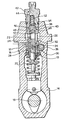
- the drawing illustrates one of the pumping units of a multi-cylinder in-line injection pump for diesel engines.
- this unit comprises a cylinder 10 formed by the cavity of a tubular element 12 inserted in the body 14 of the pump and in which a piston 16 is sealingly slidable.
- the reciprocating sliding of the piston 16 is driven in known manner by a cam 18 with the aid of a biasing spring 20.
- the upper part of the cylinder 10 defines a pressure chamber 22 which communicates through a radial opening 24 with an annular chamber 26 communicating with a fuel supply duct.
- the communication between the delivery opening 24 and the pressure chamber 22 is interrupted during each delivery stroke of the pistons 16, in known manner.
- An axial hole 28 is also formed in the piston 16 and communicates with a helical groove 30 formed in a conventional manner in the lateral surface of the piston 16 and by means of which the pressure chamber 22 can be put into communication with a discharge passage 32 through a radial return opening 34.
- This communication is achieved in known manner through the rotation of the piston 16 about its own axis by means of a slidable rack 36 operated by the accelerator of the engine.
- the pressure chamber 22 is defined on its side opposite the piston 16 by a slide valve 38 which is slidable in a cavity 40 formed in a pressure connector 42 fitted to the top of the body 14 as a replacement for the normal delivery valves with which these pumps are usually provided.
- the pressure connector 42 has a passage 44 for connection to an injector and communicating with an annular chamber 46 sealingly surrounding the slide 38. In its turn, the latter is provided with a series of radial passages 48 opening into an axial passage 50 in permanent communication with the pressure chamber 22.
- the slide valve 38 is movable axially against the action of a biasing spring 52 (replaceable by an equivalent elastic system) between a rest position established by the supply pressure, in which it is displaced towards the piston 16 and the radial passages 48 are staggered axially relative to the chamber 46, and an operative position defining the actual start of pumping, in which it bears against a stop portion 54 of the connector 42 and the passages 48 are located in axial correspondence with the annular chamber 46. In this operative position, communication between the pressure chamber 22 and the delivery passage 44 is open.
- a biasing spring 52 replaceable by an equivalent elastic system
- the pump according to the invention operates as follows.
- the fuel delivery initiation is defined by the movement of the piston 16. This initiation does not occur upon the closure of the intake opening 24 by the piston 16 but afterwards, at the moment when the slide 38 hits the stop 54 of the connector 42 to put the pressure chamber 22 into communication with the delivery passage 44 through the opening 46 and the passages 48 and 50 before the impact. In fact, from the moment of closure of the intake opening 24 to the impact of the slide 38 only a transfer of the volume of the fuel occurs. In limit conditions, this transfer may be made equal to zero.
- the end of delivery is defined by the opening of the discharge between the helical groove 30 in the piston 16 and the return opening 34 communicating with the discharge passage 32.
- the initiation of the delivery of fuel to the injector associated with the passage 44 is defined by the moment when the slide 38 hits the stop 54 of the connector 42.
- the travel of the slide 38 (which is a function of the diameter of the slide 38 and the flexibility of the spring 52 or the equivalent elastic system consequent on the required advance laws) generates a "transfer" volume equal to that generated by the piston 16 at the moment of closure of the intake opening 24.
- the stroke of the piston 16 from the closure of the intake opening 24 to the effective delivery initiation corresponds to a certain angle of rotation of the cam shaft 18.
- This (variable) angle added to the (fixed) angle of the relevant cam from the bottom dead centre position of the piston 16 upon closure of the intake opening 24 defines the cam angle corresponding to the effective initiation of the delivery.
- the external control system for the delivery rate should thus operate by combining the regulation of the supply pressure with the travel of the rack 36.
- control of the delivery initiation by the running conditions/load of the engine in the manner described can be applied to single cylinder pumps or rotary pumps, as well as to multi-cylinder in-line injection pumps.
- the system described above may also operate so as to keep the communication between the openings 48 and 50 and the chamber 56 always open, that is, even with the slide 38 in the rest position.
Landscapes
- Engineering & Computer Science (AREA)
- Chemical & Material Sciences (AREA)
- Combustion & Propulsion (AREA)
- Mechanical Engineering (AREA)
- General Engineering & Computer Science (AREA)
- Fuel-Injection Apparatus (AREA)
- High-Pressure Fuel Injection Pump Control (AREA)
Priority Applications (1)
| Application Number | Priority Date | Filing Date | Title |
|---|---|---|---|
| AT85830269T ATE45206T1 (de) | 1985-02-15 | 1985-10-28 | Kraftstoffeinspritzpumpe fuer dieselmotoren. |
Applications Claiming Priority (2)
| Application Number | Priority Date | Filing Date | Title |
|---|---|---|---|
| IT6716385 | 1985-02-15 | ||
| IT67163/85A IT1182446B (it) | 1985-02-15 | 1985-02-15 | Pompa di iniezione del combustibile per motori a ciclo diesel per autoveicoli con regolazione della portata e dell anticipo di iniezione asservita alla pressione di alimentazione |
Publications (2)
| Publication Number | Publication Date |
|---|---|
| EP0195175A1 true EP0195175A1 (de) | 1986-09-24 |
| EP0195175B1 EP0195175B1 (de) | 1989-08-02 |
Family
ID=11300120
Family Applications (1)
| Application Number | Title | Priority Date | Filing Date |
|---|---|---|---|
| EP85830269A Expired EP0195175B1 (de) | 1985-02-15 | 1985-10-28 | Kraftstoffeinspritzpumpe für Dieselmotoren |
Country Status (6)
| Country | Link |
|---|---|
| US (1) | US4699112A (de) |
| EP (1) | EP0195175B1 (de) |
| JP (1) | JPS61190164A (de) |
| AT (1) | ATE45206T1 (de) |
| DE (1) | DE3572021D1 (de) |
| IT (1) | IT1182446B (de) |
Cited By (1)
| Publication number | Priority date | Publication date | Assignee | Title |
|---|---|---|---|---|
| EP0396127B1 (de) * | 1989-05-03 | 1993-09-08 | Klöckner-Humboldt-Deutz Aktiengesellschaft | Kraftstoffeinspritzvorrichtung |
Families Citing this family (7)
| Publication number | Priority date | Publication date | Assignee | Title |
|---|---|---|---|---|
| CH672168A5 (de) * | 1987-01-30 | 1989-10-31 | Nova Werke Ag | |
| DE3743532A1 (de) * | 1987-12-22 | 1989-07-06 | Bosch Gmbh Robert | Kraftstoffeinspritzanlage fuer brennkraftmaschinen |
| US6655602B2 (en) | 2001-09-24 | 2003-12-02 | Caterpillar Inc | Fuel injector having a hydraulically actuated control valve and hydraulic system using same |
| US7287493B2 (en) | 2004-11-10 | 2007-10-30 | Buck Supply Co., Inc. | Internal combustion engine with hybrid cooling system |
| US7543558B2 (en) | 2004-11-10 | 2009-06-09 | Buck Diesel Engines, Inc. | Multicylinder internal combustion engine with individual cylinder assemblies |
| US7287494B2 (en) | 2004-11-10 | 2007-10-30 | Buck Supply Co., Inc. | Multicylinder internal combustion engine with individual cylinder assemblies and modular cylinder carrier |
| US8316814B2 (en) * | 2009-06-29 | 2012-11-27 | Buck Kenneth M | Toploading internal combustion engine |
Citations (4)
| Publication number | Priority date | Publication date | Assignee | Title |
|---|---|---|---|---|
| GB673107A (en) * | 1949-09-16 | 1952-06-04 | Pal United Works Of Car And Ai | A delivery valve for injection devices, more particularly for internal combustion engines |
| US2612841A (en) * | 1948-09-29 | 1952-10-07 | Louis G Simmons | Variable retraction discharge valve for fuel injection pumps |
| GB727774A (en) * | 1952-05-15 | 1955-04-06 | Emmerich Satzger | An improved injection pump for internal combustion engines |
| GB751160A (en) * | 1953-05-11 | 1956-06-27 | Daimler Benz Ag | Improvements relating to pressure delivery valves in fuel injection pumps of internal combustion engines |
Family Cites Families (7)
| Publication number | Priority date | Publication date | Assignee | Title |
|---|---|---|---|---|
| FR968426A (fr) * | 1948-06-25 | 1950-11-27 | Prec Mecanique | Clapet de pompe de compression |
| US2918048A (en) * | 1953-06-03 | 1959-12-22 | Bosch Gmbh Robert | Control valve arrangement for injection pumps |
| GB1056337A (en) * | 1964-04-25 | 1967-01-25 | Ruston & Hornsby Ltd | Fuel injection pump valves |
| GB1511122A (en) * | 1975-01-15 | 1978-05-17 | Vysoke Uceni Tech Brne | Fuel injection pump for compression ignition engines |
| CS188353B1 (en) * | 1975-02-14 | 1979-03-30 | Jaromir Indra | Displacement valve for the injection pump of the combustion engines |
| CH600150A5 (de) * | 1976-03-09 | 1978-06-15 | Bosch Gmbh Robert | |
| DE3341575C2 (de) * | 1983-11-17 | 1996-06-05 | Bosch Gmbh Robert | Druckventil für Kraftstoffeinspritzpumpen |
-
1985
- 1985-02-15 IT IT67163/85A patent/IT1182446B/it active
- 1985-10-28 DE DE8585830269T patent/DE3572021D1/de not_active Expired
- 1985-10-28 EP EP85830269A patent/EP0195175B1/de not_active Expired
- 1985-10-28 AT AT85830269T patent/ATE45206T1/de not_active IP Right Cessation
- 1985-11-06 US US06/795,599 patent/US4699112A/en not_active Expired - Fee Related
- 1985-11-22 JP JP60263594A patent/JPS61190164A/ja active Pending
Patent Citations (4)
| Publication number | Priority date | Publication date | Assignee | Title |
|---|---|---|---|---|
| US2612841A (en) * | 1948-09-29 | 1952-10-07 | Louis G Simmons | Variable retraction discharge valve for fuel injection pumps |
| GB673107A (en) * | 1949-09-16 | 1952-06-04 | Pal United Works Of Car And Ai | A delivery valve for injection devices, more particularly for internal combustion engines |
| GB727774A (en) * | 1952-05-15 | 1955-04-06 | Emmerich Satzger | An improved injection pump for internal combustion engines |
| GB751160A (en) * | 1953-05-11 | 1956-06-27 | Daimler Benz Ag | Improvements relating to pressure delivery valves in fuel injection pumps of internal combustion engines |
Cited By (1)
| Publication number | Priority date | Publication date | Assignee | Title |
|---|---|---|---|---|
| EP0396127B1 (de) * | 1989-05-03 | 1993-09-08 | Klöckner-Humboldt-Deutz Aktiengesellschaft | Kraftstoffeinspritzvorrichtung |
Also Published As
| Publication number | Publication date |
|---|---|
| ATE45206T1 (de) | 1989-08-15 |
| JPS61190164A (ja) | 1986-08-23 |
| IT8567163A1 (it) | 1986-08-15 |
| IT1182446B (it) | 1987-10-05 |
| IT8567163A0 (it) | 1985-02-15 |
| US4699112A (en) | 1987-10-13 |
| EP0195175B1 (de) | 1989-08-02 |
| DE3572021D1 (en) | 1989-09-07 |
Similar Documents
| Publication | Publication Date | Title |
|---|---|---|
| US4777921A (en) | Fuel injection system | |
| US4633837A (en) | Method for controlling fuel injection in internal combustion engines and fuel injection system for performing the method | |
| EP0643221B1 (de) | Kraftstoffzufuhreinrichtung | |
| US4699103A (en) | Fuel injection system | |
| US4463725A (en) | Fuel injection device for internal combustion engines, in particular a pump/nozzle for diesel engines | |
| US4407250A (en) | Fuel injection system | |
| US4211203A (en) | Fuel injection pump | |
| US4402290A (en) | Fuel injection pump | |
| EP1612402B1 (de) | Hochdruckpumpe mit variabler Förderrate für ein Brennstoffeinspritzsystem | |
| US4699112A (en) | Fuel injection pump for diesel engines | |
| US4831986A (en) | Fuel injection pump | |
| US4475519A (en) | Fuel injection system for internal combustion engines | |
| US5040511A (en) | Fuel injection device for internal combustion engines, in particular unit fuel injector | |
| US6016786A (en) | Fuel injection system | |
| US4550702A (en) | Spill control system for distributor pump | |
| US5146894A (en) | Reservoir-type fuel injection system | |
| US4271805A (en) | Fuel injection pump | |
| US6092514A (en) | Fuel injection system for an internal combustion engine | |
| US4534332A (en) | Fuel injection pump for internal combustion engines with an adjustment of the instant of injection | |
| US4598683A (en) | Fuel injection pump of the distribution type | |
| US2949904A (en) | Fuel injection pump | |
| US5138999A (en) | Fuel pumping apparatus | |
| US5032066A (en) | Control device for a fuel injection pump | |
| GB2196153A (en) | Fuel system for a multi-cylinder engine | |
| GB2227105A (en) | A fuel injection pump for internal combustion engines |
Legal Events
| Date | Code | Title | Description |
|---|---|---|---|
| PUAI | Public reference made under article 153(3) epc to a published international application that has entered the european phase |
Free format text: ORIGINAL CODE: 0009012 |
|
| AK | Designated contracting states |
Kind code of ref document: A1 Designated state(s): AT BE CH DE FR GB IT LI LU NL SE |
|
| 17P | Request for examination filed |
Effective date: 19870114 |
|
| 17Q | First examination report despatched |
Effective date: 19870527 |
|
| RAP1 | Party data changed (applicant data changed or rights of an application transferred) |
Owner name: WEBER S.P.A. |
|
| GRAA | (expected) grant |
Free format text: ORIGINAL CODE: 0009210 |
|
| RAP1 | Party data changed (applicant data changed or rights of an application transferred) |
Owner name: WEBER S.R.L. |
|
| AK | Designated contracting states |
Kind code of ref document: B1 Designated state(s): AT BE CH DE FR GB IT LI LU NL SE |
|
| REF | Corresponds to: |
Ref document number: 45206 Country of ref document: AT Date of ref document: 19890815 Kind code of ref document: T |
|
| REF | Corresponds to: |
Ref document number: 3572021 Country of ref document: DE Date of ref document: 19890907 |
|
| ITF | It: translation for a ep patent filed | ||
| PG25 | Lapsed in a contracting state [announced via postgrant information from national office to epo] |
Ref country code: LU Free format text: LAPSE BECAUSE OF NON-PAYMENT OF DUE FEES Effective date: 19891031 |
|
| ET | Fr: translation filed | ||
| PLBE | No opposition filed within time limit |
Free format text: ORIGINAL CODE: 0009261 |
|
| STAA | Information on the status of an ep patent application or granted ep patent |
Free format text: STATUS: NO OPPOSITION FILED WITHIN TIME LIMIT |
|
| 26N | No opposition filed | ||
| PGFP | Annual fee paid to national office [announced via postgrant information from national office to epo] |
Ref country code: AT Payment date: 19900920 Year of fee payment: 6 |
|
| PGFP | Annual fee paid to national office [announced via postgrant information from national office to epo] |
Ref country code: FR Payment date: 19900928 Year of fee payment: 6 |
|
| PGFP | Annual fee paid to national office [announced via postgrant information from national office to epo] |
Ref country code: CH Payment date: 19901001 Year of fee payment: 6 |
|
| PGFP | Annual fee paid to national office [announced via postgrant information from national office to epo] |
Ref country code: LU Payment date: 19901003 Year of fee payment: 6 |
|
| PGFP | Annual fee paid to national office [announced via postgrant information from national office to epo] |
Ref country code: BE Payment date: 19901008 Year of fee payment: 6 |
|
| PGFP | Annual fee paid to national office [announced via postgrant information from national office to epo] |
Ref country code: SE Payment date: 19901016 Year of fee payment: 6 |
|
| PGFP | Annual fee paid to national office [announced via postgrant information from national office to epo] |
Ref country code: GB Payment date: 19901018 Year of fee payment: 6 |
|
| ITTA | It: last paid annual fee | ||
| PGFP | Annual fee paid to national office [announced via postgrant information from national office to epo] |
Ref country code: NL Payment date: 19901031 Year of fee payment: 6 |
|
| PGFP | Annual fee paid to national office [announced via postgrant information from national office to epo] |
Ref country code: DE Payment date: 19901207 Year of fee payment: 6 |
|
| PG25 | Lapsed in a contracting state [announced via postgrant information from national office to epo] |
Ref country code: GB Effective date: 19911028 Ref country code: AT Effective date: 19911028 |
|
| PG25 | Lapsed in a contracting state [announced via postgrant information from national office to epo] |
Ref country code: SE Effective date: 19911029 |
|
| PG25 | Lapsed in a contracting state [announced via postgrant information from national office to epo] |
Ref country code: LI Effective date: 19911031 Ref country code: CH Effective date: 19911031 Ref country code: BE Effective date: 19911031 |
|
| BERE | Be: lapsed |
Owner name: WEBER S.R.L. Effective date: 19911031 |
|
| PG25 | Lapsed in a contracting state [announced via postgrant information from national office to epo] |
Ref country code: NL Effective date: 19920501 |
|
| NLV4 | Nl: lapsed or anulled due to non-payment of the annual fee | ||
| GBPC | Gb: european patent ceased through non-payment of renewal fee | ||
| PG25 | Lapsed in a contracting state [announced via postgrant information from national office to epo] |
Ref country code: FR Effective date: 19920630 |
|
| REG | Reference to a national code |
Ref country code: CH Ref legal event code: PL |
|
| PG25 | Lapsed in a contracting state [announced via postgrant information from national office to epo] |
Ref country code: DE Effective date: 19920701 |
|
| REG | Reference to a national code |
Ref country code: FR Ref legal event code: ST |
|
| EUG | Se: european patent has lapsed |
Ref document number: 85830269.8 Effective date: 19920510 |