EP0195176B1 - Vorrichtung zum Füllen von Hohlkörpern mit Granulat - Google Patents
Vorrichtung zum Füllen von Hohlkörpern mit Granulat Download PDFInfo
- Publication number
- EP0195176B1 EP0195176B1 EP85890144A EP85890144A EP0195176B1 EP 0195176 B1 EP0195176 B1 EP 0195176B1 EP 85890144 A EP85890144 A EP 85890144A EP 85890144 A EP85890144 A EP 85890144A EP 0195176 B1 EP0195176 B1 EP 0195176B1
- Authority
- EP
- European Patent Office
- Prior art keywords
- spacer frame
- section
- conduit
- frame
- plate
- Prior art date
- Legal status (The legal status is an assumption and is not a legal conclusion. Google has not performed a legal analysis and makes no representation as to the accuracy of the status listed.)
- Expired
Links
- 239000008187 granular material Substances 0.000 title claims description 60
- 125000006850 spacer group Chemical group 0.000 claims description 99
- 238000005429 filling process Methods 0.000 claims description 11
- 239000011521 glass Substances 0.000 claims description 11
- 239000000463 material Substances 0.000 claims description 11
- 238000003825 pressing Methods 0.000 claims description 4
- 238000003754 machining Methods 0.000 description 8
- 238000005553 drilling Methods 0.000 description 7
- 238000003860 storage Methods 0.000 description 7
- 230000008901 benefit Effects 0.000 description 4
- 239000000428 dust Substances 0.000 description 3
- 238000000034 method Methods 0.000 description 3
- 239000002808 molecular sieve Substances 0.000 description 3
- URGAHOPLAPQHLN-UHFFFAOYSA-N sodium aluminosilicate Chemical compound [Na+].[Al+3].[O-][Si]([O-])=O.[O-][Si]([O-])=O URGAHOPLAPQHLN-UHFFFAOYSA-N 0.000 description 3
- 230000007704 transition Effects 0.000 description 3
- 238000005452 bending Methods 0.000 description 2
- 230000015572 biosynthetic process Effects 0.000 description 2
- 239000000945 filler Substances 0.000 description 2
- 230000010355 oscillation Effects 0.000 description 2
- 230000008569 process Effects 0.000 description 2
- 230000004888 barrier function Effects 0.000 description 1
- 239000013590 bulk material Substances 0.000 description 1
- 150000001875 compounds Chemical class 0.000 description 1
- 238000010276 construction Methods 0.000 description 1
- 238000006073 displacement reaction Methods 0.000 description 1
- 230000000694 effects Effects 0.000 description 1
- 239000006260 foam Substances 0.000 description 1
- 230000009467 reduction Effects 0.000 description 1
- 238000007789 sealing Methods 0.000 description 1
Images




Classifications
-
- E—FIXED CONSTRUCTIONS
- E06—DOORS, WINDOWS, SHUTTERS, OR ROLLER BLINDS IN GENERAL; LADDERS
- E06B—FIXED OR MOVABLE CLOSURES FOR OPENINGS IN BUILDINGS, VEHICLES, FENCES OR LIKE ENCLOSURES IN GENERAL, e.g. DOORS, WINDOWS, BLINDS, GATES
- E06B3/00—Window sashes, door leaves, or like elements for closing wall or like openings; Layout of fixed or moving closures, e.g. windows in wall or like openings; Features of rigidly-mounted outer frames relating to the mounting of wing frames
- E06B3/66—Units comprising two or more parallel glass or like panes permanently secured together
- E06B3/673—Assembling the units
- E06B3/67304—Preparing rigid spacer members before assembly
- E06B3/67317—Filling of hollow spacer elements with absorbants; Closing off the spacers thereafter
-
- Y—GENERAL TAGGING OF NEW TECHNOLOGICAL DEVELOPMENTS; GENERAL TAGGING OF CROSS-SECTIONAL TECHNOLOGIES SPANNING OVER SEVERAL SECTIONS OF THE IPC; TECHNICAL SUBJECTS COVERED BY FORMER USPC CROSS-REFERENCE ART COLLECTIONS [XRACs] AND DIGESTS
- Y10—TECHNICAL SUBJECTS COVERED BY FORMER USPC
- Y10S—TECHNICAL SUBJECTS COVERED BY FORMER USPC CROSS-REFERENCE ART COLLECTIONS [XRACs] AND DIGESTS
- Y10S29/00—Metal working
- Y10S29/063—Fluid conveyor or applicator
-
- Y—GENERAL TAGGING OF NEW TECHNOLOGICAL DEVELOPMENTS; GENERAL TAGGING OF CROSS-SECTIONAL TECHNOLOGIES SPANNING OVER SEVERAL SECTIONS OF THE IPC; TECHNICAL SUBJECTS COVERED BY FORMER USPC CROSS-REFERENCE ART COLLECTIONS [XRACs] AND DIGESTS
- Y10—TECHNICAL SUBJECTS COVERED BY FORMER USPC
- Y10T—TECHNICAL SUBJECTS COVERED BY FORMER US CLASSIFICATION
- Y10T29/00—Metal working
- Y10T29/49—Method of mechanical manufacture
- Y10T29/49826—Assembling or joining
- Y10T29/49879—Spaced wall tube or receptacle
-
- Y—GENERAL TAGGING OF NEW TECHNOLOGICAL DEVELOPMENTS; GENERAL TAGGING OF CROSS-SECTIONAL TECHNOLOGIES SPANNING OVER SEVERAL SECTIONS OF THE IPC; TECHNICAL SUBJECTS COVERED BY FORMER USPC CROSS-REFERENCE ART COLLECTIONS [XRACs] AND DIGESTS
- Y10—TECHNICAL SUBJECTS COVERED BY FORMER USPC
- Y10T—TECHNICAL SUBJECTS COVERED BY FORMER US CLASSIFICATION
- Y10T29/00—Metal working
- Y10T29/51—Plural diverse manufacturing apparatus including means for metal shaping or assembling
- Y10T29/5136—Separate tool stations for selective or successive operation on work
- Y10T29/5137—Separate tool stations for selective or successive operation on work including assembling or disassembling station
-
- Y—GENERAL TAGGING OF NEW TECHNOLOGICAL DEVELOPMENTS; GENERAL TAGGING OF CROSS-SECTIONAL TECHNOLOGIES SPANNING OVER SEVERAL SECTIONS OF THE IPC; TECHNICAL SUBJECTS COVERED BY FORMER USPC CROSS-REFERENCE ART COLLECTIONS [XRACs] AND DIGESTS
- Y10—TECHNICAL SUBJECTS COVERED BY FORMER USPC
- Y10T—TECHNICAL SUBJECTS COVERED BY FORMER US CLASSIFICATION
- Y10T29/00—Metal working
- Y10T29/51—Plural diverse manufacturing apparatus including means for metal shaping or assembling
- Y10T29/5191—Assembly
Definitions
- the invention relates to a device for filling hollow bodies with granules, in particular spacer frames for insulating glass with granular, hygroscopic material, with a line connecting a storage container for the granules with an outlet opening.
- the spacer frames of insulating glass panes are regularly filled with granular, hygroscopic material (molecular sieve) in order to bind the moisture contained in the interior of the pane.
- hygroscopic material molecular sieve
- the procedure is usually that the hollow profile sections are filled with the hygroscopic material and then closed at both ends with foam plugs. This can be done, for example, with the aid of the device known from AT-A-365 551.
- Spacer frames for insulating glass which have been made from a single hollow profile section by multiple bending, cannot be filled with the hygroscopic material before bending, because on the one hand too much time elapses before the spacer frame is installed in the insulating glass and a considerable part of the capacity of the hygroscopic Material is exhausted before the insulating glass is finished and, on the other hand, because when the hollow profile strip is bent, granules are crushed to dust, which then penetrates through the openings in the hollow profile strip into the inside of the pane and is deposited on the inner surfaces of the glass panes.
- a device has therefore already been proposed (cf. DE-A-32 24 862) with which integrally curved spacer frames for insulating glass can be filled with hyroscopic material.
- a problem with the handling of granular hygroscopic material is that it is very abrasive, so that conventional shut-off devices such as valves, slides and the like. Like., Which are used to control the bulk flow, wear out very quickly. On the other hand, there is a risk that the granules will be crushed to dust when the shut-off elements are actuated, which again results in the disadvantage described above.
- the invention has for its object to provide a device of the type mentioned, with which the bulk flow when filling hollow bodies, in particular spacer frames, without the risk that the granules are crushed and shut-off devices are provided which are subject to increased wear and tear can.
- a device for filling hollow bodies with granules is characterized in that the line for the granules is deflected upwards in front of the outlet opening and has a section with a cross section which is smaller than the cross section of the remaining section immediately in front of the outlet opening the line, that the axis of the section with a smaller cross section is offset, in particular upwards, relative to the axis of the section of the line in its region adjacent to the section of the line with a smaller cross section, and that the line is provided with a vibration generator and / or a device for Generating a feed gas stream is assigned.
- the granulate moves through the line for the granulate via the outlet opening into the hollow body to be filled.
- the vibration generator is stopped or the feed gas flow is interrupted, the granules accumulate in the transition from the section of the line with a larger cross section to the section of the line with a smaller cross section, which is further reinforced by the fact that the section of the line connected to the Exit opening is adjacent, is deflected upwards.
- the vibration generator and / or the conveying gas flow are effective again, the jam in the granulate is removed and this flows back into the hollow body to be filled.
- the storage container for the granulate is arranged above the outlet opening, the section of the line having a larger cross section being deflected from a vertical section into a horizontal section of the line.
- a further possibility for facilitating the formation of the congestion interrupting the bulk flow in the line is that the section of the line with a smaller cross section is oriented obliquely upwards.
- the end of the filling process can be determined simply by assigning a bulk flow detector to the line for the granulate.
- a bulk flow detector monitors the movement of the granules in the line according to the radar principle.
- the bulk flow detector emits a control signal which stops the vibration generator or the device for generating the conveying gas flow when the granulate is stationary in the line.
- the hollow body to be filled can be removed from the device after the filling process has ended, without there being any risk of granules still escaping from the outlet opening, since immediately after the vibration generator and / or the bulk flow has stopped in the line for the Granules that form a traffic jam.
- the invention further relates to a device for filling spacer frames for insulating glass of the type known from DE-A-32 24 862, which is equipped with at least one, but preferably two filling devices according to the invention and with a holder for the spacer frame to be filled and with at least one , but preferably two processing arrangements which are arranged on a machine frame and which are each equipped with a drilling device for creating filling openings in the spacer frame to be filled and with a device for closing the filling openings after completion of the filling process.
- Such a device is characterized according to the invention in that the holder of the processing arrangement has a clamping device that engages on one leg of the spacer frame and a pressure stamp, that the processing device has a plate opposite the pressure stamp, which has a contact surface that extends parallel to the plane of the spacer frame, in which a hole for the passage of a drill of the drilling device, a channel for the granulate and a channel for a mass for closing the filler opening in the spacer frame and that drive motors are provided for a relative movement between the plate and the spacer frame, around the leg of the spacer frame Place a hole for the drill, then the mouth of the channel for the granulate and finally the mouth of the channel for the mass to close the filling opening in the spacer frame .
- the specially designed clamping device reliably holds the leg or legs of the spacer frame, via which the filling process is to be carried out.
- the movements to be carried out during the filling process are limited to linear displacements in order to move the spacer frame into the correct position for the respective processing step (drilling, filling, closing). Compared to the device known from DE-OS 32 24 862, this represents a not inconsiderable simplification of construction.
- the pressure stamp for pressing the spacer frame against the plate is arranged opposite in the rest position of the mouth of the channel for the granulate and closes the mouth when the spacer frame is removed.
- This stamp therefore has a double function; on the one hand he holds the spacer frame in contact with the plate and on the other hand he closes the mouth of the pipe for the granulate so that it is protected against moisture.
- the or each processing arrangement has a base plate and an auxiliary plate which can be displaced relative to the latter, the plate with the hole for the drill of the drilling device and the channels for the granulate or the mass for closing the filling opening in the spacer frame and a storage cylinder for the mass for closing the opening in the spacer frame on the movable auxiliary plate, the clamping device and the pressure stamp on the base plate.
- This embodiment has u. a. the advantage that after the opening created in the spacer frame is closed, a protruding mass is wiped off by a sliding movement of the spacer frame relative to the plate.
- the auxiliary plate is guided on the base plate over a horizontal rail and in the region of its lower edge between rollers on the base plate.
- the metering of the mass for closing the opening (s) created in the spacer frame is particularly easy if a feed cylinder for the mass for closing the filling opening in the spacer frame is assigned a piston which can be pushed forward and by means of which a predetermined amount of mass required for a closing process in the channel provided in the plate for the mass to close the Filling opening can be pressed into the spacer frame, and that a pushable piston for pressing out the mass from the channel is accommodated in the filling opening in the spacer frame in the channel.
- the clamping device on the processing arrangement has a stop rigidly arranged on the base plate and a clamping jaw which can be placed on the leg of the spacer frame and is pivotably mounted on the base plate.
- the spacer frame is clamped from both sides and additionally pressed against the plate by the pressure stamp, so that it is held securely during the relative movements between the spacer frame and the plate.
- the pivotable clamping jaw is angled and is mounted on the base plate so as to be pivotable about a preferably vertical axis via two legs perpendicular to its pressure surface. If, according to a further proposal of the invention, the pressure stamp extends through the movable clamping jaw between the legs thereof, then a spatially advantageous arrangement results.
- the drilling device can be pushed forward on the base plate for carrying out the drilling work transversely to the level of the spacer frame.
- a horizontally oriented bar provided with hooks is provided on the frame of the device, into which hooks a spacer frame can be hung and that the processing arrangement (s) is a vertical leg (s) of the spacer frame is (are) assigned.
- the processing arrangement (s) is a vertical leg (s) of the spacer frame is (are) assigned.
- the stop of the clamping device can be placed on the outer surface and the clamping jaw on the inner surface of one leg of the spacer frame.
- the plate with the hole for the drill and the channels for the granulate or the mass for closing the filling opening of the spacer frame can be placed against a surface of one leg of the spacer frame that runs parallel to the plane of the spacer frame.
- a guide rail which is preferably arranged higher than the guide rail, is provided on the displaceable machining arrangement on the side of the spacer frame facing away from the machine frame. This ensures that the leg of the spacer frame associated with the movable processing arrangement is moved into the vicinity of the plate before the clamping device is closed and the plunger is moved forward when the movable processing arrangement is delivered.
- a device for filling spacer frames 1 for insulating glass panes comprises two processing arrangements 2 and 3 carried by a machine frame (not shown in more detail).
- the processing arrangement 2 is fixed in the machine frame and the processing arrangement 3 is horizontally displaceable in the machine frame.
- the structure of the machining arrangement 2 and 3 is explained below with reference to FIGS. 1a and 2 using the example of the machining arrangement 2 which is stationary in the machine frame.
- the processing arrangement 2 has a base plate 10 connected to the machine frame and an auxiliary plate 11 guided horizontally back and forth on it.
- the auxiliary plate 11 on the base plate 10 is over a guide rail 12 is supported, in the region of the lower edge 13 of the auxiliary plate 11 on both sides guide rollers 14 which are mounted on the base plate 10.
- a pressure medium motor 15 is provided for moving the auxiliary plate 11 relative to the base plate 10.
- a plate 16 is provided on the movable auxiliary plate 11.
- This plate 16 has a hole 17 for the passage of a drill 18, which is guided on the base plate 10 or — as in the exemplary embodiment — on the auxiliary plate 11, transversely to the surface extension of the base plate 10 or the auxiliary plate 11, and can be pushed back and forth.
- a pressure medium motor 20 which engages, for example, the motor 19 for the drill 18, is provided.
- a channel 21 for the supply of granules.
- another channel 22 opens into the plate 16, via which a mass can be supplied, with which the filling openings created in the legs 6 and 7 of the spacer frame 1 can be closed again after the filling process has ended.
- This mass is kept in a cartridge 23 which can be acted upon by the piston of a pressure medium motor 24.
- a further piston 25 is assigned to the channel 22 and can be advanced by a pressure medium motor 26. When the piston 25 is pushed forward, the amount of mass pressed into the channel 22 by the actuation of the pressure medium motor 24 is pushed out of the cartridge 23 out of the mouth 27 of the channel 22 and pressed into the filling opening created in the spacer frame in order to close it.
- a clamping device 30 is provided, which is supported by the base plate 10.
- the clamping device 30 comprises a stop 31 and a pivotable clamping jaw 32, which is angled and is pivotably mounted about two legs 33 on a carrier 34 connected to the base plate 10 about an essentially vertical axis.
- a pressure medium motor 35 is provided to confirm the clamping jaw 32.
- the clamping jaw 32 In the embodiment of the clamping jaw 32 shown in FIG. 1 b, the latter is simply angled, i. H. their legs 33 are perpendicular to their pressure surface 36, the piston rod of the pressure medium motor 35 engaging a shoulder 37.
- a pressure stamp 40 protrudes towards the plate 16, the pressure stamp 40 closing the mouth 41 of the channel 21, through which the granulate can be fed, in the rest position of the processing arrangement 2.
- the pressure stamp 40 is pressed forward with the aid of a spring 42, so that, as can be seen from FIG. 1, it rests against a side surface of the vertical leg 6 of the spacer frame 1 and presses it against the plate 16.
- a pressure medium motor 43 is assigned to the pressure stamp 40, by means of which the pressure stamp 40 can be lifted off the frame leg 6 or the plate 16.
- the pressure medium motor 43 and thus also the pressure stamp 40 are fastened to the carrier 34 via an auxiliary carrier 44 and are thus rigidly connected to the base plate 10 of the machining arrangement 2.
- the movable processing arrangement 3 has a corresponding, partially mirror-symmetrical structure with the proviso that in the plate 16 of the movable processing arrangement 3, the mouth 41 of the channel 21 for granules, the mouth 27 of the channel 22 for the sealing compound and the hole 17 for the passage of the drill 18 are arranged in the same order as in the plate 16 of the stationary processing arrangement 2 (see FIG. 3 ff.).
- guide strips 50 are also provided, which are arranged in the same vertical plane as the front surfaces of the plates 16, so that the legs 6 and 7 of the spacer frame 1 rest against the guide rails 50 with the spacer frame 1 hanging vertically.
- a further guide bar 51 is provided on the movable processing arrangement just below its clamping device 30, which bears against the leg 7 of the spacer frame 1 from the front.
- the device for filling the spacer frame 1 with granules is described below with reference to FIGS. 10 and 2, it being noted that this device is also independent of the previously described device for filling Spacer frame can be used wherever bulk flows of granules, in particular of abrasive granules that can be easily crushed to dust, have to be controlled.
- the device for filling hollow bodies with granules comprises a storage container 60 for the granules, which is connected via a line 61 to an outlet opening 41, the outlet opening 41 being provided in the exemplary embodiment shown in the plate 16 of the device according to FIGS. 1 and 2.
- the hollow body is pressed by a pressure stamp 40 against the plate 16, the pressure stamp 40 at sauce taken hollow body closes the mouth 41. This is particularly important in the case of hygroscopic granules (molecular sieve), as is used to fill spacer frames.
- the line 61 comprises a vertical section 63, a horizontal section 64 and an obliquely upwardly extending section 65, the end of the obliquely upwardly extending section 65 immediately adjacent to the mouth 41 being oriented essentially horizontally.
- the sections 63 and 64 of the line 61 have a larger cross section (diameter) than the section 65 of the same which extends obliquely upwards.
- the obliquely upwardly extending section 65 with a smaller cross section is offset upwards from the horizontal section 64, so that a step 67 results in the line 61 in the transition region of the sections with a larger cross section to the section with a smaller cross section.
- An oscillation generator is assigned to the line 61 and / or the storage container 60 and generates oscillation strokes which are aligned parallel to the section 63 of the line 61 and predominantly act downwards.
- a device for generating a conveying gas stream which is dried in the case of granules of hygroscopic material, can be assigned to convey the granules from the storage container 60 through the line 61.
- a line flow detector 68 is assigned to line 61, preferably vertical section 63 thereof, which detects movements of the granules through line 61, for example with the aid of the radar principle.
- the filling flow detector which now no longer detects any movement of the granulate, emits a control signal which stops the vibration generator and / or the device for generating the conveying gas flow.
- the hollow body now filled with granules can then be removed. Since the granulate jams in the transition region 66 between the line sections 63, 64 with a larger cross section and the upwardly directed section 65 of the line with a smaller cross section, if no vibrations are generated or no conveying gas flow is passed through the line 61, there is no danger that at removed hollow body of granules from the reservoir 60 via the line 61 from the mouth 41.
- the pressure stamp 40 therefore does not have the task of preventing granules from escaping from the mouth 41, but rather serves exclusively to press the hollow body against the plate 16 and to close the mouth against the ingress of moisture from the outside.
- FIGS. 1, 1a and 2 The operation of the device shown in FIGS. 1, 1a and 2 is explained below with reference to FIGS. 3 to 9.
- a spacer frame is hung with its upper horizontal leg on the hook 5 of the hook bar 4.
- the movable machining arrangement 3 as shown in FIG. 3, is moved onto the vertical leg 6 of the spacer frame 1 until the stops 31 of the machining arrangement lie against the outer surfaces of the vertical legs 6 and 7.
- the jaws 32 are pivoted into their operative position, in which their bearing surfaces 36 bear against the inner surfaces of the legs 6 and 7 and preferably shortly before the pressure stamp 40 is moved so that the legs 6 and 7 of the spacer frame 1 against the plates 16 of both processing arrangements 2 and 3 are present (FIG. 4).
- the vertical legs 6 and 7 of the spacer frame 1 are arranged opposite the holes 17 for the drill 18, so that, as shown in FIG. 6, the drill 18 operates to create the filling openings in the spacer frame 1 can be.
- the auxiliary plate 11 and thus also the plate 16 connected to it are displaced, so that the mouths 41 of the channels (lines 61) for the feeding of granulate face the previously created fill holes 62.
- the vibration generator is started up or a conveying gas flow is generated, so that the granulate from the storage container 60 enters the spacer frame 1 via the line 61 (FIG. 7).
- the auxiliary plates 11 with respect to the base plates 10 of both processing arrangements 2 and 3 moves one step until the mouths 27 of the channels 22 are aligned for the supply of mass from the cartridge 23 (position according to FIG. 8).
- the pressure medium motors 24 are actuated in order to press a predetermined amount of mass from the cartridges 23 into the channel 22, whereupon the pressure medium motors 26 actuate the press-in punches 25, so that the amount of mass contained in the channel 22 for closing the filler openings 62 in the vertical legs 6 and 7 of the spacer frame 1 is pressed.
- the now stationary piston of the pressure medium motor 24 prevents backflow of mass from the channel 22 into the cartridge 23.
- the plates 16 are actuated by the pressure medium motors 15 relative to the legs 6 and 7 held by the clamping devices 30 to the right or, as in FIG 9 shown, shifted to the left in order to smoothly strip the mass closing the filling openings 62.
- a completely filled spacer frame can be removed from the front direction can be taken.
- the workflow just described for filling spacer frames can take place partially or completely automatically, for which purpose the device, not shown, is assigned to limit switches (for example light barriers and the like) which control the movements, in particular the delivery of the movable processing arrangement 3.
Landscapes
- Engineering & Computer Science (AREA)
- Civil Engineering (AREA)
- Structural Engineering (AREA)
- Control And Other Processes For Unpacking Of Materials (AREA)
- Basic Packing Technique (AREA)
- Devices And Processes Conducted In The Presence Of Fluids And Solid Particles (AREA)
- Drilling And Boring (AREA)
Description
- Die Erfindung betrifft eine Vorrichtung zum Füllen von Hohlkörpern mit Granulat, insbesondere von Abstandhalterrahmen für Isolierglas mit granulatförmigem, hygroskopischem Material, mit einer einen Vorratsbehälter für das Granulat mit einer Austrittsöffnung verbindenden Leitung.
- Die Abstandhalterrahmen von Isolierglasscheiben sind regelmässig mit granulatförmigem, hygroskopischem Material (Molekularsieb) gefüllt, um die im Scheibeninnenraum enthaltene Feuchtigkeit zu binden. Bei Abstandhalterrahmen, die aus geraden Hohlprofilabschnitten unter Verwendung von Eckwinkeln zusammengesetzt sind, wird für gewöhnlich so vorgegangen, dass die Hohlprofilabschnitte mit dem hygroskopischen Material gefüllt und dann an beiden Enden mit Schaumstoffpfropfen verschlossen werden. Dies kann beispielsweise unter Zuhilfenahme der aus der AT-A-365 551 bekannten Vorrichtung erfolgen.
- Abstandhaiterrahmen für Isolierglas, die aus einem einzigen Hohlprofilabschnitt durch mehrfaches Abbiegen gefertigt worden sind, können vor dem Biegen nicht mit dem hygroskopischen Material gefüllt werden, da einerseits bis zum Einbau des Abstandhalterrahmens in das Isolierglas zu viel Zeit vergeht und ein erheblicher Teil der Kapazität des hygroskopischen Materials erschöpft wird, bevor das Isolierglas fertig ist und anderseits, weil beim Biegen der Hohlprofilleiste Granulat zu Staub zerdrückt wird, der dann durch die Öffnungen in der Hohlprofilleiste in das Scheibeninnere eindringt und sich auf den Innenflächen der Glasscheiben niederschlägt. Es ist daher auch schon eine Vorrichtung vorgeschlagen worden (vgl. DE-A-32 24 862), mit der eintückig gebogene Abstandhalterrahmen für Isolierglas mit hykroskopischem Material gefüllt werden können.
- Ein Problem bei der Handhabung von granulatförmigem hygroskopischem Material besteht darin, dass dieses sehr abrasiv ist, so dass herkömmliche Absperrorgane, wie Ventile, Schieber u. dgl., die zur Steuerung des Schüttstromes herangezogen werden, sehr rasch verschleissen. Anderseits besteht die Gefahr, dass das Granulat bei der Betätigung der Absperrorgane zu Staub zerdrückt wird, wodurch sich wieder der weiter oben geschilderte Nachteil einstellt.
- Der Erfindung liegt eine Aufgabe zugrunde, eine Vorrichtung der eingangs genannten Gattung anzugeben, mit der der Schüttstrom beim Füllen von Hohlkörpern, insbesondere von Abstandhalterahmen, ohne die Gefahr, dass das Granulat zerdrückt wird und Absperrorgane vorgesehen sind, die einem erhöhten Verschleiss unterliegen, gesteuert werden kann.
- In Lösung dieser Aufgabe ist eine Vorrichtung zum Füllen von Hohlkörpern mit Granulat dadurch gekennzeichnet, dass die Leitung für das Granulat vor der Austrittsöffnung nach oben umgelenkt ist und unmittelbar vor der Austrittsöffnung einen Abschnitt mit einem Querschnitt aufweist, der kleiner ist als der Querschnitt des übrigen Abschnittes der Leitung, dass die Achse des Abschnittes mit kleinerem Querschnitt gegenüber der Achse des Abschnittes der Leitung in ihrem an den Abschnitt der Leitung mit kleinerem Querschnitt angrenzenden Bereich versetzt, insbesondere nach oben versetzt ist, und dass der Leitung ein Schwingungserzeuger und/oder eine Vorrichtung zum Erzeugen eines Fördergasstromes zugeordnet ist.
- Bei der erfindungsgemässen Vorrichtung bewegt sich das Granulat, solange der Schwingungserzeuger und/oder der Fördergasstrom wirksam ist, durch die Leitung für das Granulat über die Austrittsöffnung in den zu füllenden Hohlkörper. Sobald jedoch der Schwingungserzeuger stillgesetzt wird bzw. der Fördergasstrom unterbrochen wird, staut sich das Granulat im Übergang vom Abschnitt der Leitung mit grösserem Querschnitt in den Abschnitt der Leitung mit kleinerem Querschnitt, was noch dadurch verstärkt wird, dass der Abschnitt der Leitung, der an die Austrittsöffnung angrenzt, nach oben umgelenkt ist. Sobald der Schwingungserzeuger und/ oder der Fördergasstrom wieder wirksam sind, wird der Stau im Granulat aufgehoben und dieses strömt wieder in den zu füllenden Hohlkörper ein.
- Es ist ersichtlich, dass aufgrund der besonderen Ausbildung der Leitung der erfindungsgemässen Vorrichtung zum Füllen von Hohlkörpern mit Granulat zum Unterbrechen des Schüttstromes in der Leitung keinerlei Absperrorgane mit bewegten Teilen erforderlich sind.
- In einer Ausführungsform der Erfindung kann vorgesehen sein, dass der Vorratsbehälter für das Granulat oberhalb der Austrittsöffnung angeordnet ist, wobei der Abschnitt der Leitung mit grösserem Querschnitt aus einem vertikalen Abschnitt in einen waagerechten Abschnitt der Leitung umgelenkt ist. Die Ausführungsform hat zwei Vorteile, da einmal die Ausbildung des Staus zum Unterbrechen des Schüttstromes erleichtert wird und dass anderseits das Granulat den Hohlkörper auch in einem oberhalb der Austrittsöffnung liegenden Abschnitt füllt.
- Das Eintreten des Granulats aus der Austrittsöffnung in den zu füllenden Hohlkörper wird erleichtert, wenn der der Austrittsöffnung unmittelbar benachbarte Bereich des Abschnittes der Leitung mit kleinerem Querschnitt im wesentlichen horizontal verläuft.
- Eine weitere Möglichkeit, die Ausbildung des den Schüttstrom unterbrechenden Staus in der Leitung zu erleichtern, besteht darin, dass der Abschnitt der Leitung mit geringerem Querschnitt schräg nach oben verlaufend ausgerichtet ist.
- In einer weiteren Ausführungsform der Erfindung kann vorgesehen sein, dass das an den Abschnitt der Leitung mit kleinerem Querschnitt angrenzende Ende des Abschnittes der Leitung mit grösserem Querschnitt horizontal ausgerichtet ist.
- Falls mit der erfindungsgemässen Vorrichtung Hohlkörper zur Gänze gefüllt werden sollen, dann kann das Ende des Füllvorganges einfach dadurch festgestellt werden, dass der Leitung für das Granulat ein Schüttstromdetektor zugeordnet ist. Dabei bewährt sich neben verschiedenen Schüttstromdetektoren eine Ausführungsform, bei welcher der Schüttstromdetektor die Granulatbewegung in der Leitung nach dem Radarprinzip überwacht.
- Gemäss einer Ausführungsform der Erfindung ist vorgesehen, dass der Schüttstromdetektor bei in der Leitung stillstehendem Granulat ein den Schwingungserzeuger bzw. die Vorrichtung zum Erzeugen des Fördergasstromes stillsetzendes Steuersignal abgibt. Bei dieser Ausführungsform kann der zu füllende Hohlkörper nach Beendigung des Füllvorganges von der Vorrichtung abgenommen werden, ohne dass die Gefahr besteht, dass noch Granulat aus der Austrittsöffnung austritt, da sich unmittelbar nach dem Stillsetzen des Schwingungserzeugers und/oder des Schüttstromes in der Leitung für das Granulat der Stau ausbildet.
- Die Erfindung betrifft weiters eine Vorrichtung zum Füllen von Abstandhalterrahmen für Isolierglas der aus der DE-A-32 24 862 bekannten Gattung, die mit wenigstens einer, vorzugsweise aber zwei erfindungsgemässen Füllvorrichtungen ausgestattet ist und mit einer Halterung für den zu füllenden Abstandhalterrahmen und mit wenigstens einer, vorzugsweise aber zwei Bearbeitungsanordnungen, die an einem Maschinengestell angeordnet sind und die jeweils mit einer Bohrvorrichtung zum Erzeugen von Einfüllöffnungen im zu füllenden Abstandhalterrahmen und mit einer Vorrichtung zum Verschliessen der Einfüllöffnungen nach Beendigung des Füllvorganges ausgestattet sind.
- Eine derartige Vorrichtung ist erfindungsgemäss dadurch gekennzeichnet, dass die Halterung der Bearbeitungsanordnung eine an einem Schenkel des Abstandhalterrahmens angreifende Klemmvorrichtung und einen Druckstempel aufweist, dass die Bearbeitungsvorrichtung eine dem Druckstempel gegenüberliegende Platte aufweist, die eine sich parallel zur Ebene des Abstandhalterrahmens erstreckende Anlagefläche aufweist, in der nebeneinanderliegend ein Loch für den Durchtritt eines Bohrers der Bohrvorrichtung, ein Kanal für das Granulat und ein Kanal für eine Masse zum Verschliessen der Einfüllöffnung im Abstandhalterrahmen vorgesehen ist und dass Antriebsmotore für eine Relativbewegung zwischen Platte und Abstandhalterrahmen vorgesehen sind, um den Schenkel des Abstandhalterrahmens zunächst dem Loch für den Bohrer, dann der Mündung des Kanals für das Granulat und schliesslich der Mündung des Kanals für die Masse zum Verschliessen der Einfüllöffnung im Abstandhalterrahmen gegenüberliegend anzuordnen.
- Bei der erfindungsgemässen Vorrichtung wird durch die speziell ausgebildete Klemmvorrichtung der bzw. die Schenkel des Abstandhalterrahmens, über welche der Füllvorgang durchgeführt werden soll, zuverlässig gehalten. Darüber hinaus beschränken sich die beim Füllvorgang auszuführenden Bewegungen auf Linearverschiebungen, um den Abstandhalterrahmen für den jeweiligen Bearbeitungsschritt (Bohren, Füllen, Verschliessen) in die richtige Lage zu bewegen. Dies stellt gegenüber der aus der DE-OS 32 24 862 bekannten Vorrichtung eine nicht unerhebliche Konstruktionsvereinfachung dar.
- Wenn bei der erfindungsgemässen Vorrichtung zwei Bearbeitungsanordnungen vorgesehen sind, was den Vorteil hat, dass der Abstandhalterrahmen zugleich über zwei seiner Schenkel gefüllt werden kann, was eine erhebliche Verkürzung der Füllzeit mit sich bringt, empfiehlt es sich im Rahmen der Erfindung, eine der Bearbeitungsanordnungen im Maschinengestell ortsfest und die andere Bearbeitungsanordnung horizontal hin- und herverschiebbar zu führen, so dass der Abstand der Bearbeitungsanordnungen an unterschiedliche Rahmengrössen anpassbar ist. Diese Ausführungsform hat auch den Vorteil, dass der Abstandhalterrahmen durch das Zustellen der beweglichen Bearbeitungsanordnung auch gegenüber der ortsfesten Bearbeitungsanordnung richtig ausgerichtet wird.
- In einer Ausführungsform der Erfindung ist vorgesehen, dass der Druckstempel zum Andrücken des Abstandhalterrahmens gegen die Platte in der Ruhestellung der Mündung des Kanals für das Granulat gegenüberliegend angeordnet ist und bei abgenommenem Abstandhalterrahmen die Mündung verschliesst. Dieser Stempel hat somit eine Doppelfunktion; einmal hält er den Abstandhalterrahmen in Anlage an die Platte und zum anderen verschliesst er die Mündung der Leitung für das Granulat, so dass dieses vor Feuchtigkeit geschützt ist.
- In einer praktischen Ausführungsform der erfindungsgemässen Vorrichtung kann vorgesehen sein, dass die bzw. jede Bearbeitungsanordnung einer Grundplatte und eine gegenüber dieser verschiebbare Hilfsplatte aufweist, wobei die Platte mit dem Loch für den Bohrer der Bohrvorrichtung und den Kanälen für das Granulat bzw. die Masse zum Verschliessen der Einfüllöffnung im Abstandhalterrahmen sowie ein Vorratszylinder für die Masse zum Verschliessen der Öffnung im Abstandhalterrahmen an der beweglichen Hilfsplatte, die Klemmvorrichtung und der Druckstempel an der Grundplatte angeordnet ist. Diese Ausführungsform hat u. a. den Vorteil, dass nach dem Verschliessen der im Abstandhalterrahmen erzeugten Öffnung durch eine Gleitbewegung des Abstandhalterrahmens gegenüber der Platte über den Abstandhalterrahmen vorragende Masse abgestrichen wird. Bei der soeben erwähnten Ausführungsform der erfindungsgemässen Vorrichtung kann noch vorgesehen sein, dass die Hilfsplatte an der Grundplatte über eine horizontale Schiene und im Bereich ihres unteren Randes zwischen Rollen an der Grundplatte geführt ist.
- Die Dosierung der Masse zum Verschliessen der im Abstandhalterrahmen erzeugten Öffnung(en) gelingt besonders einfach, wenn einem Vorratszylinder für die Masse zum Verschliessen der Einfüllöffnung im Abstandhalterrahmen ein vorschiebbarer Kolben zugeordnet ist, durch den eine vorbestimmte, für einen Verschlussvorgang benötigte Menge an Masse in den in der Platte vorgesehenen Kanal für die Masse zum Verschliessen der Einfüllöffnung im Abstandhalterrahmen einpressbar ist, und dass im Kanal ein vorschiebbarer Kolben zum Auspressen der Masse aus dem Kanal in die Einfüllöffnung im Abstandhalterrahmen aufgenommen ist.
- Gemäss einer weiteren Ausführungsform der Erfindung kann vorgesehen sein, dass die Klemmvorrichtung an der Bearbeitungsanordnung einen an der Grundplatte starr angeordneten Anschlag und eine am Schenkel des Abstandhalterrahmens anlegbare, an der Grundplatte verschwenkbar gelagerte Klemmbacke aufweist. Bei dieser Ausführungsform wird der Abstandhalterrahmen von beiden Seiten geklemmt und zusätzlich durch den Druckstempel gegen die Platte gedrückt, so dass er bei den Relativbewegungen zwischen Abstandhalterrahmen und Platte sicher gehalten ist. Im einzelnen kann dabei vorgesehen sein, dass die verschwenkbare Klemmbacke gewinkelt ausgebildet und über zwei zu ihrer Druckfläche senkrecht stehende Schenkel an der Grundplatte um eine vorzugsweise vertikale Achse verschwenkbar gelagert ist. Wenn gemäss einem weiteren Erfindungsvorschlag der Druckstempel die bewegliche Klemmbacke zwischen deren Schenkel durchgreift, dann ergibt sich eine räumlich günstige Anordnung.
- Gemäss einer Weiterbildung der Erfindung kann vorgesehen sein, dass die Bohrvorrichtung an der Grundplatte zum Ausführen der Bohrarbeit quer zur Ebene des Abstandhalterrahmens vorschiebbar gehaltert ist.
- Gemäss einer anderen Ausführungsform der Erfindung ist vorgesehen, dass am Gestell der Vorrichtung eine horizontal ausgerichtete, mit Haken versehene Leiste vorgesehen ist, in welche Haken ein Abstandhalterrahmen einhängbar ist und dass die Bearbeitungsanordnung(en) einem (den) vertikalen Schenkel(n) des Abstandhalterrahmens zugeordnet ist (sind). Bei dieser Ausführungsform genügt es, den Abstandhalterrahmen in die Vorrichtung einzuhängen, worauf er durch das Zustellen der beweglichen Bearbeitungsanordnung durch die Anschläge der Klemmvorrichtungen gegenüber beiden Bearbeitungsanordnungen für das Ausführen des Füllvorganges richtig ausgerüstet wird. Dies gelingt besonders einfach, wenn der Anschlag der Klemmvorrichtung an der äusseren Fläche und die Klemmbacke an der inneren Fläche eines Schenkels des Abstandhalterrahmens anlegbar ist. Dabei kann noch vorgesehen sein, dass die Platte mit dem Loch für den Bohrer und den Kanälen für das Granulat bzw. die Masse zum Verschliessen der Einfüllöffnung des Abstandhalterrahmens an einer parallel zur Ebene des Abstandhalterrahmens verlaufenden Fläche eines Schenkels des Abstandhalterrahmens anlegbar ist.
- Damit der an den Haken hängende Abstandhalterrahmen nicht hin- und herschwingen kann, solange die Klemmvorrichtung(en) den (die) Schenkel des Abstandhalterrahmens noch nicht erfasst hat (haben), kann im Rahmen der Erfindung vorgesehen sein, dass an den Bearbeitungsanordnungen Führungsleisten für die vertikal nach unten hängenden Schenkel des Abstandhalterrahmens vorgesehen sind, wobei die an der feststehenden Bearbeitungsanordnung vorgesehene Führungsschiene und die an der beweglichen Bearbeitungsanordnung angeordnete Führungsschiene an der dem Maschinengestell zugekehrten Seite des Abstandhalterrahmens anliegen.
- Weiters kann vorgesehen sein, dass an der verschiebbaren Bearbeitungsanordnung eine an der vom Maschinengestell abgekehrten Seite des Abstandhalterrahmens angreifende Führungsschiene, die vorzugsweise höher als die Führungsschiene angeordnet ist, vorgesehen ist. Damit ist gewährleistet, dass der der beweglichen Bearbeitungsanordnung zugeordnete Schenkel des Abstandhalterrahmens noch vor dem Schliessen der Klemmvorrichtung und dem Vorfahren des Druckstempels in die Nähe der Platte bewegt wird, wenn die bewegliche Bearbeitungsanordnung zugestellt wird.
- Weitere Einzelheiten und Merkmale der Erfindung ergeben sich aus der nachstehenden Beschreibung bevorzugter Ausführungsbeispiele der Erfindung, in welcher Beschreibung auf die Zeichnungen Bezug genommen wird. Es zeigt:
- Figur 1 eine Ausführungsform der erfindungsgemässen Vorrichtung mit zwei Bearbeitungsanordnungen,
- Figur 1a eine der Bearbeitungsanordnungen in grösserem Massstab mit ihrer Grund- und Hilfsplatte,
- Figur 1b eine Klemmbacke schematisch in Draufsicht,
- Figur 2 in vergrössertem Massstab die Platte mit den Bearbeitungsöffnungen,
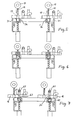
- Figur 3 bis 9 jeweils in Draufsicht die einzelnen Stufen eines Füllvorganges unter Verwendung der erfindungsgemässen Vorrichtung und
- Figur 10 die Ausgestaltung der Zuführung von Granulat der erfindungsgemässen Vorrichtung.
- Eine Vorrichtung zum Füllen von Abstandhalterrahmen 1 für Isolierglasscheiben umfasst zwei von einem nicht näher gezeigten Maschinengestell getragene Bearbeitungsanordnungen 2 und 3. Dabei ist im gezeigten Ausführungsbeispiel die Bearbeitungsanordnung 2 im Maschinengestell ortsfest und die Bearbeitungsanordnung 3 im Maschinengestell horizontal verschiebbar geführt. Oberhalb der Bearbeitungsanordnungen 2 und 3 ist eine Leiste 4 vorgesehen, die Haken 5 aufweist, auf welche ein Abstandhalterrahmen 1 in der Vorrichtung gehängt werden kann, so dass seine Schenkel 6 und 7, die den Bearbeitungsanordnungen 2 bzw. 3 zugeordnet sind, im wesentlichen vertikal ausgerichtet sind.
- Der Aufbau der Bearbeitungsanordnung 2 und 3 wird im folgenden unter Bezugnahme auf die Figuren 1a und 2 am Beispiel der im Maschinengestell ortsfesten Bearbeitungsanordnung 2 erläutert.
- Die Bearbeitungsanordnung 2 besitzt eine mit dem Maschinengestell verbundene Grundplatte 10 und eine an dieser horizontal hin- und herverschiebbar geführten Hilfsplatte 11. Im einzelnen ist die Hilfsplatte 11 an der Grundplatte 10 über eine Führungsschiene 12 abgestützt, wobei im Bereich des unteren Randes 13 der Hilfsplatte 11 beidseitig Führungsrollen 14, die auf der Grundplatte 10 gelagert sind, anliegen. Zur Bewegung der Hilfsplatte 11 gegenüber der Grundplatte 10 ist im gezeigten Ausführungsbeispiel ein Druckmittelmotor 15 vorgesehen.
- An der beweglichen Hilfsplatte 11 ist eine Platte 16 vorgesehen. Diese Platte 16 besitzt ein Loch 17 für den Durchtritt eines Bohrers 18, der an der Grundplatte 10 oder-wie im Ausführungsbeispiel - an der Hilfsplatte 11, quer zur Flächenerstrekkung der Grundplatte 10 bzw. der Hilfsplatte 11 vor- und zurückschiebbar geführt ist. Zum Vor-und Zurückschieben des Bohrers 18 ist ein beispielsweise am Motor 19 für den Bohrer 18 angreifender Druckmittelmotor 20 vorgesehen.
- In der Platte 16 mündet weiters ein Kanal 21 für das Zuführen von Granulat aus. Schliesslich mündet in der Platte 16 ein weiterer Kanal 22 aus, über den eine Masse zugeführt werden kann, mit welcher die in den Schenkeln 6 bzw. 7 des Abstandhalterrahmens 1 erzeugten Einfüllöffnungen nach Beendigung des Füllvorganges wieder verschlossen werden können. Diese Masse ist in einer Kartusche 23 vorrätig gehalten, die vom Kolben eines Druckmittelmotors 24 beaufschlagt werden kann. Dem Kanal 22 ist ein weiterer Kolben 25 zugeordnet, der durch einen Druckmittelmotor 26 vorschiebbar ist. Beim Vorschieben des Kolbens 25 wird die durch die Betätigung des Druckmittelmotors 24 in den Kanal 22 gepresste Menge an Masse aus der Kartusche 23 aus der Mündung 27 des Kanals 22 heraus- und in die im Abstandhalterrahmen erzeugte Einfüllöffnung eingedrückt, um diese zu verschliessen.
- Zum Halten des vertikalen Schenkels 6 des Abstandhalterrahmens 1, der der Bearbeitungsanordnung 2 zugeordnet ist, ist eine Klemmvorrichtung 30 vorgesehen, die von der Grundplatte 10 getragen wird. Die Klemmvorrichtung 30 umfasst einen Anschlag 31 und eine verschwenkbare Klemmbacke 32, die gewinkelt ist und über zwei Schenkel 33 an einem mit der Grundplatte 10 verbundenen Träger 34 um eine im wesentlichen vertikale Achse verschwenkbar gelagert ist. Zur Bestätigung der Klemmbacke 32 ist ein Druckmittelmotor 35 vorgesehen. Bei der in Fig. 1 b gezeigten Ausführungsform der Klemmbacke 32 ist diese einfach gewinkel, d. h. ihre Schenkel 33 stehen senkrecht zu ihrer Druckfläche 36, wobei die Kolbenstange des Druckmittelmotors 35 an einem Ansatz 37 angreift. Eine andere Ausführungsmöglichkeit für die Klemmbacke 32 ist in Figur 1a und den Figuren 3 bis 9 gezeigt. Zwischen den Schenkeln 33 der Klemmbacke 32 ragt ein Druckstempel 40 zur Platte 16 hin, wobei in der Ruhestellung der Bearbeitungsanordnung 2 der Druckstempel 40 die Mündung 41 des Kanals 21, über den Granulat zugeführt werden kann, verschliesst. Der Druckstempel 40 wird mit Hilfe einer Feder 42 vorgedrückt, so dass er, wie aus Figur 1 ersichtlich, gegen eine Seitenfläche des vertikalen Schenkels 6 des Abstandhalterrahmens 1 anliegt und diesen gegen die Platte 16 drückt.
- Dem Druckstempel 40 ist ein Druckmittelmotor 43 zugeordnet, durch welchen der Druckstempel 40 vom Rahmenschenkel 6 bzw. der Platte 16 abgehoben werden kann.
- Der Druckmittelmotor 43 und damit auch der Druckstempel 40 sind über einen Hilfsträger 44 am Träger 34 befestigt und somit starr mit der Grundplatte 10 der Bearbeitungsanordnung 2 verbunden.
- Die bewegliche Bearbeitungsanordnung 3 besitzt einen sinngemässen, teilweise spiegelsymmetrischen Aufbau mit der Massgabe, dass in der Platte 16 der beweglichen Bearbeitungsanordnung 3, die Mündung 41 des Kanals 21 für Granulat, die Mündung 27 des Kanals 22 für die Verschlussmasse und das Loch 17 für den Durchtritt des Bohrers 18 in der gleichen Reihenfolge wie in der Platte 16 der ortsfesten Bearbeitungsanordnung 2 angeordnet sind (vgl. Figur 3 ff. ).
- An den Grundplatten 10 beider Bearbeitungsanordnungen 2 und 3 sind noch Führungsleisten 50 vorgesehen, die in der gleichen Vertikalebene angeordnet sind wie die Vorderflächen der Platten 16, so dass die Schenkel 6 und 7 desAbstandhalterrahmens 1 bei vertikal hängendem Abstandhalterrahmen 1 an den Führungsschienen 50 anliegen. Zusätzlich ist an der beweglichen Bearbeitungsanordnung knapp unter ihrer Klemmvorrichtung 30 eine weitere Führungsleiste 51 vorgesehen, welche von vorne am Schenkel 7 des Abstandhalterrahmens 1 anliegt. Durch diese Führungsleisten 50 und 51 - die Führungsleiste 51 ist bevorzugt an der Hilfsplatte 11 befestigt - wird gewährleistet, dass beim Zustellen der beweglichen Bearbeitungsanordnung 3 der Schenkel 7 des Abstandhalterrahmens 1 ungefähr in der für das Wirksamwerden der Klemmvorrichtung 30 richtigen Lage ist und überdies beim Zustellen der beweglichen Bearbeitungsanordnung mit dieser (beispielsweise mit der Klemmbacke 32 oder der Platte 16) nicht kollidiert.
- Im folgenden wird unter Bezugnahme auf Figur 10 und Figur 2 die Vorrichtung zum Füllen des Abstandhalterrahmens 1 mit Granulat (granulatförmiges, hygroskopisches Material, «Molekularsieb») beschrieben, wobei darauf hinzuweisen ist, dass diese Vorrichtung auch unabhängig von der zuvor beschriebenen Vorrichtung zum Füllen von Abstandhalterrahmen überall dort anwendbar ist, wo Schüttströme von Granulat, insbesondere von abrasivem und leicht zu Staub zerdrückbarem Granulat, gesteuert werden müssen.
- Die Vorrichtung zum Füllen von Hohlkörpern mit Granulat umfasst einen Vorratsbehälter 60 für das Granulat, der über eine Leitung 61 mit einer Austrittsöffnung 41 verbunden ist, wobei die Austrittsöffnung 41 im gezeigten Ausführungsbeispiel in der Platte 16 der Vorrichtung gemäss Figur 1 und 2 vorgesehen ist. Die Mündung 41 der Leitung 61 gegenüberliegend, ist eine Einfüllöffnung 62 im zu füllenden Hohlkörper angeordnet, der im gezeigten Ausführungsbeispiel der Schenkel 6 des Abstandhalterrahmens 1 ist. Der Hohlkörper wird von einem Druckstempel 40 gegen die Platte 16 gedrückt, wobei der Druckstempel 40 bei abgenommenem Hohlkörper die Mündung 41 verschliesst. Dies ist insbesondere bei hygroskopischem Granulat (Molekularsieb), wie es zum Füllen von Abstandhalterrahmen verwendet wird, von Bedeutung. Die Leitung 61 umfasst einen vertikalen Abschnitt 63, einen horizontalen Abschnitt 64 und einen schräg nach oben verlaufenden Abschnitt 65, wobei das der Mündung 41 unmittelbar benachbarte Ende des schräg nach oben verlaufenden Abschnittes 65 im wesentlichen horizontal ausgerichtet ist.
- Aus Figur 10 ist ersichtlich, dass die Abschnitte 63 und 64 der Leitung 61 einen grösseren Querschnitt (Durchmesser) aufweisen als der schräg nach oben verlaufende Abschnitt 65 derselben.
- Der schräg nach oben verlaufende Abschnitt 65 mit kleinerem Querschnitt ist gegenüber dem horizontalen Abschnitt 64 nach oben versetzt, so dass sich im Übergangsbereich der Abschnitte mit grösserem Querschnitt zu dem Abschnitt mit kleinerem Querschnitt in der Leitung 61 eine Stufe 67 ergibt.
- Der Leitung 61 und/oder dem Vorratsbehälter 60 ist ein Schwingungserzeuger zugeordnet, der parallel zum Abschnitt 63 der Leitung 61 ausgerichtete und vorwiegend nach unten wirkende Schwingungshübe erzeugt.
- Zusätzlich oder an Stelle des Schwingungserzeugers kann zum Fördern des Granulates aus dem Vorratsbehälter 60 durch die Leitung 61 eine Vorrichtung zum Erzeugen eines Fördergasstromes, der im Falle von Granulat aus hygroskopischem Material getrocknet ist, zugeordnet sein.
- Der Leitung 61, vorzugsweise dem vertikal verlaufenden Abschnitt 63 derselben ist ein Schüttstromdetektor 68 zugeordnet, der beispielsweise mit Hilfe des Radarprinzips Bewegungen des Granulates durch die Leitung 61 erfasst.
- Sobald der zu füllende Hohlkörper zur Gänze gefüllt ist und kein Granulat mehr durch die Leitung 61 strömt, gibt der Füllstromdetektors, der nun keine Bewegungen des Granulates mehrfeststellt, ein Steuersignal ab, welches den Schwingungserzeuger und/oder die Vorrichtung zum Erzeugen des Fördergasstromes stillsetzt. Hierauf kann der nunmehr mit Granulat gefüllte Hohlkörper abgenommen werden. Da sich das Granulat im Übergangsbereich 66 zwischen den Leitungsabschnitten 63, 64 mit grösserem Querschnitt und dem nach oben gerichteten Abschnitt 65 der Leitung mit kleinerem Querschnitt staut, wenn keine Schwingungen erzeugt oder kein Fördergasstrom durch die Leitung 61 geleitet wird, besteht keine Gefahr, dass bei abgenommenem Hohlkörper Granulat aus dem Vorratsbehälter 60 über die Leitung 61 aus der Mündung 41 austritt. Der Druckstempel 40 hat somit nicht die Aufgabe, das Austreten von Granulat aus der Mündung 41 zu verhindern, sondern dient ausschliesslich dazu, den Hohlkörper gegen die Platte 16 zu drücken und die Mündung gegen Feuchtigkeitszutritt von aussen zu verschliessen.
- Nachstehend wird die Arbeitsweise der in den Figuren 1, 1a und 2 gezeigten Vorrichtung unter Bezugnahme auf die Figuren 3 bis 9 erläutert.
- Zunächst wird ein Abstandhalterrahmen mit seinem oberen horizontalen Schenkel auf den Haken 5 der Hakenleiste 4 aufgehängt. In weiterer Folge wird die bewegliche Bearbeitungsanordnung 3, wie in Figur 3 gezeigt, auf den vertikalen Schenkel 6 des Abstandhalterrahmens 1 hin bewegt, bis die Anschläge 31 der Bearbeitungsanordnungen an den Aussenflächen der vertikalen Schenkel 6 und 7 anliegen. Sobald diese Stellung erreicht ist, werden die Klemmbacken 32 in ihre Wirklage verschwenkt, in der ihre Auflageflächen 36 gegen die Innenflächen der Schenkel 6 und 7 anliegen und vorzugsweise kurz vorher die Druckstempel 40 vorbewegt, damit die Schenkel 6 und 7 des Abstandhalterrahmens 1 gegen die Platten 16 beider Bearbeitungsanordnungen 2 und 3 anliegen (Figur 4).
- In der nun erreichten und in Figur 5 gezeigten Lage sind die vertikalen Schenkel 6 und 7 des Abstandhalterrahmens 1 den Löchern 17 für die Bohrer 18 gegenüberliegend angeordnet, so dass, wie in Figur 6 gezeigt, die Bohrer 18 zum Erzeugen der Einfüllöffnungen im Abstandhalterrahmen 1 tätig werden können.
- Nach Beendigung des Bohrvorganges wird die Hilfsplatte 11 und damit auch die mit ihr verbundene Platte 16 (oder gemäss einer nicht gezeigten Ausführungsform der Abstandhalterrahmen 1 gegenüber der Platte 16) verschoben, so dass die Mündungen 41 der Kanäle (Leitungen 61) für das Zuführen von Granulat den vorher erzeugten Einfüllöchern 62 gegenüberliegen. Nun wird der Schwingungserzeuger in Betrieb gesetzt bzw. ein Fördergasstrom erzeugt, so dass das Granulat aus dem Vorratsbehälter 60 über die Leitung 61 in den Abstandhalterrahmen 1 eintritt (Figur 7).
- Durch erneutes Betätigen der Druckmittelmotore 15 werden nach Beendigung des Füllvorganges, z. B. vom Schüttstromdetektor 68 gesteuert, die Hilfsplatten 11 gegenüber den Grundplatten 10 beider Bearbeitungsanordnungen 2 und 3 einen Schritt weiterbewegt, bis die Mündungen 27 der Kanäle 22 für das Zuführen von Masse aus der Kartusche 23 fluchten (Lage gemäss Figur 8). Nun werden die Druckmittelmotore 24 betätigt, um eine vorgegebene Menge an Masse aus den Kartuschen 23 in den Kanal 22 zu drücken, worauf die Druckmittelmotore 26 die Einpressstempel 25 betätigen, so dass die im Kanal 22 enthaltene Menge an Masse zum Verschliessen der Einfüllöffnungen 62 in den vertikalen Schenkeln 6 und 7 des Abstandhalterrahmens 1 eingedrückt wird. Dabei verhindert der jetzt stillstehende Kolben des Druckmittelmotors 24 ein Rückströmen von Masse aus dem Kanal 22 in die Kartusche 23. Nun werden die Platten 16 durch Betätigen der Druckmittelmotore 15 gegenüber den von den Klemmvorrichtungen 30 gehaltenen Schenkeln 6 und 7 erneut nach rechts oder, wie in Figur 9 gezeigt, nach links verschoben, um die die Einfüllöffnungen 62 verschliessende Masse glatt zu streifen.
- Nach dem Öffnen der Klemmvorrichtungen 30 und dem Zurückziehen der Druckstempel 40 durch Betätigen der Druckmittelmotore 43 kann ein fertig gefüllter Abstandhalterrahmen aus der Vorrichtung entnommen werden. Der soeben beschriebene Arbeitsablauf beim Füllen von Abstandhalterrahmen kann teilweise oder vollständig automatisiert ablaufen, wozu der Vorrichtung nicht gezeigte, die Bewegungen, insbesondere das Zustellen der beweglichen Bearbeitungsanordnung 3 steuernde Endschalter (beispielsweise Lichtschranken u. dgl. ) zugeordnet sind.
- Es ist auch nicht zwingend, dass der Rahmen beim Ausführen des Füllvorganges stillsteht und sich die Platte 16 bewegt, sondern es kann sich auch der Rahmen 1, der von den Klemmvorrichtungen 30 geklemmt ist, gegenüber der Platte 16 hin- und herbewegen.
Claims (23)
Applications Claiming Priority (2)
| Application Number | Priority Date | Filing Date | Title |
|---|---|---|---|
| AT804/85 | 1985-03-18 | ||
| AT0080485A AT383582B (de) | 1985-03-18 | 1985-03-18 | Vorrichtung zum fuellen von hohlkoerpern mit granulat |
Publications (3)
| Publication Number | Publication Date |
|---|---|
| EP0195176A2 EP0195176A2 (de) | 1986-09-24 |
| EP0195176A3 EP0195176A3 (en) | 1987-05-27 |
| EP0195176B1 true EP0195176B1 (de) | 1988-09-14 |
Family
ID=3500087
Family Applications (1)
| Application Number | Title | Priority Date | Filing Date |
|---|---|---|---|
| EP85890144A Expired EP0195176B1 (de) | 1985-03-18 | 1985-06-26 | Vorrichtung zum Füllen von Hohlkörpern mit Granulat |
Country Status (4)
| Country | Link |
|---|---|
| US (1) | US4670954A (de) |
| EP (1) | EP0195176B1 (de) |
| AT (1) | AT383582B (de) |
| DE (2) | DE3564977D1 (de) |
Families Citing this family (15)
| Publication number | Priority date | Publication date | Assignee | Title |
|---|---|---|---|---|
| DE8708488U1 (de) * | 1987-03-09 | 1987-08-13 | Lisec, Peter, Amstetten-Hausmening, Niederösterreich | Verschluß einer Öffnung in einer Hohlprofilleiste |
| AT391682B (de) * | 1987-10-05 | 1990-11-12 | Lisec Peter | Anlage zum foerdern von abstandhalterrahmen fuer isolierglas |
| DE3740922A1 (de) * | 1987-12-03 | 1989-06-22 | Bayer Isolierglasfab Kg | Verfahren und vorrichtung zur herstellung eines abstandhalter-rahmens |
| AT399587B (de) * | 1989-11-27 | 1995-06-26 | Lisec Peter | Schüttgutstromdetektor |
| DK168164B1 (da) * | 1990-12-05 | 1994-02-21 | Skovgaard & Co As | Fremgangsmåde samt apparat til fyldning af en lukket afstandsramme med tørremiddel |
| DE4231683A1 (de) * | 1992-03-31 | 1993-10-07 | Lenhardt Maschinenbau | Verfahren und Vorrichtung zum Herstellen von Abstandshalterrahmen zur Verwendung zwischen den Glastafeln von Isolierglasscheiben |
| AT399501B (de) * | 1993-03-12 | 1995-05-26 | Lisec Peter | Verfahren zum teilweisen füllen von hohlkörpern mit granulat und vorrichtung zur durchführung des verfahrens |
| IT1266114B1 (it) * | 1993-08-02 | 1996-12-20 | For El Base Di Vianello Fortun | Dispositivo per il riempimento di telai distanziatori per vetro-camera con materiale igroscopico |
| AT410066B (de) * | 2000-05-09 | 2003-01-27 | Lisec Peter | Verfahren zum verbinden von hohlprofilleisten durch schweissen |
| ITVE20070034U1 (it) * | 2007-10-16 | 2009-04-17 | Dallan Spa | Dispositivo per l'introduzione di sali disidratanti all'interno di profilati metallici tubolari per vetrocamera. |
| DE102008028010B4 (de) | 2008-06-09 | 2010-04-01 | Bystronic Lenhardt Gmbh | Vorrichtung zum Füllen von Abstandhalterrahmen für Isolierglasscheiben mit einem Trocknungsmittel |
| US8905085B2 (en) | 2011-09-09 | 2014-12-09 | Erdman Automation Corporation | Apparatus for edge sealing and simultaneous gas filling of insulated glass units |
| AT522243B1 (de) | 2019-07-11 | 2020-09-15 | Lisec Austria Gmbh | Verfahren und Vorrichtung zum Füllen von Hohlprofilleisten |
| KR102814070B1 (ko) * | 2022-08-30 | 2025-06-02 | 주식회사 아이지스 | 흡습제 주입기 |
| AT525628B1 (de) | 2022-12-19 | 2023-06-15 | Lisec Austria Gmbh | Verfahren und Vorrichtung zum Füllen von Hohlprofilleisten mit Füllmaterial |
Family Cites Families (7)
| Publication number | Priority date | Publication date | Assignee | Title |
|---|---|---|---|---|
| US3380145A (en) * | 1964-01-08 | 1968-04-30 | Pittsburgh Plate Glass Co | Method of fabricating multiple glazing unit |
| DE2401472C3 (de) * | 1974-01-12 | 1979-03-29 | Karl Lenhardt-Maschinenbau, 7531 Neuhausen | Vorrichtung zum Abfüllen von fließfähigem, körnigem Gut aus einem Vorratsbehälter in Hohlraumprofile mit geringem Querschnitt |
| AT365551B (de) * | 1977-03-02 | 1982-01-25 | Lisec Peter | Vorrichtung zum fuellen rohrfoermiger profile mit koernigem material |
| DE2905841C2 (de) * | 1979-02-15 | 1984-04-19 | Josef Käuferle KG Stahlbau, 8890 Aichach | Verfahren und Anlage zur Herstellung einer Verbundplatte |
| US4279065A (en) * | 1979-10-18 | 1981-07-21 | Sten Sernevi | Machine designed to fill hollow profile rods with a granular material |
| AT383581B (de) * | 1982-04-19 | 1987-07-27 | Lisec Peter | Vorrichtung zum fuellen von abstandhalterrahmen mit hygroskopischem material |
| US4453865A (en) * | 1982-07-21 | 1984-06-12 | Stone & Webster Engineering Corp. | Automatic pressure sensitive regulation assembly |
-
1985
- 1985-03-18 AT AT0080485A patent/AT383582B/de not_active IP Right Cessation
- 1985-06-26 DE DE8585890144T patent/DE3564977D1/de not_active Expired
- 1985-06-26 EP EP85890144A patent/EP0195176B1/de not_active Expired
- 1985-07-02 DE DE8519191U patent/DE8519191U1/de not_active Expired
- 1985-11-27 US US06/802,383 patent/US4670954A/en not_active Expired - Lifetime
Also Published As
| Publication number | Publication date |
|---|---|
| DE3564977D1 (en) | 1988-10-20 |
| EP0195176A3 (en) | 1987-05-27 |
| ATA80485A (de) | 1986-12-15 |
| DE8519191U1 (de) | 1985-08-22 |
| AT383582B (de) | 1987-07-27 |
| EP0195176A2 (de) | 1986-09-24 |
| US4670954A (en) | 1987-06-09 |
Similar Documents
| Publication | Publication Date | Title |
|---|---|---|
| DE2825213C2 (de) | Vorrichtung zum Überführen von Gegenständen aus einer Förderbahn in eine Arbeitsstation | |
| DE1556165C3 (de) | Vorrichtung zur Bewegungssteuerung einzelner Gegenstande auf einem Sam melförderer | |
| EP0195176A2 (de) | Vorrichtung zum Füllen von Hohlkörpern mit Granulat | |
| DE2548197A1 (de) | Sackmagazin | |
| DE3315759A1 (de) | Vorrichtung zur aufnahme von gebirgsankern und deren halterung beim einsetzen auf einem gebirgsankersetzturm | |
| CH674975A5 (de) | ||
| DE3412275C2 (de) | Pulverbeschichtungskabine | |
| DE69700291T2 (de) | Vorrichtung zum Ablängen und Formen von Stahlstäben, insbesondere von Betonbewehrungsstäben | |
| DE10020909B4 (de) | Vorrichtung zur Förderung einer Vorratsrolle | |
| DE2812140A1 (de) | Vorrichtung zum anbringen von schienen-befestigungselementen an schwellen | |
| EP1466829A1 (de) | Anlage zum Füllen von Ventilsäcken | |
| DE3448040C2 (de) | ||
| EP0124763B1 (de) | Vorrichtung zum Einpressen von Möbel-Montageteilen | |
| EP2042436B1 (de) | Vorrichtung zum Zuführen von Verschlussklammern | |
| EP0121704B1 (de) | Müllumschlaganlage mit einem an eine Müllpresse anzuschliessenden Container | |
| DE102023113439A1 (de) | Sackaufstecksystem und Verfahren zum Betreiben | |
| DE4441278A1 (de) | Schnittanordnung zum Schneiden von Teebeuteln aus Bahnmaterialien | |
| EP3449079B1 (de) | Verfahren und vorrichtung zum versiegeln von isolierglas-rohlingen | |
| EP0265783A2 (de) | Vorrichtung zum Speisen von Walzwerken, insbesondere für Ölsaaten | |
| CH432366A (de) | Speicheranordnung | |
| DE3207601C1 (de) | Rohrplattenfuellmaschine | |
| WO1987007239A1 (fr) | Procede pour sceller des emballages en forme de boyau, en particulier des peaux de saucisses, au moyen d'etriers de fermeture en forme de u, ainsi qu'un recipient de stockage et dispositif a cet effet | |
| DE4430562A1 (de) | Vorrichtung und Verfahren zum Fördern von Stückgut auf parallel und drehbar gelagerten Rollen | |
| DE2944266C2 (de) | Speichervorrichtung für ein Montageband | |
| DE7903738U1 (de) | Klemmfreie Flaschenzusammenführung |
Legal Events
| Date | Code | Title | Description |
|---|---|---|---|
| PUAI | Public reference made under article 153(3) epc to a published international application that has entered the european phase |
Free format text: ORIGINAL CODE: 0009012 |
|
| AK | Designated contracting states |
Kind code of ref document: A2 Designated state(s): BE CH DE FR GB IT LI SE |
|
| XX | Miscellaneous (additional remarks) |
Free format text: EIN ANTRAG GEMAESS REGEL 88 EPUE AUF BERICHTIGUNG DER UNTERLAGEN LIEGT VOR. UEBER DIESEN ANTRAG WIRD IM LAUFE DES VERFAHRENS VON DER PRUEFUNGSABTEILUNG EINE ENTSCHEIDUNG GETROFFEN WERDEN. |
|
| ITCL | It: translation for ep claims filed |
Representative=s name: DR. ING. A. RACHELI & C. |
|
| EL | Fr: translation of claims filed | ||
| PUAL | Search report despatched |
Free format text: ORIGINAL CODE: 0009013 |
|
| AK | Designated contracting states |
Kind code of ref document: A3 Designated state(s): BE CH DE FR GB IT LI SE |
|
| 17P | Request for examination filed |
Effective date: 19870416 |
|
| 17Q | First examination report despatched |
Effective date: 19880229 |
|
| ITF | It: translation for a ep patent filed | ||
| GRAA | (expected) grant |
Free format text: ORIGINAL CODE: 0009210 |
|
| AK | Designated contracting states |
Kind code of ref document: B1 Designated state(s): BE CH DE FR GB IT LI SE |
|
| XX | Miscellaneous (additional remarks) |
Free format text: EIN ANTRAG GEMAESS REGEL 88 EPUE AUF BERICHTIGUNG DER UNTERLAGEN LIEGT VOR. UEBER DIESEN ANTRAG WIRD IM LAUFE DES VERFAHRENS VON DER PRUEFUNGSABTEILUNG EINE ENTSCHEIDUNG GETROFFEN WERDEN. |
|
| GBT | Gb: translation of ep patent filed (gb section 77(6)(a)/1977) | ||
| REF | Corresponds to: |
Ref document number: 3564977 Country of ref document: DE Date of ref document: 19881020 |
|
| ET | Fr: translation filed | ||
| PLBE | No opposition filed within time limit |
Free format text: ORIGINAL CODE: 0009261 |
|
| STAA | Information on the status of an ep patent application or granted ep patent |
Free format text: STATUS: NO OPPOSITION FILED WITHIN TIME LIMIT |
|
| 26N | No opposition filed | ||
| ITTA | It: last paid annual fee | ||
| EAL | Se: european patent in force in sweden |
Ref document number: 85890144.0 |
|
| REG | Reference to a national code |
Ref country code: GB Ref legal event code: IF02 |
|
| PGFP | Annual fee paid to national office [announced via postgrant information from national office to epo] |
Ref country code: FR Payment date: 20040610 Year of fee payment: 20 |
|
| PGFP | Annual fee paid to national office [announced via postgrant information from national office to epo] |
Ref country code: SE Payment date: 20040611 Year of fee payment: 20 |
|
| PGFP | Annual fee paid to national office [announced via postgrant information from national office to epo] |
Ref country code: GB Payment date: 20040623 Year of fee payment: 20 |
|
| PGFP | Annual fee paid to national office [announced via postgrant information from national office to epo] |
Ref country code: BE Payment date: 20040713 Year of fee payment: 20 |
|
| PGFP | Annual fee paid to national office [announced via postgrant information from national office to epo] |
Ref country code: CH Payment date: 20040818 Year of fee payment: 20 |
|
| PGFP | Annual fee paid to national office [announced via postgrant information from national office to epo] |
Ref country code: DE Payment date: 20040819 Year of fee payment: 20 |
|
| PG25 | Lapsed in a contracting state [announced via postgrant information from national office to epo] |
Ref country code: GB Free format text: LAPSE BECAUSE OF EXPIRATION OF PROTECTION Effective date: 20050625 |
|
| BE20 | Be: patent expired |
Owner name: *LISEC PETER Effective date: 20050626 |
|
| REG | Reference to a national code |
Ref country code: GB Ref legal event code: PE20 |
|
| REG | Reference to a national code |
Ref country code: CH Ref legal event code: PL |
|
| EUG | Se: european patent has lapsed | ||
| BE20 | Be: patent expired |
Owner name: *LISEC PETER Effective date: 20050626 |
|
| REG | Reference to a national code |
Ref country code: HK Ref legal event code: AM43 Ref document number: 1124340 Country of ref document: HK |