EP0195189A2 - Glocken-Geruchverschluss - Google Patents
Glocken-Geruchverschluss Download PDFInfo
- Publication number
- EP0195189A2 EP0195189A2 EP86100906A EP86100906A EP0195189A2 EP 0195189 A2 EP0195189 A2 EP 0195189A2 EP 86100906 A EP86100906 A EP 86100906A EP 86100906 A EP86100906 A EP 86100906A EP 0195189 A2 EP0195189 A2 EP 0195189A2
- Authority
- EP
- European Patent Office
- Prior art keywords
- bell
- odor trap
- inner part
- trap according
- tubular body
- Prior art date
- Legal status (The legal status is an assumption and is not a legal conclusion. Google has not performed a legal analysis and makes no representation as to the accuracy of the status listed.)
- Granted
Links
Images

Classifications
-
- E—FIXED CONSTRUCTIONS
- E03—WATER SUPPLY; SEWERAGE
- E03C—DOMESTIC PLUMBING INSTALLATIONS FOR FRESH WATER OR WASTE WATER; SINKS
- E03C1/00—Domestic plumbing installations for fresh water or waste water; Sinks
- E03C1/12—Plumbing installations for waste water; Basins or fountains connected thereto; Sinks
- E03C1/28—Odour seals
-
- E—FIXED CONSTRUCTIONS
- E03—WATER SUPPLY; SEWERAGE
- E03F—SEWERS; CESSPOOLS
- E03F5/00—Sewerage structures
- E03F5/04—Gullies inlets, road sinks, floor drains with or without odour seals or sediment traps
- E03F5/0407—Floor drains for indoor use
-
- E—FIXED CONSTRUCTIONS
- E03—WATER SUPPLY; SEWERAGE
- E03F—SEWERS; CESSPOOLS
- E03F5/00—Sewerage structures
- E03F5/04—Gullies inlets, road sinks, floor drains with or without odour seals or sediment traps
- E03F2005/0416—Gullies inlets, road sinks, floor drains with or without odour seals or sediment traps with an odour seal
- E03F2005/0418—Gullies inlets, road sinks, floor drains with or without odour seals or sediment traps with an odour seal in the form of a bell siphon
Definitions
- the invention relates to a bell trap of the type specified in the preamble of claim 1.
- the invention has for its object to simplify the insertion of the bell odor trap when connecting the floor drain, to ensure that the bell odor trap is permanently seated and also to disassemble at any time, e.g. for inspection, cleaning or converting the floor drain.
- the bayonet catch has the advantage that it securely fixes the bell trap with a simple rotary movement that is limited in radians, whereby the insertion of the bell trap on the one hand and the removal on the other are particularly simplified without endangering the permanently tight fit of the bell trap would.
- a bayonet lock is not nearly as vulnerable to overgrowth if the floor drain is used for a long time like fastening screws or screw spindles.
- a bayonet lock has a security against being unscrewed, so that the part cannot come loose on its own.
- an expedient embodiment of the subject matter of the invention in which a tubular inner part and a bell extending over the inner part are provided, can be seen from claim 2.
- the bell which is easily accessible from above, cooperates with the bayonet catch. It also has receptacles for a turning tool so that it can be moved from above without reaching into the tubular body when the bayonet catch is released.
- the measures of claim 4 are also expedient, because with it. a perfect fit and tightening of the odor trap can be achieved when closing the bayonet catch.
- the embodiment of claim 5 is also advantageous because it achieves a desirable suit that ensures the tight fit of the bell odor trap in the tubular body.
- the bayonet catch is particularly stable and resilient if the measures of claim 6 are given.
- the tabs are part of the ribs on the bell, which not only improve the structural strength of the bell, but are also subjected to the forces that have to be introduced into the bell when the bayonet catch is tightened or released.
- the two-part design of the bell odor trap is particularly easy to master in terms of shape, especially if the odor trap is made of plastic. Nevertheless, the installation of the odor trap, even if it is inaccessible in a deep tubular body, is easy because the inner part in the tubular body only needs to be brought into a certain position, before the bell placed over it centers the inner part in this position, clamps it and ensures that the odor trap is held in the operating position. This also has the advantage that after the bayonet catch has been released, the bell can be easily removed and, moreover, the inner part is then freely accessible and just as easily removable, which considerably simplifies the cleaning work.
- the feature of claim 8 is also favorable.
- the inner part also has a sufficiently firm fit in the tubular body and the seal which is essential for an odor trap.
- the feature of claim 9 is also useful, since the holding ribs provide the necessary distance between the inside of the bell and the outside of the inner part and also take over the centering of the inner part.
- the feature of claim 10 is also expedient because it defines a specific end position of the bell on the inner part and the loads from the bell are also transmitted favorably to the inner part.
- the handling of the bell odor trap is particularly simple with a tool according to claim 11. Even in the case of extremely deep-lying tubular bodies in a floor drain, the worker does not need to climb into the shaft or lean in, but can comfortably and safely install or remove the bell odor trap from above by rotating the thorns on the receptacles in the respective direction of rotation attacks, loosens or closes the bayonet lock and lifts the bell with the bayonet lock open.
- the features of claim 13 are important because After removing the bell, the inner part may still be firmly seated in the tube body and can only be easily lifted out by gripping it with the gripping hook.
- a bell trap 1 and 2 show a bell trap 1, which is inserted into a tubular body 2, preferably a base body of a floor drain, not shown, and is fixed therein.
- a shaft attachment part and a further shaft inlet part can be connected to the tubular body 2 at the top, which is connected, for example, to a rain gutter.
- the bell trap 1 is thus significantly below the floor level, i.e. depending on the frost depth up to 1.60 m. Nevertheless, the bell-type odor trap 1 must be inserted and dismantled again, e.g. for maintenance, cleaning or conversion work in the floor drain.
- the tubular body 2 has a downwardly extending pipe socket 3 and on its inner wall a circumferential socket 4 for an edge flange 5 at the lower end of an inner part 9 of the bell odor trap 1.
- the edge flange 5 has a circumferential groove 6 in which a seal 7 is seated, as well as an outwardly reaching, bevelled edge 8, which extends from the upper edge of the socket 4 supports and thus determines the height of the inner part 9 in the tubular body 2. This seat centers the odor trap 1 in its predetermined position.
- the inner part 9 is designed here in the manner of a truncated cone. But it could also be formed by a cylindrical tube.
- the upper edge of the inner part 9, designated 10, is open.
- the lower ends of the ribs 17 terminate in tabs 20 projecting outwards, which have a ramp surface 21 that rises in the circumferential direction to a latching projection 22, to which a support surface 20 ′′ extends up to an end stop 20 ′ which extends through the rib 17
- the support surface 20 ′′ can be designed to rise slightly in the direction of the end stop 20 ′.
- the tabs 20 form elements of a bayonet catch, the counter elements of which are radially projecting projections 23 on the inner wall of the tubular body 2.
- the tabs 20 and the projections 23 are provided with the same circumferential spacings and in the same number and overlapping one another in the radial direction (FIG. 1).
- the inner part 9 is supported in the socket 4 and is centered and fixed by the bell 11, which engages with the tabs 20 under the projections 23 and is held in its operating position.
- the receptacles 19 are expediently used for mounting and dismounting.
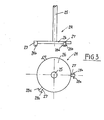
- the tool 24 shown in FIG. 3 is particularly suitable for this purpose, which consists of a handle 25 with a plate 26 fastened to a handle end and of which on spokes 27 projecting in a star shape, on which underneath the plate 26 in both directions of rotation about the axis of the handle 25 protruding spikes 28a and 28b are attached.
- the plate 26 is designed so that it can be placed flat on the bell bottom 12 and remains radially within the ears 18.
- the spikes 28a and 28b are aligned such that they fit into the receptacles 19.
- a gripping hook could be arranged, to which corresponding gripping eyes are assigned on the inside or outside of the inner part 9.
- the rotary tool 24 is placed on the bell bottom 12 and rotated until the spikes 28a or 28b, depending on the direction in which the bayonet lock is released, enter the receptacles 19. Then the bayonet catch is released with a strong rotation and at the same time a slight pressure downwards, so that the bell 11 can be lifted out. This allows free access to the pipe socket 3. If the inner part 9 is also to be lifted out, this can easily be done with the gripping hook at the other end of the stem 25.
- the inner part 9 with the sealing ring 7 is brought into position and pressed into the socket 4 and then the bell 11 is placed over the inner part 9 in the opposite manner and with the help of the rotary tool 24 into the bafonet lock with the tabs 20 and projections 23 rotated, so that the bell 11 is locked and is supported on the inner part 9 and thereby also fixes it.
Landscapes
- Engineering & Computer Science (AREA)
- Health & Medical Sciences (AREA)
- Life Sciences & Earth Sciences (AREA)
- Hydrology & Water Resources (AREA)
- Public Health (AREA)
- Water Supply & Treatment (AREA)
- Environmental & Geological Engineering (AREA)
- Sewage (AREA)
- Pulleys (AREA)
- Glass Compositions (AREA)
- Massaging Devices (AREA)
Abstract
Description
- Die Erfindung betrifft einen Glocken-Geruchverschluß der im Gattungsbegriff des Patentanspruchs 1 angegebenen Art.
- Bekannte Glocken-Geruchverschlüsse einteiliger Bauart werden mit mehreren Schrauben befestigt, die insbesondere bei tief in den Boden eingesetzten Bodenabläufen schwer anzuziehen und nach längerer Benutzungsdauer außerordentlich schwer und mühsam wieder zu lösen sind. Es ist auch bekannt, den Glocken-Geruchverschluß in einteiliger Ausführung mit einer Spindel von oben in der Betriebslage zu sichern. Diese Maßnahrne ist jedoch außerordentlich aufwendig. Schließlich ist es auch bekannt, einen einteiligen Glocken-Geruchverschluß durch einen Schachtdeckel oder einen Vorsprung zu si- . chern, was jedoch bei tief liegenden Ablaufrohrkörpern nicht möglich ist.
- Der Erfindung liegt die Aufgabe zugrunde, das Einsetzen des Glokken-Geruchverschlusses beim Anschließen des Bodenablaufes zu vereinfachen, für einen dauerhaft festen Sitz des Glocken-Geruchverschlusses zu sorgen und auch jederzeit die Demontage, z.B. zur Inspektion, zur Reinigung oder zum Umbauen des Bodenablaufes, zu ermöglichen.
- Die gestellte Aufgabe wird erfindungsgemäß durch die im kennzeichnenden Teil des Patentanspruchs 1 angegebenen Merkmale gelöst.
- Der Bajonettverschluß hat den Vorteil, daß er den Glocken-Geruchverschluß mit einer einfachen und im Bogenmaß begrenzten Drehbewegung sicher festlegt, wodurch das Einsetzen des Glocken-Geruchverschlusses einerseits und das Herausnehmen andererseits besonders vereinfacht sind, ohne daß der dauerhaft feste Sitz des Glokken-Geruchverschlusses gefährdet wäre. Ein Bajonettverschluß ist auch gegen Zuwachsen bei längerer Benutzung des Bodenablaufes bei weitem nicht so gefährdet wie Befestigungsschrauben oder Schraubspindeln. Schließlich weist ein Bajonettverschluß eire Sicherung gegen ein Aufdrehen auf, so daß das Teil sich nicht selbständig lösen kann.
- Eine zweckmäßige Ausführungsform des Erfindungsgegenstandes, bei der ein rohrförmiger Innenteil und eine über den Innenteil greifende Glocke vorgesehen sind, geht aus Anspruch 2 hervor. Hierbei arbeitet vorteilhafterweise die von oben gut zugängliche Glocke mit dem Bajonettverschluß zusammen. Sie besitzt zudem Aufnahmen für ein Drehwerkzeug, so daß sie auch von weiter oben ohne in den Rohrkörper zu greifen, beim Lösen des Bajonettverschlusses bewegt wer- den kann.
- Eine baulich einfache und formentechnisch gut beherrschbare Ausführungsform, insbesondere bei einer Fertigung des Geruchverschlusses aus Kunststoff, geht aus Anspruch 3 hervor.
- Zweckmäßig sind auch die Maßnahmen von Anspruch 4, weil damit. ein einwandfreier Sitz und ein Anziehen des Geruchverschlusses beim Schließen des Bajonettverschlusses erreichbar sind.
- Vorteilhaft ist auch die Ausführungsform von Anspruch 5, weil dadurch ein wünschenswerter Anzug erreicht wird, der für den dichten Sitz des Glocken-Geruchverschlusses im Rohrkörper sorgt.
- Der Bajonettverschluß wird besonders stabil und belastbar, wenn die Maßnahmen von Anspruch 6 gegeben sind. Denn bei dieser Ausbil- dung sind die Laschen Teil der Rippen an der Glocke, die nicht nur die Gestaltfestigkeit der Glocke verbessern, sondern auch gleichzeitig mit den Kräften belastet werden, die beim Anziehen oder Lösen des Bajonettverschlusses in die Glocke einzuleiten sind.
- Eine besonders wichtige Ausführungsform geht aus Anspruch 7 hervor. Die zweigeteilte Ausführung des Glocken-Geruchverschlusses ist formentechnisch besonders einfach zu beherrschen, insbesondere wenn der Geruchverschluß aus Kunststoff gefertigt wird. Trotzdem ist die Anbringung des Geruchverschlusses, auch bei unzugänglicher Lage in einem tiefliegenden Rohrkörper, einfach, weil der Innenteil im Rohrkörper nur in eine bestimmte Lage gebracht zu werden braucht, ehe die darüber gesetzte Glocke den Innenteil in dieser Lage zentriert, festspannt und für die Halterung des Geruchverschlusses in der Betriebslage sorgt. Dies hat auch den Vorteil, daß nach einem Lösen des Bajonettverschlusses die Glocke leicht herausgenommen werden kann und zudem der Innenteil dann frei zugänglich und ebenso leicht herausnehmbar ist, wodurch die Reinigungsarbeiten wesentlich erleichtert werden.
- Formentechnisch günstig ist auch das Merkmal von Anspruch 8. Damit erhält der Innenteil auch den ausreichend festen Sitz im Rohrkörper und die für einen Geruchverschluß unabdingbare Abdichtung.
- Zweckmäßig ist ferner das Merkmal von Anspruch 9, da die Halterippen für den notwendigen Abstand zwischen der Innenseite der Glocke und der Außenseite des Innenteiles sorgen und auch die Zentrierung des Innenteils übernehmen.
- Zweckmäßig ist auch das Merkmal von Anspruch 10, weil damit eine bestimmte Endlage der Glocke auf dem Innenteil festgelegt wird und auch die Belastungen von der Glocke auf den Innenteil günstig übertragen werden.
- Die Handhabung des Glocken-Geruchverschlusses ist mit einem Werkzeug gemäß Anspruch 11 besonders einfach. Auch bei extrem tiefliegenden Rohrkörper in einem Bodenablauf braucht der Arbeiter -nicht in den Schacht zu klettern oder sich hineinzubeugen, sondern er kann von oben bequem und sicher den Glocken-Geruchverschluß einbauen oder demontieren, indem er in der jeweiligen Drehrichtung mit den Dornen an den Aufnahmen angreift, den Bajonettverschluß löst oder schließt und bei offenem Bajonettverschluß die Glocke heraushebt.
- Baulich einfach ist der Gedanke von Anspruch 12, weil dies ein robustes Werkzeug schafft.
- Schließlich sind auch die Merkmale von Anspruch 13 wichtig, weil nach dem Entfernen der Glocke der Innenteil ggfs. noch fest im Rohrkörper sitzt und nur durch Angreifen mit dem Greifhaken leicht herausgehoben werden kann.
- Anhand der Zeichnungen wird nachstehend ein Glocken-Geruchverschluß erläutert.
-
- Fig. 1 einen Längsschnitt durch einen eingesetzten Glocken-Geruchverschluß,
- Fig. 2 einen Horizontalschnitt durch den Rohrkörper, in den der Geruchverschluß eingesetzt ist, mit einer Draufsicht auf den Geruchverschluß und
- Fig. 3 ein Werkzeug zum Anbringen und Demontieren des Geruchverschlusses gemäß den Fig. 1 und 2.
- Aus den Fig. 1 und 2 geht ein Glocken-Geruchverschluß 1 hervor, der in einen Rohrkörper 2, vorzugsweise eines Grundkörpers eines nicht näher dargestellten Bodenablaufes eingesetzt und darin festgelegt ist. An den Rohrkörper 2 kann sich oben ein Schachtaufsatz- teil und ein weiterer Schachteinlaufteil anschließen, der beispielsweise an eine Regenablaufrinne angeschlcssen ist. Der Glocken-Geruchverschluß 1 liegt damit erheblich unter dem Bodenniveau, d.h. in Abhängigkeit von der Frosttiefe bis zu 1,60 m. Trotzdem muß der Glocken-Geruchverschluß 1 nachträglich eingesetzt und auch wieder demontiert werden können, z.B. für Wartungs-, Reinigungs- oder Umbauarbeiten im Bodenablauf.
- Der Rohrkörper 2 besitzt einen nach unten weiterführenden Rohrstutzen 3 und an seiner Innenwand eine umlaufende Fassung 4 für einen Randflansch 5 am unteren Ende eines Innenteils 9 des Glocken-Geruchverschlusses 1. Der Randflansch 5 besitzt eine umlaufende Nut 6, in der eine Dichtung 7 sitzt, sowie einen nach außen greifenden, abgeschrägten Rand 8, der sich am oberen Rand der Fassung 4 abstützt und somit die Höhenlage des Innenteils 9 im Rohrkörper 2 mitbestimmt. Durch diesen Sitz zentriert sich der Geruchverschluß 1 in seine vorbestimmte Lage. Der Innenteil 9 ist hier nach Art eines Kegelstumpfes ausgebildet. Er könnte aber auch von einem zylindrischen Rohr gebildet werden. Der mit 10 bezeichnete obere Rand des Innenteils 9 ist offen.
- Über den nach oben offenen Innenteil 9 greift eine Glocke 11, die sich auf dem oberen Rand 10 und der Außenwandung des Innenteils 9 abstützt. Sie weist einen ebenen Glockenboden 12 auf und an der Innenwand der Glocke 11 sind vertikal verlaufende Halterippen 13 vorgesehen, die oben mit Stützschultern 14 in zur Versteifung dienende niedrige Querrippen 15 übergeführt sind. Mit diesen Stütz- schultern 14 und den Halterippen 13 stützt sich die Glocke 11 auf dem Innenteil 9 ab, wobei die Halterippen 13 den gleichmäßigen Durchgang rings um den Innenteil 9 gewähren. Auf der mit 16 bezeichneten Außenseite der Glocke 11 sind z.B. drei vertikal verlaufende Stützrippen 17 angeformt, die oben in oberhalb des Glockenbodens 12 liegenden Ohren 18 enden, die Aufnahmen 19 in Form tangential verlaufender Bohrungen enthalten.
- Die unteren Enden der Rippen 17 laufen in nach außen vorstehenden Laschen 20 aus, die eine in Umfangsrichtung ansteigende Auflauf- fläche 21 zu einem Rastvorsprung 22 aufweisen, an den sich eine Stützfläche 20" bis zu einem Endanschlag 20' erstreckt, der durch die Rippe 17 gebildet wird. Die Stützfläche 20" kann in Richtung zum Endanschlag 20' leicht ansteigend ausgestaltet sein. Die Laschen 20 bilden Elemente eines Bajonettverschlusses, dessen Gegenelemente radial einspringende Vorsprünge 23 an der Innenwand des Rohrkörpers 2 sind. Die Laschen 20 und die Vorsprünge 23 sind mit gleichen Umfangsabständen und in gleicher Anzahl und in radialer Richtung einander überlappend (Fig. 1) vorgesehen. Der Innenteil 9 stützt sich in der Fassung 4 ab und wird durch die Glocke 11 zentriert und festgelegt, die mit den Laschen 20 unter die Vorsprünge 23 greift und in ihrer Betriebslage festgehalten wird.
- Wenn sich der Glocken-Geruchverschluß 1 in einem tiefen Rohrkörper 2 befindet, weil er beispielsweise unter der Frostgrenze angeordnet sein soll und zu dem von oben wegen der Tiefe nur schwer Zugang besteht, werden zweckmäßigerweise die Aufnahmen 19 zum Montieren und Demontieren verwendet. Besonders geeignet ist dazu das in Fig. 3 dargestellte Werkzeug 24, das aus einem Stiel 25 mit einer an einem Stielende befestigten Platte 26 und davon auf sternförmig abstehenden Speichen 27 besteht, an denen unterhalb der Platte 26 in beiden Drehrichtungen um die Achse des Stieles 25 vorstehende Dornen 28a und 28b befestigt sind. Die Platte 26 ist so ausgebildet, daß sie sich plan auf den Glockenboden 12 setzen läßt und radial innerhalb der Ohren 18 bleibt. Die Dornen 28a und 28b sind derart ausgerichtet, daß sie in die Aufnahmen 19 passen.
- Am anderen nicht gezeigten Ende des Stieles 25 könnte ein Greifhaken angeordnet sein, dem an der Innen- oder Außenseite des Innenteiles 9 entsprechende Greifösen zugeordnet sind.
- Das Drehwerkzeug 24 wird bei eingesetztem Glocken-Geruchverschluß 1 gemäß Fig. 1 oben auf den Glockenboden 12 aufgelegt und verdreht, bis die Dornen 28a oder 28b, je nach Löserichtung des Bajo- nettverschlusses, in die Aufnahmen 19 eintreten. Dann wird mit einer kräftigen Drehung und gleichzeitig einem leichten Druck nach unten der Bajonettverschluß gelöst, so daß die Glocke 11 herausgehoben weiden kann. Damit ist freier Zugarg zum Rohrstutzen 3 möglich. Soll auch der Innenteil 9 herausgehoben werden, so kann mit dem Greifhaken am anderen Ende des Stiels 25 dies leicht durchgeführt werden.
- Beim Einbringen des Geruchverschlusses wird zunächst der Innenteil 9 mit dem Dichtring 7 in Lage gebracht und in die Fassung 4 eingedrückt und dann in umgekehrter Weise die Glocke 11 über den Innenteil 9 gestülpt und mit Hilfe des Drehwerkzeuges 24 in den Bafonettverschluß mit den Laschen 20 und Vorsprüngen 23 gedreht, so daß die Glocke 11 verriegelt festsitzt und sich auf dem Innenteil 9 abstützt und diesen dadurch ebenfalls festlegt.
Claims (13)
Priority Applications (1)
| Application Number | Priority Date | Filing Date | Title |
|---|---|---|---|
| AT86100906T ATE35163T1 (de) | 1985-03-16 | 1986-01-23 | Glocken-geruchverschluss. |
Applications Claiming Priority (2)
| Application Number | Priority Date | Filing Date | Title |
|---|---|---|---|
| DE3509528 | 1985-03-16 | ||
| DE19853509528 DE3509528A1 (de) | 1985-03-16 | 1985-03-16 | Glocken-geruchverschluss |
Publications (4)
| Publication Number | Publication Date |
|---|---|
| EP0195189A2 true EP0195189A2 (de) | 1986-09-24 |
| EP0195189A3 EP0195189A3 (en) | 1987-04-15 |
| EP0195189B1 EP0195189B1 (de) | 1988-06-15 |
| EP0195189B2 EP0195189B2 (de) | 1992-02-19 |
Family
ID=6265427
Family Applications (1)
| Application Number | Title | Priority Date | Filing Date |
|---|---|---|---|
| EP86100906A Expired - Lifetime EP0195189B2 (de) | 1985-03-16 | 1986-01-23 | Glocken-Geruchverschluss |
Country Status (3)
| Country | Link |
|---|---|
| EP (1) | EP0195189B2 (de) |
| AT (1) | ATE35163T1 (de) |
| DE (2) | DE3509528A1 (de) |
Cited By (4)
| Publication number | Priority date | Publication date | Assignee | Title |
|---|---|---|---|---|
| WO2006085010A1 (fr) * | 2005-02-11 | 2006-08-17 | Raccords Et Plastiques Nicoll | Bac a sable pour caniveaux |
| DE10201287C5 (de) * | 2002-01-15 | 2009-02-19 | Aco Severin Ahlmann Gmbh & Co. Kg | Bodenablauf |
| EP1453574B1 (de) * | 2001-12-12 | 2009-04-29 | Aco Severin Ahlmann GmbH & Co. KG | Brandschutzablauf |
| US7636957B2 (en) | 2005-08-30 | 2009-12-29 | Zurn Industries, Llc | Urinal |
Families Citing this family (2)
| Publication number | Priority date | Publication date | Assignee | Title |
|---|---|---|---|---|
| DE3639285C2 (de) * | 1986-11-18 | 1995-11-09 | Bernhard Kessel | Bodenablauf |
| AT393397B (de) * | 1988-06-06 | 1991-10-10 | Hutterer & Lechner Kg | Ablauf mit einem wassergeruchsverschlusseinsatz |
Family Cites Families (8)
| Publication number | Priority date | Publication date | Assignee | Title |
|---|---|---|---|---|
| DE221835C (de) * | 1900-01-01 | |||
| FR318888A (fr) * | 1902-02-20 | 1902-10-29 | Blanc | Récepteur avec siphon démontable |
| DE2329463A1 (de) * | 1972-06-09 | 1973-12-20 | Weegels Hamers Maria Johanna B | Abzugsgrube |
| DE2233552C3 (de) * | 1972-07-07 | 1978-10-12 | Noriatsu Nagoya Aichi Kojima (Japan) | Bodenablauf |
| DE2507045A1 (de) * | 1975-02-19 | 1976-09-09 | Dallmer Helmuth Fa | Dacheinlauf |
| DE7710485U1 (de) * | 1977-04-02 | 1977-08-04 | Passavant-Werke Michelbacher Huette, 6209 Aarbergen | Boden- oder deckenablauf |
| DE2808711A1 (de) * | 1978-03-01 | 1979-09-06 | Dallmer Helmuth Fa | Aus kunststoffteilen zusammensetzbarer bodenablauf mit geruchsverschluss |
| DE3025637A1 (de) * | 1980-07-07 | 1982-04-22 | Passavant-Werke Michelbacher Hütte, 6209 Aarbergen | Bodenablauf mit geruchverschluss |
-
1985
- 1985-03-16 DE DE19853509528 patent/DE3509528A1/de not_active Withdrawn
-
1986
- 1986-01-23 AT AT86100906T patent/ATE35163T1/de not_active IP Right Cessation
- 1986-01-23 EP EP86100906A patent/EP0195189B2/de not_active Expired - Lifetime
- 1986-01-23 DE DE8686100906T patent/DE3660314D1/de not_active Expired
Cited By (5)
| Publication number | Priority date | Publication date | Assignee | Title |
|---|---|---|---|---|
| EP1453574B1 (de) * | 2001-12-12 | 2009-04-29 | Aco Severin Ahlmann GmbH & Co. KG | Brandschutzablauf |
| DE10201287C5 (de) * | 2002-01-15 | 2009-02-19 | Aco Severin Ahlmann Gmbh & Co. Kg | Bodenablauf |
| WO2006085010A1 (fr) * | 2005-02-11 | 2006-08-17 | Raccords Et Plastiques Nicoll | Bac a sable pour caniveaux |
| FR2882069A1 (fr) * | 2005-02-11 | 2006-08-18 | Nicoll Raccords Plastiques | Bac a sable pour caniveaux |
| US7636957B2 (en) | 2005-08-30 | 2009-12-29 | Zurn Industries, Llc | Urinal |
Also Published As
| Publication number | Publication date |
|---|---|
| DE3509528A1 (de) | 1986-09-25 |
| ATE35163T1 (de) | 1988-07-15 |
| EP0195189B1 (de) | 1988-06-15 |
| DE3660314D1 (en) | 1988-07-21 |
| EP0195189B2 (de) | 1992-02-19 |
| EP0195189A3 (en) | 1987-04-15 |
Similar Documents
| Publication | Publication Date | Title |
|---|---|---|
| DE69703235T2 (de) | Vorrichtung zur Herstellung eines Getränkes | |
| EP0443145B1 (de) | Blumentopfanordnung | |
| EP0959978A1 (de) | Filter | |
| DE2601319A1 (de) | An einem pfosten, insbesondere dem haltestellenpfosten einer autobus- oder einer strassenbahnlinie, anbringbarer informationskasten | |
| DE3690048C2 (de) | Selbstsperrender Mannloch-Deckel | |
| EP0195189B1 (de) | Glocken-Geruchverschluss | |
| DE2501435A1 (de) | Vorrichtung zum verriegeln eines deckels eines strassenschachtes | |
| AT396698B (de) | Drehgriff an einer ab- und überlaufeinrichtung für eine wanne | |
| DE202017100539U1 (de) | Schachtabdeckung | |
| DE102015005321B4 (de) | Getränkeschutzvorrichtung | |
| DE2501434C3 (de) | Abdeckung fur einen Einstiegschacht | |
| DE7533387U (de) | Verschlussteil fuer reinigungsoeffnungen | |
| EP3231674B1 (de) | Wasch-, pflege- und/oder trocknungswalze | |
| EP3272954B1 (de) | Ablaufanordnung | |
| EP0231454B1 (de) | Schachtabdeckung | |
| DE20220825U1 (de) | Halterung zum Befestigen eines Schutzkorbs am Schaft eines Bootsaußenbordmotors | |
| DE3233802A1 (de) | Abnehmbare abdeckkappe, insbesondere fuer die felge eines kraftfahrzeugrades | |
| EP3173540B1 (de) | Baugruppe zum verschliessen einer ablauföffnung eines beckens und verfahren zum montieren einer solchen baugruppe | |
| DE3416571A1 (de) | Halteelement, insbesondere zur befestigung einer verkleidungsplatte an einer traegerplatte | |
| DE1784994C3 (de) | Schachtabdeckung | |
| DE8318635U1 (de) | An einer wand befestigbare einstieghilfe | |
| DE102018005962A1 (de) | Unterflur-Schacht insbesondere für die Energieverteilung und/oder die Telekommunikation | |
| DE8708111U1 (de) | Absperrpoller | |
| DE10237569A1 (de) | Absicherung für Deckelverschlüsse | |
| DE3039790C2 (de) | Nach Art eines Renkverschlusses ausgebildete Schachtabdeckung |
Legal Events
| Date | Code | Title | Description |
|---|---|---|---|
| PUAI | Public reference made under article 153(3) epc to a published international application that has entered the european phase |
Free format text: ORIGINAL CODE: 0009012 |
|
| AK | Designated contracting states |
Kind code of ref document: A2 Designated state(s): AT BE CH DE FR GB IT LI NL SE |
|
| PUAL | Search report despatched |
Free format text: ORIGINAL CODE: 0009013 |
|
| AK | Designated contracting states |
Kind code of ref document: A3 Designated state(s): AT BE CH DE FR GB IT LI NL SE |
|
| 17P | Request for examination filed |
Effective date: 19870406 |
|
| 17Q | First examination report despatched |
Effective date: 19871125 |
|
| GRAA | (expected) grant |
Free format text: ORIGINAL CODE: 0009210 |
|
| AK | Designated contracting states |
Kind code of ref document: B1 Designated state(s): AT BE CH DE FR GB IT LI NL SE |
|
| PG25 | Lapsed in a contracting state [announced via postgrant information from national office to epo] |
Ref country code: IT Free format text: LAPSE BECAUSE OF FAILURE TO SUBMIT A TRANSLATION OF THE DESCRIPTION OR TO PAY THE FEE WITHIN THE PRE;WARNING: LAPSES OF ITALIAN PATENTS WITH EFFECTIVE DATE BEFORE 2007 MAY HAVE OCCURRED AT ANY TIME BEFORE 2007. THE CORRECT EFFECTIVE DATE MAY BE DIFFERENT FROM THE ONE RECORDED.SCRIBED TIME-LIMIT Effective date: 19880615 Ref country code: GB Free format text: LAPSE BECAUSE OF NON-PAYMENT OF DUE FEES Effective date: 19880615 Ref country code: BE Effective date: 19880615 Ref country code: FR Effective date: 19880615 Ref country code: NL Effective date: 19880615 |
|
| REF | Corresponds to: |
Ref document number: 35163 Country of ref document: AT Date of ref document: 19880715 Kind code of ref document: T |
|
| PG25 | Lapsed in a contracting state [announced via postgrant information from national office to epo] |
Ref country code: SE Effective date: 19880630 |
|
| REF | Corresponds to: |
Ref document number: 3660314 Country of ref document: DE Date of ref document: 19880721 |
|
| EN | Fr: translation not filed | ||
| NLV1 | Nl: lapsed or annulled due to failure to fulfill the requirements of art. 29p and 29m of the patents act | ||
| GBV | Gb: ep patent (uk) treated as always having been void in accordance with gb section 77(7)/1977 [no translation filed] | ||
| PG25 | Lapsed in a contracting state [announced via postgrant information from national office to epo] |
Ref country code: AT Effective date: 19890123 |
|
| PG25 | Lapsed in a contracting state [announced via postgrant information from national office to epo] |
Ref country code: LI Effective date: 19890131 Ref country code: CH Effective date: 19890131 |
|
| PLBI | Opposition filed |
Free format text: ORIGINAL CODE: 0009260 |
|
| 26 | Opposition filed |
Opponent name: PASSAVANT-WERKE AG Effective date: 19890310 |
|
| REG | Reference to a national code |
Ref country code: CH Ref legal event code: PL |
|
| PUAH | Patent maintained in amended form |
Free format text: ORIGINAL CODE: 0009272 |
|
| STAA | Information on the status of an ep patent application or granted ep patent |
Free format text: STATUS: PATENT MAINTAINED AS AMENDED |
|
| 27A | Patent maintained in amended form |
Effective date: 19920219 |
|
| AK | Designated contracting states |
Kind code of ref document: B2 Designated state(s): AT BE CH DE FR GB IT LI NL SE |
|
| EN3 | Fr: translation not filed ** decision concerning opposition | ||
| PGFP | Annual fee paid to national office [announced via postgrant information from national office to epo] |
Ref country code: DE Payment date: 20020131 Year of fee payment: 17 |
|
| PG25 | Lapsed in a contracting state [announced via postgrant information from national office to epo] |
Ref country code: DE Free format text: LAPSE BECAUSE OF NON-PAYMENT OF DUE FEES Effective date: 20030801 |