EP0195215B1 - Flachlege- und Abzugsvorrichtung für im Blasverfahren hergestellte Kunststoffschlauchfolienbahnen - Google Patents
Flachlege- und Abzugsvorrichtung für im Blasverfahren hergestellte Kunststoffschlauchfolienbahnen Download PDFInfo
- Publication number
- EP0195215B1 EP0195215B1 EP86101458A EP86101458A EP0195215B1 EP 0195215 B1 EP0195215 B1 EP 0195215B1 EP 86101458 A EP86101458 A EP 86101458A EP 86101458 A EP86101458 A EP 86101458A EP 0195215 B1 EP0195215 B1 EP 0195215B1
- Authority
- EP
- European Patent Office
- Prior art keywords
- rollers
- take
- flat laying
- turning bars
- deflecting
- Prior art date
- Legal status (The legal status is an assumption and is not a legal conclusion. Google has not performed a legal analysis and makes no representation as to the accuracy of the status listed.)
- Expired - Lifetime
Links
- 239000004033 plastic Substances 0.000 title abstract description 3
- 229920003023 plastic Polymers 0.000 title abstract description 3
- 238000010096 film blowing Methods 0.000 claims abstract 2
- 238000001125 extrusion Methods 0.000 claims description 5
- 239000002985 plastic film Substances 0.000 claims description 2
- 229920006255 plastic film Polymers 0.000 claims description 2
- 230000007423 decrease Effects 0.000 claims 1
- 238000006073 displacement reaction Methods 0.000 claims 1
- 230000000717 retained effect Effects 0.000 abstract 1
- 238000004804 winding Methods 0.000 description 8
- 238000000034 method Methods 0.000 description 4
- 239000000969 carrier Substances 0.000 description 2
- 238000003780 insertion Methods 0.000 description 2
- 230000037431 insertion Effects 0.000 description 2
- 238000000071 blow moulding Methods 0.000 description 1
- 230000003247 decreasing effect Effects 0.000 description 1
- 238000004519 manufacturing process Methods 0.000 description 1
Images

Classifications
-
- B—PERFORMING OPERATIONS; TRANSPORTING
- B29—WORKING OF PLASTICS; WORKING OF SUBSTANCES IN A PLASTIC STATE IN GENERAL
- B29C—SHAPING OR JOINING OF PLASTICS; SHAPING OF MATERIAL IN A PLASTIC STATE, NOT OTHERWISE PROVIDED FOR; AFTER-TREATMENT OF THE SHAPED PRODUCTS, e.g. REPAIRING
- B29C53/00—Shaping by bending, folding, twisting, straightening or flattening; Apparatus therefor
- B29C53/02—Bending or folding
- B29C53/10—Bending or folding of blown tubular films, e.g. gusseting
Definitions
- the invention relates to a lay-flat and take-off device for plastic tubular film webs produced by the blow-molding process from a fixedly arranged film blow head, the flat lay plates and squeeze rollers of which can be reversibly pivoted about at least approximately 360 ° about the axis of the supplied film tube, with the flat lay plates and squeeze rolls on the one hand and the stationary pair of preferential rolls on the other hand at least two deflecting rollers for deflecting the web by approximately 180 ° and two turning bars for deflecting the web by approximately 180 ° with simultaneous change of direction one behind the other and alternately mounted on supports which can be pivoted relative to one another about the axis of rotation of the flat laying plates in such a way that the axes of the deflecting rollers and the turning rods extend tangentially to circles around the axis of rotation of the flat sheets, the deflection rollers being radially outside the part wrapped by the web in every possible operating position e of the turning bars, the pivoting angle of the deflecting rollers
- devices of this type known from US Pat. No. 3,768,949 serve to distribute thick spots in the tubular film web when it is rolled up in the manner of cable winding, so that cylindrical winding rolls can be produced.
- the known devices there are considerable difficulties in guiding the extruded front end of the tubular film web through the squeeze rolls after the blown film line has been started up, and then in a zigzag shape between the deflection rolls and turning bars and over the take-off rolls to the winding device.
- This insertion process is particularly difficult and requires considerable skill on the part of the operators because a molten and then soft-plastic film tube, which tends to stick, is constantly being fed out of the extrusion ring die.
- the object of the invention is therefore to provide a lay-flat and take-off device of the type specified at the beginning, through which the front end of the extruded tubular film web can be passed more easily when the blown film system is started up.
- this object is achieved in that the carriers have approximately equal-length lateral arms between which the deflecting rollers and turning bars are mounted, and in that the deflecting rollers and turning bars in guides of the arms can be moved from the outside in or from the inside out and in their inner and outer positions can be locked.
- the turning bars in the device according to the invention are moved outwards and the deflection rolls inwards, so that the front end of the extruded tubular film web can be passed straight between them.
- the device according to the invention not only makes it much easier to pull in the front end of the tubular film web when starting up the blown film system, it also significantly reduces the amount of rejects that would otherwise occur.
- Drives for example spindle drives, can be provided to move the deflecting rollers and turning bars or their bearings in the guides.
- the bearings of the upper turning bar can expediently be provided with swiveling levers, between the end regions of which a support roller is rotatably mounted.
- the roller reduces the friction of the tubular film web, which is otherwise pulled over the turning bar.
- the support roller can be pivoted into its inactive position between the lateral arms before the turning bar is moved back into its inner operating position.
- one coil each is releasably held between these and outside of the take-off rollers for the purpose of throwing off, pulling strips being wound onto the coils, which are connected between the coils.
- the inner spool is thrown between the turning rods moved outwards and the deflecting rollers pushed inwards and passed through the nip of the squeezing rollers, so that the front end of the wound-up drawstring can be connected to the front end of the just extruded tubular film web.
- the other spool is thrown onto the floor in the area of the winding device, so that the front end of the extruded tubular film web can be pulled in by simply pulling on the drawstring.
- a row of spools can be ejectably held in a cassette-like magazine.
- One of the squeeze rollers is expediently arranged so that it can be moved away from the other, so that the spool can also be passed between the squeeze rollers in a simple manner.
- the slide is expediently provided with side walls to form a collecting funnel.
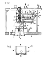
- the frame 1 of the lay-flat and take-off device is fastened to a false ceiling 2 of the manufacturing building, the false ceiling 2 being provided with an opening 3 for the frame 4 of the lay-flat device 5, which is arranged perpendicularly above the annular extrusion nozzle of the blown film extruder, not shown.
- the frame 4 of the lay-flat device 5, together with the squeeze rollers 6, 7, is pivotably mounted about 360 ° about the axis 8 of the tubular film supplied.
- the supports 10, 12 of the turning bars 13, 14 and the supports 11 for the deflection roller 15 are pivotably mounted on the vertical pivot shaft 9, to which the frame 4 of the lay-flat and pull-off device is connected.
- the arms 16 of the deflection roller 17 are connected directly to the frame 4 so that they pivot with it.
- lay-flat and take-off device according to FIGS. 1 and 2 corresponds to that described in US Pat. No. 3,768,949, so that reference is made to these for further explanation.
- the basic difference between the device known from US Pat. No. 3,768,949 and the lay-flat and pull-off device according to FIGS. 1 and 2 is that the carriers 10, 11, 12 and the frame 4 have approximately equal length lateral arms 16, 18, 19, 20 are provided, between which the turning bars 14 and 13 and the deflecting rollers 15, 17 are held or supported.
- the side arms 16, 18, 19, 20 are provided with longitudinal guide grooves 21, 22, 23, 24, in which the bearings for the deflecting rollers 15, 17 and the brackets for the turning bars 13, 14 are guided in a longitudinally displaceable manner.
- the turning bars 13, 14 are non-rotatably supported in their holders, while the deflecting rollers 15, 17 are rotatably mounted.
- two cassette-like magazines 25, 26 are arranged on the machine frame, in which a plurality of coils 29, 30 are held on pins 27, 28, which can also consist of retractable piston rods.
- the cassette 25 is arranged between the turning bars and deflection rollers above a funnel-shaped slide 31, which will be described in more detail below.
- the cassette-like magazine 26 is arranged outside the feed rollers 32, only one of which is shown. Ties 33 which are connected to one another are wound onto the spools 29, 30.
- a carrier 34 is fastened on the false ceiling 2, with which a base plate 35 leading in the manner shown obliquely to the nip of the squeezing rollers 6, 7 is fastened.
- the slide 31 is displaceably guided in the manner shown in FIG. 3. This consists of a rear wall 36 and side walls 37, 38. Furthermore, the slide is connected to a pneumatic cylinder in a manner not shown.
- the bearings of the squeeze roller 7 are displaceably arranged in a manner not shown, so that the gap between the squeeze rollers can be opened in the manner shown in FIG. 1.
- Fig. 1 the device is shown in its starting position and in Fig. 2 in its operating position.
- the deflection rollers in the guides 21, 23 are moved inwards and the turning bars in the guides 22, 24 outwards in the manner shown in FIG. 1.
- the gap between the squeeze rollers 6, 7 is enlarged by disengaging the squeeze roller 7 so that a coil 29 can be thrown through the gap.
- a spool 29 is thrown out of the cassette-like magazine 25 into the funnel-shaped slide 31.
- the bobbin is passed through the open nip of the squeezing rollers, so that it reaches the area of the extrusion ring of the blown film extruder.
- the spool is removed and the drawstring is connected in the usual way to the extruded front end of the tubular film web.
- the other spool 30 has been thrown onto the intermediate floor 2 in the region of the winding device, not shown, so that the front end of the extruded tubular film web can be pulled in the direction of arrow 40 to the winding device.
- the turning bars and deflection rollers are moved into their operating position shown in FIG. 2 and held in this position.
- the support roller 41 is pivoted into its inactive position between the arms 20. After the start-up state has been carried out in this way, the arms of the turning bars and deflection rollers lying one above the other in the start-up state can be pivoted and the reversing drive can be switched on.
Landscapes
- Engineering & Computer Science (AREA)
- Mechanical Engineering (AREA)
- Shaping By String And By Release Of Stress In Plastics And The Like (AREA)
- Shaping Of Tube Ends By Bending Or Straightening (AREA)
- Materials For Medical Uses (AREA)
- Application Of Or Painting With Fluid Materials (AREA)
- Extrusion Moulding Of Plastics Or The Like (AREA)
- Yarns And Mechanical Finishing Of Yarns Or Ropes (AREA)
- Rigid Pipes And Flexible Pipes (AREA)
- Branch Pipes, Bends, And The Like (AREA)
- Separation Using Semi-Permeable Membranes (AREA)
- Processing And Handling Of Plastics And Other Materials For Molding In General (AREA)
Priority Applications (1)
| Application Number | Priority Date | Filing Date | Title |
|---|---|---|---|
| AT86101458T ATE55940T1 (de) | 1985-03-11 | 1986-02-05 | Flachlege- und abzugsvorrichtung fuer im blasverfahren hergestellte kunststoffschlauchfolienbahnen. |
Applications Claiming Priority (2)
| Application Number | Priority Date | Filing Date | Title |
|---|---|---|---|
| DE3508626 | 1985-03-11 | ||
| DE3508626A DE3508626C1 (de) | 1985-03-11 | 1985-03-11 | Flachlege- und Abzugsvorrichtung fuer eine aus Kunststoff im Blasverfahren hergestellte Schlauchfolienbahn |
Publications (3)
| Publication Number | Publication Date |
|---|---|
| EP0195215A2 EP0195215A2 (de) | 1986-09-24 |
| EP0195215A3 EP0195215A3 (en) | 1988-10-05 |
| EP0195215B1 true EP0195215B1 (de) | 1990-08-29 |
Family
ID=6264842
Family Applications (1)
| Application Number | Title | Priority Date | Filing Date |
|---|---|---|---|
| EP86101458A Expired - Lifetime EP0195215B1 (de) | 1985-03-11 | 1986-02-05 | Flachlege- und Abzugsvorrichtung für im Blasverfahren hergestellte Kunststoffschlauchfolienbahnen |
Country Status (10)
| Country | Link |
|---|---|
| US (1) | US4634358A (da) |
| EP (1) | EP0195215B1 (da) |
| JP (1) | JPH0635154B2 (da) |
| CN (1) | CN1006538B (da) |
| AT (1) | ATE55940T1 (da) |
| BR (1) | BR8601021A (da) |
| CA (1) | CA1248725A (da) |
| DE (1) | DE3508626C1 (da) |
| DK (1) | DK161062C (da) |
| ES (1) | ES8706065A1 (da) |
Families Citing this family (20)
| Publication number | Priority date | Publication date | Assignee | Title |
|---|---|---|---|---|
| US4805175A (en) * | 1987-12-03 | 1989-02-14 | Metrologic Instrumetns, Inc. | Ultra-compact, hand-held laser scanner |
| DE8908769U1 (de) * | 1989-07-19 | 1989-09-14 | Reinhold, Klaus, 49525 Lengerich | Abzugsvorrichtung für Schlauchbahnen aus Kunststoffolie |
| DE3936923A1 (de) * | 1989-11-06 | 1991-05-08 | Windmoeller & Hoelscher | Flachlege- und abzugsvorrichtung fuer eine im blasverfahren hergestellte kunststoffschlauchfolienbahn |
| US5360328A (en) * | 1992-02-05 | 1994-11-01 | Cree Robert E | Gauge band randomizer |
| US5314325A (en) * | 1993-03-03 | 1994-05-24 | Kenneth Bosler | Apparatus for continuous vacuum forming of a hot plasticized material on a moving flat forming surface |
| DE9405848U1 (de) * | 1994-04-08 | 1995-08-10 | Reinhold, Klaus, 49525 Lengerich | Reversierende Abzugsvorrichtung für Schlauchbahnen aus Kunststoffolie |
| DE4440647C2 (de) * | 1994-11-14 | 1996-10-02 | Windmoeller & Hoelscher | Abzugsvorrichtung |
| US5727723A (en) * | 1996-12-18 | 1998-03-17 | Addex Design, Inc. | Oscillating hauloff |
| CN100404948C (zh) * | 2004-07-09 | 2008-07-23 | 林俊明 | 一种透过保温层/包覆层对金属管道腐蚀状况检测的方法 |
| DE602005013501D1 (de) * | 2005-06-14 | 2009-05-07 | Shimano Kk | Betätigungseinheit für eine hydraulische Bremse |
| US7568899B2 (en) * | 2006-02-22 | 2009-08-04 | Addex, Inc. | Oscillating hauloff with bearings along central axis |
| US20090072430A1 (en) * | 2007-09-17 | 2009-03-19 | Kenneth Bosler | Belt and systems for continuous vacuum forming |
| DE102012106389A1 (de) * | 2012-07-16 | 2014-05-22 | Windmöller & Hölscher Kg | Reversiervorrichtung für eine Folienbahn |
| DE102012015462A1 (de) | 2012-08-07 | 2014-02-13 | Reifenhäuser GmbH & Co. KG Maschinenfabrik | Blasfolienanlage, Verfahren zum Herstellen einer Blasfolienbahn und damit hergestellte Folie |
| DE102013012134A1 (de) * | 2013-07-19 | 2015-01-22 | Windmöller & Hölscher Kg | Vorrichtung zur Herstellung von inline gereckten Folien |
| US11123909B2 (en) | 2013-07-19 | 2021-09-21 | Windmöller & Heilscher KG | Apparatus for producing films stretched in-line |
| US10773450B2 (en) | 2013-10-15 | 2020-09-15 | Reifenhäuser GmbH & Co. KG Maschinenfabrik | Method for manufacturing a blown film web as well as a blown film line |
| CN108790202B (zh) * | 2017-09-01 | 2020-08-25 | 保定市宏腾科技有限公司 | 一种拉带成型机 |
| CN108943673B (zh) * | 2018-08-29 | 2021-02-02 | 银金达(上海)新材料有限公司 | 一种塑料薄膜多级缓冲导向装置 |
| CN112123743B (zh) * | 2020-09-04 | 2022-02-01 | 许昌学院 | 一种用于法布里-珀罗干涉仪透明基板的整平装置 |
Family Cites Families (13)
| Publication number | Priority date | Publication date | Assignee | Title |
|---|---|---|---|---|
| US29043A (en) * | 1860-07-10 | Improvement in cultivators | ||
| US2844846A (en) * | 1954-09-02 | 1958-07-29 | Chester Packaging Products Cor | Plastic film extruder |
| USRE29043E (en) | 1966-12-02 | 1976-11-23 | Kabushiki Kaisha Seisan Nihon Sha | Method and apparatus for manufacturing synthetic resin bags having occludent means in the inside surface thereof |
| DE1900614C3 (de) * | 1969-01-07 | 1979-10-11 | Windmoeller & Hoelscher, 4540 Lengerich | Flachlege- und Abzugvorrichtung für im Blasverfahren hergestellte Kunststoffschlauchfolienbahnen |
| US3687585A (en) * | 1970-01-02 | 1972-08-29 | Haruo Takagi | Apparatus for manufacturing synthetic resin tube provided with heat-shrinking property |
| CA988265A (en) * | 1970-07-17 | 1976-05-04 | Hartmut Upmeier | Flattening and take-off apparatus for blown tubular plastics film |
| DE2052127C3 (de) * | 1970-10-23 | 1975-02-20 | Windmoeller & Hoelscher, 4540 Lengerich | Vorrichtung zum Herstellen und Aufwikkeln faitenfrei flachgelegter Kunststoffschlauchfolien |
| DE2158337A1 (de) * | 1971-11-24 | 1973-05-30 | Windmoeller & Hoelscher | Anlage zum herstellen, flachlegen und abziehen von kunststoff-blasfolien |
| GB1440651A (en) * | 1973-07-02 | 1976-06-23 | Ici Ltd | Cooling thermoplastic tubes |
| JPS5529809B2 (da) * | 1974-10-08 | 1980-08-06 | ||
| US4038121A (en) * | 1974-10-24 | 1977-07-26 | Imperial Chemical Industries Limited | Production of thermoplastic films |
| US4138453A (en) * | 1977-05-17 | 1979-02-06 | Exxon Research & Engineering Co. | Process for manufacturing blown film sheeting |
| DE2816583A1 (de) * | 1978-04-17 | 1979-10-18 | Windmoeller & Hoelscher | Verfahren und vorrichtung zur optimierung der ausstossleistung einer blasfolienextruderanlage mittels eines prozessrechners |
-
1985
- 1985-03-11 DE DE3508626A patent/DE3508626C1/de not_active Expired
-
1986
- 1986-02-05 AT AT86101458T patent/ATE55940T1/de not_active IP Right Cessation
- 1986-02-05 EP EP86101458A patent/EP0195215B1/de not_active Expired - Lifetime
- 1986-03-05 CN CN86101397A patent/CN1006538B/zh not_active Expired
- 1986-03-07 ES ES552791A patent/ES8706065A1/es not_active Expired
- 1986-03-10 CA CA000503674A patent/CA1248725A/en not_active Expired
- 1986-03-10 DK DK109286A patent/DK161062C/da not_active IP Right Cessation
- 1986-03-10 BR BR8601021A patent/BR8601021A/pt not_active IP Right Cessation
- 1986-03-11 JP JP61053524A patent/JPH0635154B2/ja not_active Expired - Lifetime
- 1986-03-11 US US06/838,345 patent/US4634358A/en not_active Expired - Lifetime
Also Published As
| Publication number | Publication date |
|---|---|
| ES552791A0 (es) | 1987-06-01 |
| BR8601021A (pt) | 1986-11-18 |
| EP0195215A2 (de) | 1986-09-24 |
| DK161062C (da) | 1991-11-11 |
| CN86101397A (zh) | 1986-10-08 |
| ES8706065A1 (es) | 1987-06-01 |
| DK109286A (da) | 1986-09-12 |
| JPH0635154B2 (ja) | 1994-05-11 |
| CN1006538B (zh) | 1990-01-24 |
| DK109286D0 (da) | 1986-03-10 |
| DK161062B (da) | 1991-05-27 |
| ATE55940T1 (de) | 1990-09-15 |
| CA1248725A (en) | 1989-01-17 |
| JPS61206626A (ja) | 1986-09-12 |
| EP0195215A3 (en) | 1988-10-05 |
| DE3508626C1 (de) | 1986-02-27 |
| US4634358A (en) | 1987-01-06 |
Similar Documents
| Publication | Publication Date | Title |
|---|---|---|
| DE3508626C1 (de) | Flachlege- und Abzugsvorrichtung fuer eine aus Kunststoff im Blasverfahren hergestellte Schlauchfolienbahn | |
| DE3141413C2 (de) | Wickelmaschine zum Aufwickeln einer Bahn | |
| DE4334394C2 (de) | Luftblasstutzen für Bahnaufwickelmaschinen | |
| DE2154119A1 (de) | Verfahren und Vorrichtung zum Behandeln von Bahnenmaterial | |
| EP0462157B1 (de) | Vorrichtung zum verbinden von materialbahnen | |
| DE4409693C1 (de) | Vorrichtung zum Einziehen von Bedruckstoffbahnen über Wendestangen | |
| DE2909736C3 (de) | Verfahren und Doppeltragwalzenroller zum Aufrollen von endlos zugeführten Bahnen | |
| EP3057896B1 (de) | Vorrichtung zum extrudieren, verstrecken und aufwickeln einer schar von folienbändchen | |
| EP1095892A2 (de) | Vorrichtung und Verfahren zum Aufwickeln einer Schar von Bändern oder Fäden | |
| DE1900614C3 (de) | Flachlege- und Abzugvorrichtung für im Blasverfahren hergestellte Kunststoffschlauchfolienbahnen | |
| EP1101720B1 (de) | Anlage zum Trocknen und Kühlen und zum anschliessenden Aufwickeln oder Querschneiden einer Papierbahn | |
| CH476620A (de) | Wickelmaschine zum Aufwickeln von kontinuierlich produzierten Warenbahnen | |
| DE2429917C3 (de) | Einrichtung zum automatischen Wechsel von Aufwickelkernen in Aufwickelmaschinen | |
| DE68914857T2 (de) | Apparat zum Aufwickeln von bogenförmigem Formmaterial. | |
| DE2240285A1 (de) | Verfahren und vorrichtung zum foerdern von bahnenfoermigem gut | |
| DE3643026C2 (da) | ||
| EP1184153B1 (de) | Abzugsvorrichtung für Schlauchbahnen aus Kunststofffolie | |
| EP0379861A1 (de) | Vorrichtung zum Verbinden von Materialbahnen | |
| CH623014A5 (da) | ||
| EP0215079B1 (de) | Vorrichtung zum wickeln eines strangprofiles aus elastischem und/oder flexiblem material, vorzugsweise weich-kunststoff | |
| EP0514334B1 (de) | Anpresseinrichtung für Wickelmaschinen zum Herstellen von rohrförmigen Paketen aus Druckprodukten | |
| EP0676351A2 (de) | Fördervorrichtung für Flachbahnen aus Kunststoffolie | |
| EP1423323A1 (de) | Vorrichtung zum durchtrennen einer laufenden materialbahn und zum festlegen des nachlaufenden bahnanfangs auf einer wickelhülse | |
| DE2755886A1 (de) | Vorrichtung zur kontinuierlichen zufuehrung von materialbahnen | |
| DE19935590A1 (de) | Wickelvorrichtung |
Legal Events
| Date | Code | Title | Description |
|---|---|---|---|
| PUAI | Public reference made under article 153(3) epc to a published international application that has entered the european phase |
Free format text: ORIGINAL CODE: 0009012 |
|
| AK | Designated contracting states |
Kind code of ref document: A2 Designated state(s): AT CH FR GB IT LI SE |
|
| PUAL | Search report despatched |
Free format text: ORIGINAL CODE: 0009013 |
|
| AK | Designated contracting states |
Kind code of ref document: A3 Designated state(s): AT CH FR GB IT LI SE |
|
| RHK1 | Main classification (correction) |
Ipc: B29C 53/10 |
|
| 17P | Request for examination filed |
Effective date: 19881107 |
|
| 17Q | First examination report despatched |
Effective date: 19891106 |
|
| GRAA | (expected) grant |
Free format text: ORIGINAL CODE: 0009210 |
|
| AK | Designated contracting states |
Kind code of ref document: B1 Designated state(s): AT CH FR GB IT LI SE |
|
| REF | Corresponds to: |
Ref document number: 55940 Country of ref document: AT Date of ref document: 19900915 Kind code of ref document: T |
|
| GBT | Gb: translation of ep patent filed (gb section 77(6)(a)/1977) | ||
| ET | Fr: translation filed | ||
| ITF | It: translation for a ep patent filed | ||
| ITTA | It: last paid annual fee | ||
| PLBE | No opposition filed within time limit |
Free format text: ORIGINAL CODE: 0009261 |
|
| STAA | Information on the status of an ep patent application or granted ep patent |
Free format text: STATUS: NO OPPOSITION FILED WITHIN TIME LIMIT |
|
| 26N | No opposition filed | ||
| PGFP | Annual fee paid to national office [announced via postgrant information from national office to epo] |
Ref country code: AT Payment date: 19920128 Year of fee payment: 7 |
|
| PGFP | Annual fee paid to national office [announced via postgrant information from national office to epo] |
Ref country code: SE Payment date: 19920212 Year of fee payment: 7 |
|
| PGFP | Annual fee paid to national office [announced via postgrant information from national office to epo] |
Ref country code: CH Payment date: 19920320 Year of fee payment: 7 |
|
| PGFP | Annual fee paid to national office [announced via postgrant information from national office to epo] |
Ref country code: GB Payment date: 19930125 Year of fee payment: 8 |
|
| PGFP | Annual fee paid to national office [announced via postgrant information from national office to epo] |
Ref country code: FR Payment date: 19930204 Year of fee payment: 8 |
|
| PG25 | Lapsed in a contracting state [announced via postgrant information from national office to epo] |
Ref country code: AT Effective date: 19930205 |
|
| PG25 | Lapsed in a contracting state [announced via postgrant information from national office to epo] |
Ref country code: SE Effective date: 19930206 |
|
| PG25 | Lapsed in a contracting state [announced via postgrant information from national office to epo] |
Ref country code: LI Effective date: 19930228 Ref country code: CH Effective date: 19930228 |
|
| REG | Reference to a national code |
Ref country code: CH Ref legal event code: PL |
|
| PG25 | Lapsed in a contracting state [announced via postgrant information from national office to epo] |
Ref country code: GB Effective date: 19940205 |
|
| GBPC | Gb: european patent ceased through non-payment of renewal fee |
Effective date: 19940205 |
|
| PG25 | Lapsed in a contracting state [announced via postgrant information from national office to epo] |
Ref country code: FR Effective date: 19941031 |
|
| REG | Reference to a national code |
Ref country code: FR Ref legal event code: ST |
|
| EUG | Se: european patent has lapsed |
Ref document number: 86101458.7 Effective date: 19930912 |
|
| PG25 | Lapsed in a contracting state [announced via postgrant information from national office to epo] |
Ref country code: IT Free format text: LAPSE BECAUSE OF NON-PAYMENT OF DUE FEES;WARNING: LAPSES OF ITALIAN PATENTS WITH EFFECTIVE DATE BEFORE 2007 MAY HAVE OCCURRED AT ANY TIME BEFORE 2007. THE CORRECT EFFECTIVE DATE MAY BE DIFFERENT FROM THE ONE RECORDED. Effective date: 20050205 |