EP0195250A2 - Verfahren und Vorrichtung zum Einblasen von Feststoffen in Industrieöfen - Google Patents
Verfahren und Vorrichtung zum Einblasen von Feststoffen in Industrieöfen Download PDFInfo
- Publication number
- EP0195250A2 EP0195250A2 EP86101955A EP86101955A EP0195250A2 EP 0195250 A2 EP0195250 A2 EP 0195250A2 EP 86101955 A EP86101955 A EP 86101955A EP 86101955 A EP86101955 A EP 86101955A EP 0195250 A2 EP0195250 A2 EP 0195250A2
- Authority
- EP
- European Patent Office
- Prior art keywords
- compressed gas
- solids
- sealing surface
- chambers
- rotor
- Prior art date
- Legal status (The legal status is an assumption and is not a legal conclusion. Google has not performed a legal analysis and makes no representation as to the accuracy of the status listed.)
- Granted
Links
Images


Classifications
-
- F—MECHANICAL ENGINEERING; LIGHTING; HEATING; WEAPONS; BLASTING
- F23—COMBUSTION APPARATUS; COMBUSTION PROCESSES
- F23K—FEEDING FUEL TO COMBUSTION APPARATUS
- F23K3/00—Feeding or distributing of lump or pulverulent fuel to combustion apparatus
- F23K3/02—Pneumatic feeding arrangements, i.e. by air blast
-
- C—CHEMISTRY; METALLURGY
- C21—METALLURGY OF IRON
- C21B—MANUFACTURE OF IRON OR STEEL
- C21B5/00—Making pig-iron in the blast furnace
- C21B5/001—Injecting additional fuel or reducing agents
- C21B5/003—Injection of pulverulent coal
-
- C—CHEMISTRY; METALLURGY
- C21—METALLURGY OF IRON
- C21C—PROCESSING OF PIG-IRON, e.g. REFINING, MANUFACTURE OF WROUGHT-IRON OR STEEL; TREATMENT IN MOLTEN STATE OF FERROUS ALLOYS
- C21C1/00—Refining of pig-iron; Cast iron
Definitions
- the invention relates to a method for blowing solids into industrial furnaces using compressed gas.
- the invention further relates to a device for performing this method.
- coal dust It is known to additionally blow coal dust into industrial furnaces, for example cupola furnaces, in order in this way to reduce the consumption of more expensive energy sources such as coke.
- the coal dust must be injected essentially uniformly on all sides of the cupola. Otherwise there is a risk of uneven burning of the lining.
- blowing of solids in industrial furnaces can also make sense in another context. Solids can be blown into blast furnaces or forge furnaces instead of cupola furnaces. Another application could be the blowing of coal dust into ovens for waste incineration. Instead of coal dust or other flammable solids, other non-flammable solids can also be blown into an industrial furnace for metallurgical reasons, for example a calcium-silicon material or sponge iron.
- the invention has for its object to provide a method for blowing solids in industrial furnaces by means of compressed gas, in which the solids can be blown in at defined points in defined amounts.
- the amount of solids is metered into the chambers. It can then be ensured that when the chambers are blown out, the same quantities of solids are blown into the industrial furnace at the various locations of the industrial furnace, so that a uniform distribution of the solids is ensured.
- the device is based on a similar principle as known injection molding machines for refractory materials, e.g. according to DE-OS 20 56 836 or DE-AS 25 56 797.
- the solids are given in parallel to a plurality of outlet channels in the device according to the invention, the amount of solids given to each of the outlet channels beforehand is determined by measuring in a chamber of the rotor. It can therefore be ensured that the same amounts of solids are added to all outlet ducts, which are blown into the industrial furnace at various points.
- Embodiments of the invention are the subject of the dependent claims.
- the device according to Fig.l is mounted on a carriage 10 which is movable by means of a drawbar 12.
- a drive motor 14 with a gear 16 is mounted on the carriage 10 and drives a rotor 20 via a chain 18.
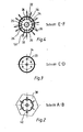
- the device contains an upper stator part 22 which has filling means for filling solids and compressed gas supply means 28 in a regular arrangement around a central axis 24. This can be seen in Fig. 4.
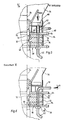
- the rotor 20 is rotatable about the central axis 24. It rests with an upper, first sealing surface 30 on a sealing surface 32 of the upper stator part 22 (FIGS. 5 and 6).
- the rotor 20 has a ring of chambers 34 which pass from the upper, first sealing surface 30 to a lower, second sealing surface 36 and which are arranged in a regular arrangement around the central axis 24 such that the chambers 34 at one point development of the rotor 20 with the filling means 26 and in another position with the compressed gas supply means 28.
- the device contains a lower stator part 38, which bears with a sealing surface 40 on the second sealing surface 36 of the rotor.
- the lower stator part 38 has a plurality of outlet channels 42 in alignment with the compressed gas supply means 28.
- the rotor 20 is driven in the manner described by drive means 44 in the form of the motor 14, the gear 16 and the chain drive 18.
- the outlet channels 42 are connected by hoses 46 with connections 48 to a combustion chamber 50 of an industrial furnace 52.
- the connections 48 are air supply connections, via which compressed air is blown into the combustion chamber 50 from a ring line 54.
- the end of the hose 46 or a tube 56 connected thereto protrudes centrally into the connection 48. The solids blown in through the hose 46 are therefore entrained with the air flow conducted into the combustion chamber 50 via the connection 48.
- venting means 58 are provided in the upper stator part 22 between the compressed gas supply means 28 and the insertion means 26 assigned to the next cycle.
- the upper stator part 22 forms an annular chamber 60 which is delimited by an upper and a lower plate 62 or 64.
- the filling means 26 contain pipe sections 66_ (FIG. 5) which extend vertically through the annular chamber 60 and. each connect an opening 68 of the upper plate 62 with an opening of the lower plate 64.
- a sealing washer 72 which forms the sealing surface 32 and has openings 74 which are aligned with the openings 70 of the lower plate 64.
- the top plate 62 forms the bottom of a hopper 76 for solids to be filled.
- the compressed gas supply means 28 each contain a separate compressed gas line 78 (FIG. 6), which is guided through the annular chamber 60 to an opening 80 in the lower plate 64 and an opening 82 in the sealing disk 72 which is flush therewith.
- the pressures in the compressed gas lines 78 are individually adjustable.
- the lower stator part 38 contains a plate 84 and a sealing disk 86 forming the sealing surface 40.
- the plate 84 and the sealing disk 86 have openings 88 and 90, which are aligned with one another and with the openings 80, 82, and are connected to the outlet channels 42.
- the speed of the rotor 20 is continuously adjustable by the drive means 44 described.
- the adjustability of the pressures of the pressurized gas on the pressurized gas lines 78 allows the different lengths of the hoses 46 to be compensated, so that the solids can be fed in the same way to all connections of the industrial furnace 52 (on the front and the back).
- the amount of solids supplied per unit of time is determined by the volumes of the chambers 34 and the speed of the rotor 20. By changing the speed of the rotor 20, the amount of solids supplied per unit of time can be changed continuously.
Landscapes
- Engineering & Computer Science (AREA)
- Chemical & Material Sciences (AREA)
- Materials Engineering (AREA)
- Organic Chemistry (AREA)
- Metallurgy (AREA)
- Mechanical Engineering (AREA)
- Manufacturing & Machinery (AREA)
- General Engineering & Computer Science (AREA)
- Combustion & Propulsion (AREA)
- Muffle Furnaces And Rotary Kilns (AREA)
- Crucibles And Fluidized-Bed Furnaces (AREA)
- Manufacture Of Iron (AREA)
- Vertical, Hearth, Or Arc Furnaces (AREA)
Abstract
Description
- Die Erfindung betrifft ein Verfahren zum Einblasen von Feststoffen in Industrieöfen mittels Druckgas. Weiterhin betrifft die Erfindung eine Vorrichtung zur Durchführung dieses Verfahrens.
- Es ist bekannt, in Industrieöfen, beispielsweise Kupolöfen, zusätzlich Kohlestaub einzublasen, um auf diese Weise den Verbrauch an teuereren Energieträgern wie Koks zu reduzieren. Das Einblasen des Kohlestaubs muß dabei im wesentlichen gleichmäßig auf allen Seiten des Kupolofens erfolgen. Anderenfalls besteht die Gefahr eines ungleichmäßigen Abbrandes der Auskleidung.
- Das Einblasen von Feststoffen in Industrieöfen kann auch in anderem Zusammenhang sinnvoll sein. Statt in Kupolöfen können Feststoffe in Hochöfen oder Schmiedeöfen eingeblasen werden. Eine andere Anwendung könnte das Einblasen von Kohlestaub in Öfen für die Müllverbrennung sein. Statt Kohlestaub oder anderen brennbaren Feststoffen können auch andere, nicht brennbare Feststoffe aus metallurgischen Gründen in einen Industrieofen eingeblasen werden, beispielsweise ein Kalzium-Silizium-Material oder Eisenschwamm.
- Der Erfindung liegt die Aufgabe zugrunde, ein Verfahren zum Einblasen von Feststoffen in Industrieöfen mittels Druckgas zu schaffen, bei welchem die Feststoffe an verschiedenen Stellen in definierten Mengen eingeblasen werden können.
- Erfindungsgemäß wird diese Aufgabe dadurch gelöst, daß
- (a) die Feststoffe in Kammern eingefüllt werden und
- (b) die Füllungen der Kammern anschließend durch Druckgas an verschiedenen Stellen in den Industrieofen eingeblasen wird.
- Auf diese Weise wird die Menge der Feststoffe jeweils in den Kammern dosiert. Es kann dann sichergestellt werden, daß beim Ausblasen der Kammern an den verschiedenen Stellen des Industrieofens jeweils gleiche Mengen an Feststoffen in den Industrieofen eingeblasen werden, so daß eine gleichmäßige Verteilung der Feststoffe gewährleistet ist.
- Eine Vorrichtung zur Durchführung dieses Verfahrens ist gekennzeichnet durch
- (a) einen oberen Statorteil, der um eine Mittelachse herum in regelmäßiger Anordnung abwechselnd
- (a1 ) Einfüllmittel zum Einfüllen von Feststoffen und
- (a2 ) Druckgaszufuhrmittel aufweist,
- (b) einen Rotor, der
- (bl) um die Mittelachse drehbar ist,
- (b2 ) mit einer ersten Dichtfläche an einer Dichtfläche des oberen Statorteils anliegt und
- (b3 ) einen Kranz von Kammern aufweist, welche von der oberen ersten Dichtfläche zu einer unteren zweiten Dichtfläche durchgehen und welche in regelmäßiger Anordnung so um die Mittelachse angeordnet sind, daß die Kammern bei einer Stellung des Rotors mit den Einfüllmitteln und bei einer anderen Stellung mit den Druckgaszufuhrmitteln fluchten,
- (c) einen unteren Statorteil, der mit einer Dichtfläche an der zweiten Dichtfläche des Rotors anliegt und eine Mehrzahl von Auslaßkanälen fluchtend mit den Druckgaszufuhrmitteln aufweist,
- (d) Mittel zum Antreiben des Rotors und
- (e) Mittel zum Verbinden der Auslaßkanäle des unteren Statorteils mit Anschlüssen an eine Brennkammer des Industrieofens.
- Die Vorrichtung beruht auf einem ähnlichen Prinzip wie bekannte Spritzmaschinen für Feuerfestmassen, z.B. nach DE-OS 20 56 836 oder DE-AS 25 56 797. Im Gegensatz zu den bekannten Spritzmaschinen werden jedoch bei der erfindungsgemäßen Vorrichtung die Feststoffe parallel auf eine Mehrzahl von Auslaßkanälen gegeben, wobei die auf jeden der Auslaßkanäle gegebene Menge an Fes-tstoff vorher durch Abmessen in einer Kammer des Rotors bestimmt ist. Es kann daher sichergestellt werden, daß auf alle Auslaßkanäle gleiche Mengen an Feststoffen gegeben werden, die an den verschiedenen Stellen in den Industrieofen eingeblasen werden.
- Ausgestaltungen der Erfindung sind Gegenstand der Unteransprüche.
- Ein Ausführungsbeispiel der Erfindung ist nachstehend unter Bezugnahme auf die zugehörigen Zeichnungen näher erläutert:
- Fig. 1 zeigt eine Seitenansicht einer Vorrichtung zum Einblasen von Feststoffen in Industrieöfen mittels Druckluft.
- Fig. 2 zeigt einen Schnitt längs der Linie A-B von Fig.l.
- Fig. 3 zeigt einen Schnitt längs der Linie C-D von Fig.l.
- Fig. 4 zeigt einen Schnitt längs der Linie E-F von Fig.l.
- Fig. 5 zeigt eine Einzelheit "X" von Fig.l im Längsschnitt und vergrößertem Maßstab.
- Fig. 6 zeigt in ähnlicher Darstellung wie Fig.5 einen gegenüber dem Längsschnitt von Fig.5 etwas winkelversetzten Längsschnitt.
- Fig. 7 zeigt schematisch die Anwendung der beschriebenen Vorrichtung bei einem Industrieofen.
- Die Vorrichtung gemäß Fig.l ist auf einem Wagen 10 gelagert, der mitttels einer Deichsel 12 bewegbar ist. Auf dem Wagen 10 ist ein Antriebsmotor 14 mit einem Getriebe 16 montiert, der über eine Kette 18 einen Rotor 20 antreibt.
- Die Vorrichtung enthält einen oberen Statorteil 22, der um eine Mittelachse 24 herum in regelmäßiger Anordnung Einfüllmittel zum Einfüllen von Feststoffen und Druckgaszufuhrmittel 28 aufweist. Das ist in Fig.4 erkennbar. Der Rotor 20 ist um die Mittelachse 24 drehbar. Er liegt mit einer oberen, ersten Dichtfläche 30 an einer Dichtfläche 32 des oberen Statorteils 22 an (Fig.5 und 6). Der Rotor 20 weist einen Kranz von Kammern 34 auf, welche von der oberen, ersten Dichtfläche 30 zu einer unteren, zweiten Dichtfläche 36 durchgehen und welche in regelmäßiger Anordnung so um die Mittelachse 24 angeordnet sind, daß die Kammern 34 bei einer Stellung des Rotors 20 mit den Einfüllmitteln 26 und bei einer anderen Stellung mit den Druckgaszufuhrmitteln 28 fluchten. Schließlich enthält die Vorrichtung einen unteren Statorteil 38, der mit einer Dichtfläche 40 an der zweiten Dichtfläche 36 des Rotors anliegt. Der untere Statorteil 38 weist eine Mehrzahl von Auslaßkanälen 42 fluchtend mit den Druckgaszufuhrmitteln 28 auf. Der Rotor 20 wird in der beschriebenen Weise durch Antriebsmittel 44 in Form des Motors 14, des Getriebes 16 und des Kettentriebs 18 angetrieben. Die Auslaßkanäle 42 sind durch Schläuche 46 mit Anschlüssen 48 an eine Brennkammer 50 eines Industrieofens 52 verbunden. Die Anschlüsse 48 sind Luftzufuhranschlüsse, über welche aus einer Ringleitung 54 Druckluft in die Brennkammer 50 eingeblasen wird. Das Ende des Schlauches 46 bzw. eines daran angeschlossenen Rohres 56 ragt zentral in den Anschluß 48 hinein. Die über den Schlauch 46 eingeblasenen Feststoffe werden daher mit dem über den Anschluß 48 in die Brennkammer 50 geleiteten Luftstrom mitgerissen.
- Wie aus Fig.4 ersichtlich ist, sind in dem oberen Statorteil 22 zwischen den Druckgaszufuhrmitteln 28 und den dem nächsten Zyklus zugeordneten Einführmitteln 26 jeweils Entlüftungsmittel 58 vorgesehen.
- Der obere Statorteil 22 bildet eine Ringkammer 60, die von einer oberen und einer unteren Platte 62 bzw. 64 begrenzt ist. Die Einfüllmittel 26 enthalten Rohrstücke 66_(Fig.5), die sich vertikal durch die Ringkammer 60 erstrecken und. jeweils einen Durchbruch 68 der oberen Platte 62 mit einem Durchbruch der unteren Platte 64 verbinden. Auf der unteren Platte sitzt eine Dichtscheibe 72, welche die Dichtfläche 32 bildet und Durchbrüche 74 aufweist, die mit den Durchbrüchen 70 der unteren Platte 64 fluchten. Die obere Platte 62 bildet den Boden eines Einfülltrichters 76 für einzufüllende Feststoffe. Die Druckgaszufuhrmittel 28 enthalten je eine gesonderte Druckgasleitung 78 (Fig.6), die durch die Ringkammer 60 hindurch zu einem Durchbruch 80 der unteren Platte 64 und einem damit fluchtenden Durchbruch 82 der Dichtscheibe 72 geführt ist.
- Die Drücke in den Druckgasleitungen 78 sind einzeln einstellbar. Der untere Statorteil 38 enthält eine Platte 84 und eine die Dichtfläche 40 bildende Dichtscheibe 86. Die Platte 84 und die Dichtscheibe 86 weisen miteinander und mit den Durchbrüchen 80,82 fluchtende Durchbrüche 88 bzw. 90 auf, die mit den Auslaßkanälen 42 in Verbindung stehen.
- Die Drehzahl des Rotors 20 ist durch die beschriebenen Antriebsmittel 44 stufenlos regelbar. Die Einstellbarkeit der Drücke des Druckgases an den Druckgasleitungen 78 gestattet einen Ausgleich der unterschiedlichen Längen der Schläuche 46, so daß die Feststoffe in gleicher Weise allen Anschlüssen des Industrieofens 52 (auf der Vorder- und der Rückseite) zugeführt werden können. Die Menge der pro Zeiteinheit zugeführten Feststoffe wird durch die Volumina der Kammern 34 und die Drehzahl des Rotors 20 bestimmt. Durch Veränderung der Drehzahl des Rotors 20 kann die pro Zeiteinheit zugeführte Menge an Feststoffen stufenlos verändert werden.
Claims (7)
Priority Applications (1)
| Application Number | Priority Date | Filing Date | Title |
|---|---|---|---|
| AT86101955T ATE46540T1 (de) | 1985-03-22 | 1986-02-15 | Verfahren und vorrichtung zum einblasen von feststoffen in industrieoefen. |
Applications Claiming Priority (2)
| Application Number | Priority Date | Filing Date | Title |
|---|---|---|---|
| DE19853510443 DE3510443A1 (de) | 1985-03-22 | 1985-03-22 | Verfahren und vorrichtung zum einblasen von feststoffen in industrieoefen |
| DE3510443 | 1985-03-22 |
Publications (3)
| Publication Number | Publication Date |
|---|---|
| EP0195250A2 true EP0195250A2 (de) | 1986-09-24 |
| EP0195250A3 EP0195250A3 (en) | 1987-10-07 |
| EP0195250B1 EP0195250B1 (de) | 1989-09-20 |
Family
ID=6266058
Family Applications (1)
| Application Number | Title | Priority Date | Filing Date |
|---|---|---|---|
| EP86101955A Expired EP0195250B1 (de) | 1985-03-22 | 1986-02-15 | Verfahren und Vorrichtung zum Einblasen von Feststoffen in Industrieöfen |
Country Status (3)
| Country | Link |
|---|---|
| EP (1) | EP0195250B1 (de) |
| AT (1) | ATE46540T1 (de) |
| DE (2) | DE3510443A1 (de) |
Cited By (1)
| Publication number | Priority date | Publication date | Assignee | Title |
|---|---|---|---|---|
| WO2016174237A1 (fr) * | 2015-04-29 | 2016-11-03 | Engie | Système de production d'énergie et procédé d'approvisionnement en produit d'un équipement de production d'énergie associé |
Families Citing this family (3)
| Publication number | Priority date | Publication date | Assignee | Title |
|---|---|---|---|---|
| DE3911982A1 (de) * | 1989-04-12 | 1990-10-25 | Schuster Walter Prof Dr | Verfahren zum beseitigen von abfaellen |
| DE4104252C2 (de) * | 1991-02-13 | 1998-07-02 | Schingnitz Manfred | Entsorgungsverfahren für schadstoffbelastete, kohlenstoffhaltige Abfallstoffe |
| DE19541673A1 (de) * | 1994-11-14 | 1996-08-29 | Krupp Ag Hoesch Krupp | Verfahren zum Herstellen von pneumatisch förderbaren und einblasfähigen Kohlenstaub-Kunststoff-Gemischen |
Family Cites Families (8)
| Publication number | Priority date | Publication date | Assignee | Title |
|---|---|---|---|---|
| GB1067191A (en) * | 1962-10-17 | 1967-05-03 | Koppers Co Inc | Improvements in or relating to injection of particulate material into furnaces |
| FR1434839A (fr) * | 1964-05-29 | 1966-04-08 | Kloeckner Werke Ag | Dispositif de distribution permettant d'introduire des additifs dans les tuyères de hauts fourneaux |
| DE2041307A1 (de) * | 1969-08-29 | 1971-03-11 | Rotary Hoes Ltd | Verteiler zum Zufuehren eines koernigen,in einem Druckgas enthaltenen Materials zu einem Behaelter |
| US4052041A (en) * | 1976-12-15 | 1977-10-04 | Vonstroh Iii Gerald F H H | Apparatus for injecting granular material into a molten metal |
| DE2800320A1 (de) * | 1977-02-25 | 1978-08-31 | Lingl Corp | Verfahren und vorrichtung zur verteilung von pulverfoermigem festen brennstoff an brennereinheiten |
| US4232854A (en) * | 1978-05-26 | 1980-11-11 | Barbakadze Dzhondo F | Method of introducing powdered reagents into molten metals and apparatus for effecting same |
| EP0036894A1 (de) * | 1980-03-19 | 1981-10-07 | Fritz Dr.-Ing. Schoppe | Kohlenstaubtank mit Einrichtung zum dosierten Austragen insbesondere kleiner Kohlenstaubmengen |
| LU84172A1 (fr) * | 1982-05-28 | 1983-11-23 | Wurth Paul Sa | Procede et dispositif de controle de la pression d'un fluide de propulsion pneumatique dans un sas a rotor alveolaire |
-
1985
- 1985-03-22 DE DE19853510443 patent/DE3510443A1/de not_active Withdrawn
-
1986
- 1986-02-15 DE DE8686101955T patent/DE3665737D1/de not_active Expired
- 1986-02-15 AT AT86101955T patent/ATE46540T1/de not_active IP Right Cessation
- 1986-02-15 EP EP86101955A patent/EP0195250B1/de not_active Expired
Cited By (2)
| Publication number | Priority date | Publication date | Assignee | Title |
|---|---|---|---|---|
| WO2016174237A1 (fr) * | 2015-04-29 | 2016-11-03 | Engie | Système de production d'énergie et procédé d'approvisionnement en produit d'un équipement de production d'énergie associé |
| FR3035706A1 (fr) * | 2015-04-29 | 2016-11-04 | Gdf Suez | Systeme de production d'energie et procede d'approvisionnement en produit d'un equipement de production d'energie associe |
Also Published As
| Publication number | Publication date |
|---|---|
| EP0195250B1 (de) | 1989-09-20 |
| EP0195250A3 (en) | 1987-10-07 |
| DE3510443A1 (de) | 1986-09-25 |
| ATE46540T1 (de) | 1989-10-15 |
| DE3665737D1 (en) | 1989-10-26 |
Similar Documents
| Publication | Publication Date | Title |
|---|---|---|
| DE3019888C2 (de) | ||
| DE2924317C2 (de) | Zweistufige Strangpreßvorrichtung für thermoplastische Formmassen, insbesondere für pulverförmige Kunststoffe | |
| DE2509400C3 (de) | Kraftstoffeinspritzmechanismus | |
| EP0195250A2 (de) | Verfahren und Vorrichtung zum Einblasen von Feststoffen in Industrieöfen | |
| DE2510963A1 (de) | Vorrichtung zum einfaerben von farblosem kunststoff-granulat | |
| DE3524011C2 (de) | ||
| DE3617008A1 (de) | Gasdetonationsanlage zum auftragen von ueberzuegen | |
| EP0082886A1 (de) | Verfahren zum Brennen von Kalkstein, Dolomit oder ähnlichem Material sowie Ringschachtofen zu dessen Durchführung | |
| DE3722314A1 (de) | Einschleusvorrichtung fuer trockenes betongemisch und aehnliche baustoffe in eine pneumatische spritzfoerderleitung sowie spritzmaschine mit einer solchen einschleusvorrichtung | |
| DE3912012A1 (de) | Trockner fuer eine asphaltfabrik | |
| DE513378C (de) | Sandschleuderformmaschine | |
| DE2617490A1 (de) | Verfahren und vorrichtung zur zufuehrung von trockenem, fliessfaehigem kohlenstaub in einen hochdruck-kohlevergasungsreaktor | |
| CH680274A5 (en) | Sand blasting device - has changeover equipment connecting nozzle hose to sand pressure vessels alternately | |
| DE1508193B1 (de) | Verfahren und Vorrichtung zur Heissreparatur von insbesondere Siemens-Martin-Ofen-Abstichen | |
| DE1940760C3 (de) | Lichtbogenofenanlage zur Stahlherstellung | |
| DE19909132A1 (de) | Vorrichtung zum Fördern von Schüttgütern | |
| EP1521816A1 (de) | Verfahren zum bef llen eines horizontalkammerkoksofens | |
| DE443057C (de) | Einrichtung zum Entleeren geschlossener Staubbehaelter | |
| DE3837263C1 (en) | Apparatus for producing mouldings from concrete | |
| DE1169474B (de) | Drehbare Begichtungseinrichtung eines fortlaufend mit ebenem Spiegel zu fuellenden Schachtes, insbesondere eines Hochofens | |
| DE3311841A1 (de) | Spritz- und foerdervorrichtung fuer trockenes material in pulver- oder granulatform fuer das bauwesen und die industrie | |
| DE967281C (de) | Pneumatisch betriebene Versatzmaschine | |
| AT399118B (de) | Vorrichtung zum befüllen von pressformen mit einer oder mehreren formöffnungen an pressformen einer presse | |
| DE3608112A1 (de) | Verfahren und vorrichtung fuer die erzeugung eines gasfoermigen haertemittels | |
| DE3839756C2 (de) |
Legal Events
| Date | Code | Title | Description |
|---|---|---|---|
| PUAI | Public reference made under article 153(3) epc to a published international application that has entered the european phase |
Free format text: ORIGINAL CODE: 0009012 |
|
| AK | Designated contracting states |
Kind code of ref document: A2 Designated state(s): AT DE FR IT NL |
|
| PUAL | Search report despatched |
Free format text: ORIGINAL CODE: 0009013 |
|
| AK | Designated contracting states |
Kind code of ref document: A3 Designated state(s): AT DE FR IT NL |
|
| 17P | Request for examination filed |
Effective date: 19880330 |
|
| 17Q | First examination report despatched |
Effective date: 19880824 |
|
| GRAA | (expected) grant |
Free format text: ORIGINAL CODE: 0009210 |
|
| AK | Designated contracting states |
Kind code of ref document: B1 Designated state(s): AT DE FR IT NL |
|
| REF | Corresponds to: |
Ref document number: 46540 Country of ref document: AT Date of ref document: 19891015 Kind code of ref document: T |
|
| REF | Corresponds to: |
Ref document number: 3665737 Country of ref document: DE Date of ref document: 19891026 |
|
| ITF | It: translation for a ep patent filed | ||
| ET | Fr: translation filed | ||
| PLBE | No opposition filed within time limit |
Free format text: ORIGINAL CODE: 0009261 |
|
| STAA | Information on the status of an ep patent application or granted ep patent |
Free format text: STATUS: NO OPPOSITION FILED WITHIN TIME LIMIT |
|
| 26N | No opposition filed | ||
| ITTA | It: last paid annual fee | ||
| PGFP | Annual fee paid to national office [announced via postgrant information from national office to epo] |
Ref country code: FR Payment date: 19980205 Year of fee payment: 13 |
|
| PGFP | Annual fee paid to national office [announced via postgrant information from national office to epo] |
Ref country code: AT Payment date: 19980213 Year of fee payment: 13 |
|
| PGFP | Annual fee paid to national office [announced via postgrant information from national office to epo] |
Ref country code: NL Payment date: 19980228 Year of fee payment: 13 |
|
| PGFP | Annual fee paid to national office [announced via postgrant information from national office to epo] |
Ref country code: DE Payment date: 19980425 Year of fee payment: 13 |
|
| PG25 | Lapsed in a contracting state [announced via postgrant information from national office to epo] |
Ref country code: AT Free format text: LAPSE BECAUSE OF NON-PAYMENT OF DUE FEES Effective date: 19990215 |
|
| PG25 | Lapsed in a contracting state [announced via postgrant information from national office to epo] |
Ref country code: NL Free format text: LAPSE BECAUSE OF NON-PAYMENT OF DUE FEES Effective date: 19990901 |
|
| PG25 | Lapsed in a contracting state [announced via postgrant information from national office to epo] |
Ref country code: FR Free format text: LAPSE BECAUSE OF NON-PAYMENT OF DUE FEES Effective date: 19991029 |
|
| PG25 | Lapsed in a contracting state [announced via postgrant information from national office to epo] |
Ref country code: DE Free format text: LAPSE BECAUSE OF NON-PAYMENT OF DUE FEES Effective date: 19991201 |
|
| REG | Reference to a national code |
Ref country code: FR Ref legal event code: ST |
|
| PG25 | Lapsed in a contracting state [announced via postgrant information from national office to epo] |
Ref country code: IT Free format text: LAPSE BECAUSE OF NON-PAYMENT OF DUE FEES;WARNING: LAPSES OF ITALIAN PATENTS WITH EFFECTIVE DATE BEFORE 2007 MAY HAVE OCCURRED AT ANY TIME BEFORE 2007. THE CORRECT EFFECTIVE DATE MAY BE DIFFERENT FROM THE ONE RECORDED. Effective date: 20050215 |