EP0195384A1 - Speiseschaltung für Lichterzeuger mit variablen Farben - Google Patents
Speiseschaltung für Lichterzeuger mit variablen Farben Download PDFInfo
- Publication number
- EP0195384A1 EP0195384A1 EP86103471A EP86103471A EP0195384A1 EP 0195384 A1 EP0195384 A1 EP 0195384A1 EP 86103471 A EP86103471 A EP 86103471A EP 86103471 A EP86103471 A EP 86103471A EP 0195384 A1 EP0195384 A1 EP 0195384A1
- Authority
- EP
- European Patent Office
- Prior art keywords
- signal
- counter
- light sources
- outputs
- output
- Prior art date
- Legal status (The legal status is an assumption and is not a legal conclusion. Google has not performed a legal analysis and makes no representation as to the accuracy of the status listed.)
- Granted
Links
Images


Classifications
-
- H—ELECTRICITY
- H05—ELECTRIC TECHNIQUES NOT OTHERWISE PROVIDED FOR
- H05B—ELECTRIC HEATING; ELECTRIC LIGHT SOURCES NOT OTHERWISE PROVIDED FOR; CIRCUIT ARRANGEMENTS FOR ELECTRIC LIGHT SOURCES, IN GENERAL
- H05B39/00—Circuit arrangements or apparatus for operating incandescent light sources
- H05B39/09—Circuit arrangements or apparatus for operating incandescent light sources in which the lamp is fed by pulses
-
- F—MECHANICAL ENGINEERING; LIGHTING; HEATING; WEAPONS; BLASTING
- F21—LIGHTING
- F21S—NON-PORTABLE LIGHTING DEVICES; SYSTEMS THEREOF; VEHICLE LIGHTING DEVICES SPECIALLY ADAPTED FOR VEHICLE EXTERIORS
- F21S10/00—Lighting devices or systems producing a varying lighting effect
- F21S10/02—Lighting devices or systems producing a varying lighting effect changing colors
-
- F—MECHANICAL ENGINEERING; LIGHTING; HEATING; WEAPONS; BLASTING
- F21—LIGHTING
- F21V—FUNCTIONAL FEATURES OR DETAILS OF LIGHTING DEVICES OR SYSTEMS THEREOF; STRUCTURAL COMBINATIONS OF LIGHTING DEVICES WITH OTHER ARTICLES, NOT OTHERWISE PROVIDED FOR
- F21V33/00—Structural combinations of lighting devices with other articles, not otherwise provided for
- F21V33/0004—Personal or domestic articles
- F21V33/0052—Audio or video equipment, e.g. televisions, telephones, cameras or computers; Remote control devices therefor
- F21V33/0056—Audio equipment, e.g. music instruments, radios or speakers
-
- Y—GENERAL TAGGING OF NEW TECHNOLOGICAL DEVELOPMENTS; GENERAL TAGGING OF CROSS-SECTIONAL TECHNOLOGIES SPANNING OVER SEVERAL SECTIONS OF THE IPC; TECHNICAL SUBJECTS COVERED BY FORMER USPC CROSS-REFERENCE ART COLLECTIONS [XRACs] AND DIGESTS
- Y10—TECHNICAL SUBJECTS COVERED BY FORMER USPC
- Y10S—TECHNICAL SUBJECTS COVERED BY FORMER USPC CROSS-REFERENCE ART COLLECTIONS [XRACs] AND DIGESTS
- Y10S362/00—Illumination
- Y10S362/806—Ornamental or decorative
- Y10S362/811—Psychedelic lighting
Definitions
- the present invention relates to a device for supplying a light emitting element equipped with at least two light sources each radiating a different fundamental color, the tint emitted by said element changing color as a function of variations in a analog electrical signal supplied by a physical phenomenon sensor, in particular a microphone.
- Document FR-A-2 186 624 proposes a set of three light sources of different colors combined with a reflector ensuring the mixing of these colors.
- a strip of paper with three tracks is used, the transparency of which varies according to the illumination to be provided at each instant by each light source. The transparency is measured by photoelectric cells so that when the strip passes, the resulting shade emitted by the reflector varies.
- Document US Pat. No. 3,564,332 describes a system very similar to that which has just been mentioned, where the color change control element is in the form of a continuously rotating disc.
- the present invention is characterized in that the device for supplying light sources comprises a converter capable of converting the analog signal supplied by a sensor, in particular a microphone, into a series of electrical pulses whose rising or falling edges follow one another at a rate which is dependent on the variations of said analog signal and a counter using the rising or falling edges of each of said pulses to provide at its output a coded signal whose state changes each time one of said rising or falling edges is applied to said counter, each of said states of said coded signal determining a predetermined state of excitation of said light sources.
- an important aim which the present invention proposes to achieve is to make the ignition of light sources depend not on the frequency or on the level of an analog signal, such as that coming from a microphone for example, but on a coded signal which changes according to the variations of this signal. Each change of state of the coded signal corresponds to a different excitation of the light sources and this according to a determined sequence which is repeated.
- Another object which the invention proposes to achieve is to implement a code converter whose role consists, for a determined sequence, in increasing the number of possible states that the coded signal can take in this sequence.
- Figure 1 shows a light emitting element equipped with three light sources referenced B (blue), G (green) and R (red).
- the color emitted by this element will change color to function of variations in an analog electrical signal supplied by a physical phenomenon sensor, here a microphone 1.
- a microphone 1 As the voltage collected across the microphone is low, it is amplified by amplifier 2 at the output of which there is a signal 8 of sufficient amplitude to attack the device according to the invention.
- This device firstly comprises a converter 3 which transforms the analog signal 8 into a series of pulses 9 whose rising sides 6 and falling 7 follow one another at a rate which is dependent on variations in the analog signal 8.
- the power supply device also comprises a counter 4 which uses the rising or falling edges (here preferably the rising edges 6) of each of said pulses 9 to provide at its output a coded signal 10 whose state changes each time it is applied at the counter 4 one of the rising or falling sides of the pulses 9.
- a coded signal 10 whose state changes each time it is applied at the counter 4 one of the rising or falling sides of the pulses 9.
- Each of the successive states occurring at the output of the counter 4 determines a determined state of excitation of the light sources.
- the state 1 0 1 of the signal 10 excites the lamps B and R while the lamp G remains off. If B and R radiate a blue and red color respectively, the tint of the light emitting element 5 will be purple.
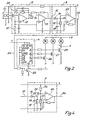
- FIG. 2 is a detailed diagram of the supply device, the principle diagram of which has been explained above and according to a first embodiment. Here we find the different elements 1, 2, 3, 4 and 5 exposed in Figure 1 and which will now be explained in detail.
- the physical phenomenon sensor 1 makes it possible to correspond to the amplitude of a physical quantity a determined shade.
- the quantity in question is an acoustic or musical signal picked up by a microphone. It could however be another quantity, for example the angle of rotation of an axis, the displacement of a control handle, a temperature, etc.
- the microphone used is preferably of the electret type with its own preamplifier.
- the electrical signals from the microphone 1 are then applied to an amplifier 2 which comprises two operational amplifiers 12 and 13 connected in cascade.
- a potentiometer 14 makes it possible to adjust the gain of amplifier 2.
- Block 2 is supplied with DC voltage, like blocks 1, 3 and 4 moreover, by a source not shown and by means of the lines marked +.
- An analog signal having the appearance of that referenced 8 in FIG. 1 is collected at the output 15 of the amplifier 2.
- the signal present on line 15 is then applied to converter 3 whose purpose is to convert said signal into a series of electrical pulses appearing on the output line 24 of said converter.
- this conversion is done as follows:
- the analog signal is rid of its negative half-wave.
- the remaining positive half-cycle is shown under reference 17 in FIG. 3a.
- the signal thus rectified is then applied to an integrator formed by the capacitor 18 and the resistor 19, which results in the formation, at point 20, of a new signal which is the envelope of the rectified analog signal as can be see at 21 in Figure 3a.
- the envelope signal 21 is applied to an operational amplifier 22 operating as a comparator.
- the signal 21 is compared in this comparator to a voltage threshold which is referenced 23 in FIG.
- the pulses of FIG. 3b are then applied to the counter 4 on its input Cl (clock) after having passed through the inverter 25.
- the counter 4 changes state each time a rising edge is applied to its input Cl while it is insensitive to the falling edge of the control pulses.
- On the outputs Q 1 , Q 2 and Q 3 of the counter there are the successive situations given by the following table which also gives the sequence of lighting of the light sources R, G, B as and when the flanks appear amounts at the Cl input of the counter:
- FIG. 3a shows that the choice value of the voltage threshold 23 is critical. If the musical level is very high, it will remain above this threshold and there will be little or no change in color. Conversely, in the case of a low musical level, the envelope signal could be confined below the threshold 23.
- an amplifier 2 could be used which would be equipped with automatic gain control (AGC). instead of the manual control provided by element 14.
- AGC automatic gain control
- FIG. 4 represents a modified converter 3, all the other blocks being similar to those discussed in connection of Figure 2.
- the converter 3 of Figure 4 includes a differentiator disposed between the integrator 18, 19 and the comparator 22.
- This differentiator includes the capacitor 33 and the two resistors 34 and 35.
- the envelope signal present at point 20 is applied to capacitor 33 of the differentiator.
- the aim of this system is first of all to bring the envelope signal to center around a zero level and then, if the value of the capacitor 33 is chosen to be low enough with respect to the resistors 34 and 35, to cause the comparator on the slope of the envelope signal.
- FIG. 5a shows the appearance of the differentiated signal such that it appears after the capacitor 33 and as it is applied to the comparator 22.
- the differentiated signal is compared to the threshold voltage 36, which produces at the output of the comparator the series of pulses which appears in FIG. 5c.
- the rising edges 6 of the signal change the state of the counter 4, which produces a sequence of tones consecutive to the various successive states taken by the outputs Q 1 Q 2 Q 3 of the counter 4.
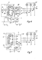
- Figure 6 is a partial diagram of the supply device according to a third embodiment.
- the outputs Q 1 , Q 2 and Q 3 of the counter 4 are connected to a NAND gate 38 and, on the other hand, the same three outputs are connected to the switches 28, 27 and 26 by through doors 39, 40 and 41 respectively.
- the output of gate 38 is connected to the LOAD input of the counter, that the input P 1 is connected to the most of the power supply while the inputs P 2 and P 3 are connected to ground.
- the purpose of this combination is to prevent the state 0 0 0 at the output of the counter.
- a signal 0 arises at the output of the said door, which has the consequence of preselecting the counter according to the state imposed on the inputs P 1 , P 2 and P 3 when the next rising edge Cl arrives.
- the preselection will be made on the value 100.
- the state 0 0 0 which is between state 1 1 1 and 1 0 0 (as we can see on the table given above) is deleted.
- the purpose of this programming is to avoid a black state in the sequence which is then reduced to 7 different states.
- door means are arranged between the outputs Q 1 , Q 2 and Q 3 of the meter and the light sources.
- the purpose of this arrangement is to prevent for a predetermined period of time the application of the coded signal to the light sources during each change of state of this signal. It has indeed been noticed that a very short pause (black pause) between the change from one color to another gives a more marked impression of this change than if the change was made without a break.
- the gates 39, 40 and 41 receive on their first inputs the signals Q 1 , Q 2 and Q 3 respectively and on their second inputs put in parallel a signal 42 which is the differentiation of the falling edge of the control pulse arriving by the line 24.
- the differentiation is carried out by the RC constituted by the capacitor 43 and the resistor 44.
- the elements 43 and 44 will be dimensioned so as to preferably obtain a pause before ignition on the order of 50 to 100 ms.
- FIG. 7 is a partial diagram of the supply device according to a fourth embodiment according to the invention.
- the code converter 45 used is of the programmable memory type generally called PROM.
- the code converter can be programmed at will and an example has just been given in the table above. We note in particular that the state 0 0 0 0 no longer needs to be deleted since it corresponds in the example given to a color, in particular white (W) result of the simultaneous excitation of the three RGB colors .
- the arrangement taken in FIG. 6 to prevent for a short period of time the application of the coded signal to the RGB light sources is also implemented in the embodiment of FIG. 7.
- the way of performing this function is however simplified by the fact that the PROM 45 converter has a single CE input. After having been differentiated by the capacitor 47 and the resistor 48, then reversed by the gate 49, the falling edge of the pulses present on the line 24 controls the input CE of the memory 45.
- the RGB light sources shown in the various figures may be of the incandescent type, each having a different colored bulb.
- the supply of these lamps is made by a DC voltage source of value + U if the switches 26, 27 and 28 are simple transistors. If this voltage were to be an alternative source, a diac-triac system which is also well known in the state of the art will be used as the semiconductor switch.
- These light sources could also be fluorescent tubes, the internal wall of each of them being covered with a different phosphor.
- the strike voltage of the tubes is repeated at the frequency of the supply network, said strike voltage being followed by a continuous arc holding voltage.
Landscapes
- Engineering & Computer Science (AREA)
- Multimedia (AREA)
- General Engineering & Computer Science (AREA)
- Circuit Arrangement For Electric Light Sources In General (AREA)
- Illuminated Signs And Luminous Advertising (AREA)
- Electrophonic Musical Instruments (AREA)
- Auxiliary Devices For Music (AREA)
Applications Claiming Priority (2)
| Application Number | Priority Date | Filing Date | Title |
|---|---|---|---|
| FR8504085A FR2579056B1 (fr) | 1985-03-18 | 1985-03-18 | Dispositif d'alimentation d'un element emetteur de lumiere a couleurs changeantes |
| FR8504085 | 1985-03-18 |
Publications (2)
| Publication Number | Publication Date |
|---|---|
| EP0195384A1 true EP0195384A1 (de) | 1986-09-24 |
| EP0195384B1 EP0195384B1 (de) | 1988-11-09 |
Family
ID=9317366
Family Applications (1)
| Application Number | Title | Priority Date | Filing Date |
|---|---|---|---|
| EP86103471A Expired EP0195384B1 (de) | 1985-03-18 | 1986-03-14 | Speiseschaltung für Lichterzeuger mit variablen Farben |
Country Status (8)
| Country | Link |
|---|---|
| US (1) | US4668895A (de) |
| EP (1) | EP0195384B1 (de) |
| JP (1) | JPS61218093A (de) |
| AU (1) | AU581587B2 (de) |
| CA (1) | CA1248460A (de) |
| DE (1) | DE3661155D1 (de) |
| FR (1) | FR2579056B1 (de) |
| SG (1) | SG90391G (de) |
Cited By (1)
| Publication number | Priority date | Publication date | Assignee | Title |
|---|---|---|---|---|
| ITMI20110051A1 (it) * | 2011-01-20 | 2012-07-21 | Orlando Coruzzi | Struttura decorativa composita, particolarmente per alberi di natale e simili applicazioni. |
Families Citing this family (93)
| Publication number | Priority date | Publication date | Assignee | Title |
|---|---|---|---|---|
| US4962687A (en) * | 1988-09-06 | 1990-10-16 | Belliveau Richard S | Variable color lighting system |
| US4980971A (en) * | 1989-12-14 | 1991-01-01 | At&T Bell Laboratories | Method and apparatus for chip placement |
| US5749646A (en) * | 1992-01-17 | 1998-05-12 | Brittell; Gerald A. | Special effect lamps |
| US5414325A (en) * | 1994-04-13 | 1995-05-09 | General Electric Company | Gas discharge lamp ballast circuit with automatically calibrated light feedback control |
| US6270229B1 (en) * | 1996-12-24 | 2001-08-07 | Tseng-Lu Chien | Audio device including an illumination arrangement |
| US6967448B2 (en) | 1997-08-26 | 2005-11-22 | Color Kinetics, Incorporated | Methods and apparatus for controlling illumination |
| US7187141B2 (en) * | 1997-08-26 | 2007-03-06 | Color Kinetics Incorporated | Methods and apparatus for illumination of liquids |
| US6777891B2 (en) * | 1997-08-26 | 2004-08-17 | Color Kinetics, Incorporated | Methods and apparatus for controlling devices in a networked lighting system |
| US6608453B2 (en) | 1997-08-26 | 2003-08-19 | Color Kinetics Incorporated | Methods and apparatus for controlling devices in a networked lighting system |
| US6897624B2 (en) * | 1997-08-26 | 2005-05-24 | Color Kinetics, Incorporated | Packaged information systems |
| US6720745B2 (en) | 1997-08-26 | 2004-04-13 | Color Kinetics, Incorporated | Data delivery track |
| US7352339B2 (en) | 1997-08-26 | 2008-04-01 | Philips Solid-State Lighting Solutions | Diffuse illumination systems and methods |
| US20040052076A1 (en) | 1997-08-26 | 2004-03-18 | Mueller George G. | Controlled lighting methods and apparatus |
| US20030133292A1 (en) | 1999-11-18 | 2003-07-17 | Mueller George G. | Methods and apparatus for generating and modulating white light illumination conditions |
| US7186003B2 (en) | 1997-08-26 | 2007-03-06 | Color Kinetics Incorporated | Light-emitting diode based products |
| US7764026B2 (en) * | 1997-12-17 | 2010-07-27 | Philips Solid-State Lighting Solutions, Inc. | Systems and methods for digital entertainment |
| US6717376B2 (en) | 1997-08-26 | 2004-04-06 | Color Kinetics, Incorporated | Automotive information systems |
| US6211626B1 (en) | 1997-08-26 | 2001-04-03 | Color Kinetics, Incorporated | Illumination components |
| US7242152B2 (en) | 1997-08-26 | 2007-07-10 | Color Kinetics Incorporated | Systems and methods of controlling light systems |
| US6888322B2 (en) * | 1997-08-26 | 2005-05-03 | Color Kinetics Incorporated | Systems and methods for color changing device and enclosure |
| US6528954B1 (en) | 1997-08-26 | 2003-03-04 | Color Kinetics Incorporated | Smart light bulb |
| US6774584B2 (en) | 1997-08-26 | 2004-08-10 | Color Kinetics, Incorporated | Methods and apparatus for sensor responsive illumination of liquids |
| US6781329B2 (en) | 1997-08-26 | 2004-08-24 | Color Kinetics Incorporated | Methods and apparatus for illumination of liquids |
| US6548967B1 (en) * | 1997-08-26 | 2003-04-15 | Color Kinetics, Inc. | Universal lighting network methods and systems |
| US7482764B2 (en) * | 1997-08-26 | 2009-01-27 | Philips Solid-State Lighting Solutions, Inc. | Light sources for illumination of liquids |
| US6869204B2 (en) | 1997-08-26 | 2005-03-22 | Color Kinetics Incorporated | Light fixtures for illumination of liquids |
| US7385359B2 (en) | 1997-08-26 | 2008-06-10 | Philips Solid-State Lighting Solutions, Inc. | Information systems |
| US6975079B2 (en) * | 1997-08-26 | 2005-12-13 | Color Kinetics Incorporated | Systems and methods for controlling illumination sources |
| US6936978B2 (en) | 1997-08-26 | 2005-08-30 | Color Kinetics Incorporated | Methods and apparatus for remotely controlled illumination of liquids |
| US6965205B2 (en) * | 1997-08-26 | 2005-11-15 | Color Kinetics Incorporated | Light emitting diode based products |
| US7427840B2 (en) * | 1997-08-26 | 2008-09-23 | Philips Solid-State Lighting Solutions, Inc. | Methods and apparatus for controlling illumination |
| US6806659B1 (en) | 1997-08-26 | 2004-10-19 | Color Kinetics, Incorporated | Multicolored LED lighting method and apparatus |
| US7064498B2 (en) * | 1997-08-26 | 2006-06-20 | Color Kinetics Incorporated | Light-emitting diode based products |
| US6624597B2 (en) | 1997-08-26 | 2003-09-23 | Color Kinetics, Inc. | Systems and methods for providing illumination in machine vision systems |
| US7038398B1 (en) * | 1997-08-26 | 2006-05-02 | Color Kinetics, Incorporated | Kinetic illumination system and methods |
| US7231060B2 (en) * | 1997-08-26 | 2007-06-12 | Color Kinetics Incorporated | Systems and methods of generating control signals |
| US7598686B2 (en) | 1997-12-17 | 2009-10-06 | Philips Solid-State Lighting Solutions, Inc. | Organic light emitting diode methods and apparatus |
| US7049761B2 (en) | 2000-02-11 | 2006-05-23 | Altair Engineering, Inc. | Light tube and power supply circuit |
| PT1422975E (pt) | 2000-04-24 | 2010-07-09 | Philips Solid State Lighting | Produto base de leds |
| US7642730B2 (en) * | 2000-04-24 | 2010-01-05 | Philips Solid-State Lighting Solutions, Inc. | Methods and apparatus for conveying information via color of light |
| US7202613B2 (en) | 2001-05-30 | 2007-04-10 | Color Kinetics Incorporated | Controlled lighting methods and apparatus |
| AU2001277185A1 (en) * | 2000-07-27 | 2002-02-13 | Color Kinetics Incorporated | Lighting control using speech recognition |
| US7042172B2 (en) * | 2000-09-01 | 2006-05-09 | Color Kinetics Incorporated | Systems and methods for providing illumination in machine vision systems |
| US7303300B2 (en) * | 2000-09-27 | 2007-12-04 | Color Kinetics Incorporated | Methods and systems for illuminating household products |
| US7038399B2 (en) | 2001-03-13 | 2006-05-02 | Color Kinetics Incorporated | Methods and apparatus for providing power to lighting devices |
| US6801003B2 (en) | 2001-03-13 | 2004-10-05 | Color Kinetics, Incorporated | Systems and methods for synchronizing lighting effects |
| US7598684B2 (en) | 2001-05-30 | 2009-10-06 | Philips Solid-State Lighting Solutions, Inc. | Methods and apparatus for controlling devices in a networked lighting system |
| US7358679B2 (en) * | 2002-05-09 | 2008-04-15 | Philips Solid-State Lighting Solutions, Inc. | Dimmable LED-based MR16 lighting apparatus and methods |
| US7300192B2 (en) * | 2002-10-03 | 2007-11-27 | Color Kinetics Incorporated | Methods and apparatus for illuminating environments |
| US7178941B2 (en) * | 2003-05-05 | 2007-02-20 | Color Kinetics Incorporated | Lighting methods and systems |
| US7827726B2 (en) * | 2005-04-26 | 2010-11-09 | Tactical Devices, Inc. | Target illumination and sighting device with integrated non-lethal weaponry |
| US10321528B2 (en) | 2007-10-26 | 2019-06-11 | Philips Lighting Holding B.V. | Targeted content delivery using outdoor lighting networks (OLNs) |
| US8118447B2 (en) * | 2007-12-20 | 2012-02-21 | Altair Engineering, Inc. | LED lighting apparatus with swivel connection |
| US7712918B2 (en) * | 2007-12-21 | 2010-05-11 | Altair Engineering , Inc. | Light distribution using a light emitting diode assembly |
| US8360599B2 (en) | 2008-05-23 | 2013-01-29 | Ilumisys, Inc. | Electric shock resistant L.E.D. based light |
| US20100220469A1 (en) * | 2008-05-23 | 2010-09-02 | Altair Engineering, Inc. | D-shaped cross section l.e.d. based light |
| US7976196B2 (en) * | 2008-07-09 | 2011-07-12 | Altair Engineering, Inc. | Method of forming LED-based light and resulting LED-based light |
| US7946729B2 (en) * | 2008-07-31 | 2011-05-24 | Altair Engineering, Inc. | Fluorescent tube replacement having longitudinally oriented LEDs |
| US8674626B2 (en) * | 2008-09-02 | 2014-03-18 | Ilumisys, Inc. | LED lamp failure alerting system |
| US8256924B2 (en) * | 2008-09-15 | 2012-09-04 | Ilumisys, Inc. | LED-based light having rapidly oscillating LEDs |
| US8901823B2 (en) | 2008-10-24 | 2014-12-02 | Ilumisys, Inc. | Light and light sensor |
| US8444292B2 (en) * | 2008-10-24 | 2013-05-21 | Ilumisys, Inc. | End cap substitute for LED-based tube replacement light |
| US8653984B2 (en) | 2008-10-24 | 2014-02-18 | Ilumisys, Inc. | Integration of LED lighting control with emergency notification systems |
| US7938562B2 (en) | 2008-10-24 | 2011-05-10 | Altair Engineering, Inc. | Lighting including integral communication apparatus |
| US8324817B2 (en) | 2008-10-24 | 2012-12-04 | Ilumisys, Inc. | Light and light sensor |
| US8214084B2 (en) | 2008-10-24 | 2012-07-03 | Ilumisys, Inc. | Integration of LED lighting with building controls |
| US8506412B2 (en) * | 2008-11-12 | 2013-08-13 | Igt | Methods and systems for wireless communication within a gaming machine |
| US8556452B2 (en) * | 2009-01-15 | 2013-10-15 | Ilumisys, Inc. | LED lens |
| US8362710B2 (en) * | 2009-01-21 | 2013-01-29 | Ilumisys, Inc. | Direct AC-to-DC converter for passive component minimization and universal operation of LED arrays |
| US8664880B2 (en) * | 2009-01-21 | 2014-03-04 | Ilumisys, Inc. | Ballast/line detection circuit for fluorescent replacement lamps |
| US8330381B2 (en) | 2009-05-14 | 2012-12-11 | Ilumisys, Inc. | Electronic circuit for DC conversion of fluorescent lighting ballast |
| US8299695B2 (en) | 2009-06-02 | 2012-10-30 | Ilumisys, Inc. | Screw-in LED bulb comprising a base having outwardly projecting nodes |
| EP2446715A4 (de) * | 2009-06-23 | 2013-09-11 | Ilumisys Inc | Beleuchtungsvorrichtung mit leds und schaltstromsteuerungssystem |
| US20100321921A1 (en) * | 2009-06-23 | 2010-12-23 | Altair Engineering, Inc. | Led lamp with a wavelength converting layer |
| CN101737700B (zh) * | 2009-12-28 | 2012-03-21 | 江苏施诺照明有限公司 | 带声控音乐彩灯的变色灯 |
| EP2553320A4 (de) | 2010-03-26 | 2014-06-18 | Ilumisys Inc | Led-licht mit thermoelektrischem generator |
| US9057493B2 (en) * | 2010-03-26 | 2015-06-16 | Ilumisys, Inc. | LED light tube with dual sided light distribution |
| EP2553332B1 (de) | 2010-03-26 | 2016-03-23 | iLumisys, Inc. | Umgestülpte led-glühlampe |
| US8454193B2 (en) | 2010-07-08 | 2013-06-04 | Ilumisys, Inc. | Independent modules for LED fluorescent light tube replacement |
| US8596813B2 (en) | 2010-07-12 | 2013-12-03 | Ilumisys, Inc. | Circuit board mount for LED light tube |
| EP2633227B1 (de) | 2010-10-29 | 2018-08-29 | iLumisys, Inc. | Mechanismen zur minimierung des risikos von elektroschocks während der installation einer lichtröhre |
| US8870415B2 (en) | 2010-12-09 | 2014-10-28 | Ilumisys, Inc. | LED fluorescent tube replacement light with reduced shock hazard |
| US9072171B2 (en) | 2011-08-24 | 2015-06-30 | Ilumisys, Inc. | Circuit board mount for LED light |
| US9184518B2 (en) | 2012-03-02 | 2015-11-10 | Ilumisys, Inc. | Electrical connector header for an LED-based light |
| WO2014008463A1 (en) | 2012-07-06 | 2014-01-09 | Ilumisys, Inc. | Power supply assembly for led-based light tube |
| US9271367B2 (en) | 2012-07-09 | 2016-02-23 | Ilumisys, Inc. | System and method for controlling operation of an LED-based light |
| US9285084B2 (en) | 2013-03-14 | 2016-03-15 | Ilumisys, Inc. | Diffusers for LED-based lights |
| US9267650B2 (en) | 2013-10-09 | 2016-02-23 | Ilumisys, Inc. | Lens for an LED-based light |
| US9574717B2 (en) | 2014-01-22 | 2017-02-21 | Ilumisys, Inc. | LED-based light with addressed LEDs |
| US9510400B2 (en) | 2014-05-13 | 2016-11-29 | Ilumisys, Inc. | User input systems for an LED-based light |
| US10161568B2 (en) | 2015-06-01 | 2018-12-25 | Ilumisys, Inc. | LED-based light with canted outer walls |
| CN105319990B (zh) * | 2015-11-19 | 2018-03-30 | 北京工业大学 | 一种音频信号控制输出光信号的方法 |
| CN215863235U (zh) * | 2021-08-16 | 2022-02-18 | 广州市五光十色舞台设备有限公司 | Led面光源以及音响 |
Citations (2)
| Publication number | Priority date | Publication date | Assignee | Title |
|---|---|---|---|---|
| FR1574966A (de) * | 1968-07-05 | 1969-07-18 | ||
| US4376404A (en) * | 1980-10-23 | 1983-03-15 | Agricultural Aviation Engineering Co. | Apparatus for translating sound into a visual display |
Family Cites Families (7)
| Publication number | Priority date | Publication date | Assignee | Title |
|---|---|---|---|---|
| US3222574A (en) * | 1963-11-22 | 1965-12-07 | Silvestri Art Mfg Co | Multichannel illumination system for controlling the intensity of illumination in each channel in response to selected frequency band of an input control signal |
| US3564332A (en) * | 1968-06-24 | 1971-02-16 | Kenneth L Blakeslee | Photoelectrically controlled continuously variable color illuminator |
| FR2186624B1 (de) * | 1972-05-05 | 1974-09-27 | Dutertre Ladure Daniel | |
| US3805049A (en) * | 1972-05-22 | 1974-04-16 | B Frank | Color pattern generator |
| US3789211A (en) * | 1972-07-14 | 1974-01-29 | Marvin Glass & Associates | Decorative lighting system |
| JPS532461U (de) * | 1976-06-25 | 1978-01-11 | ||
| US4358754A (en) * | 1981-05-26 | 1982-11-09 | Visual Marketing, Inc. | Sound-actuated advertising light display |
-
1985
- 1985-03-18 FR FR8504085A patent/FR2579056B1/fr not_active Expired
-
1986
- 1986-03-14 DE DE8686103471T patent/DE3661155D1/de not_active Expired
- 1986-03-14 EP EP86103471A patent/EP0195384B1/de not_active Expired
- 1986-03-17 US US06/840,258 patent/US4668895A/en not_active Expired - Fee Related
- 1986-03-17 CA CA000504270A patent/CA1248460A/en not_active Expired
- 1986-03-17 AU AU54856/86A patent/AU581587B2/en not_active Ceased
- 1986-03-18 JP JP61058422A patent/JPS61218093A/ja active Granted
-
1991
- 1991-10-25 SG SG903/91A patent/SG90391G/en unknown
Patent Citations (2)
| Publication number | Priority date | Publication date | Assignee | Title |
|---|---|---|---|---|
| FR1574966A (de) * | 1968-07-05 | 1969-07-18 | ||
| US4376404A (en) * | 1980-10-23 | 1983-03-15 | Agricultural Aviation Engineering Co. | Apparatus for translating sound into a visual display |
Cited By (1)
| Publication number | Priority date | Publication date | Assignee | Title |
|---|---|---|---|---|
| ITMI20110051A1 (it) * | 2011-01-20 | 2012-07-21 | Orlando Coruzzi | Struttura decorativa composita, particolarmente per alberi di natale e simili applicazioni. |
Also Published As
| Publication number | Publication date |
|---|---|
| CA1248460A (en) | 1989-01-10 |
| FR2579056B1 (fr) | 1987-04-10 |
| FR2579056A1 (fr) | 1986-09-19 |
| EP0195384B1 (de) | 1988-11-09 |
| JPS61218093A (ja) | 1986-09-27 |
| US4668895A (en) | 1987-05-26 |
| SG90391G (en) | 1991-11-22 |
| AU581587B2 (en) | 1989-02-23 |
| JPH0546678B2 (de) | 1993-07-14 |
| DE3661155D1 (en) | 1988-12-15 |
| AU5485686A (en) | 1986-09-25 |
Similar Documents
| Publication | Publication Date | Title |
|---|---|---|
| EP0195384B1 (de) | Speiseschaltung für Lichterzeuger mit variablen Farben | |
| EP0109671B1 (de) | Licht emittierendes Element | |
| FR2466046A1 (fr) | Dispositif de commande de luminosite pour un affichage lumineux de l'indication d'un appareil de mesure electronique | |
| EP0349415A1 (de) | Verfahren und Einrichtung zur Steuerung eines Matrixbildschirmes, der Grauwerte anzeigt | |
| FR2507851A1 (fr) | Circuit pour l'emission de lumieres de couleurs differentes | |
| FR2703453A1 (fr) | Codeur de valeur absolue et procédé de correction de sortie d'un codeur de valeur absolue. | |
| FR2740647A1 (fr) | Projecteur pour vehicule | |
| FR2718585A1 (fr) | Modulateur avec codage amélioré. | |
| EP0586322A1 (de) | Einrichtung zum Ermitteln und Anzeigen von defekten Lampen in einer Beleuchtungsanlage | |
| EP0082031A1 (de) | Schaltung zur Helligkeitssteuerung einer mit Gleichstrom gespeicherten Fluoreszenzlampe | |
| EP0011534B1 (de) | Verfahren und Vorrichtung zur Verarbeitung von analogischen, insbesondere pseudoperiodischen Signalen | |
| EP0010010B1 (de) | Anlage mit Schwelle zum Unterscheiden zwischen Weiss und Schwarz auf einem Dokument und solch eine Vorrichtung enthaltender Fernkopiersender | |
| EP0375038A1 (de) | Videobildwiedergabevorrichtung mit einer Kontrastregeleinheit und Verfahren zur Kontrasteinstellung einer solchen Wiedergabevorrichtung | |
| FR2643180A1 (fr) | Dispositif d'affichage monochrome a memoire du type photoconducteur-electroluminescent | |
| FR2512294A1 (fr) | Recepteur comportant un dispositif d'affichage de frequence | |
| FR2678711A1 (fr) | Dispositif d'eclairage d'ambiance a couleur et intensite reglables. | |
| FR2491696A1 (fr) | Circuit a caracteristique de transfert commandable par voie electronique | |
| EP0638993B1 (de) | Detektorverstärker für Überwachungssystem | |
| FR2584520A1 (fr) | Dispositif d'affichage comportant un reseau matriciel de sources lumineuses | |
| FR2529685A1 (fr) | Dispositif de balayage photoelectrique bistable | |
| EP0773692B1 (de) | Komprimierender Videoverstärker | |
| FR2551300A1 (fr) | Dispositif de reglage de lampes a decharge de gaz, utilisant des entrees a contact de commutation | |
| FR2498795A1 (fr) | Dispositif pour detecter les parties vides, sans enregistrement sur un disque | |
| JP2607473B2 (ja) | カラー画像信号二値化回路 | |
| FR2821520A1 (fr) | Dispositif de commande d'eclairage de diodes electroluminescentes |
Legal Events
| Date | Code | Title | Description |
|---|---|---|---|
| PUAI | Public reference made under article 153(3) epc to a published international application that has entered the european phase |
Free format text: ORIGINAL CODE: 0009012 |
|
| AK | Designated contracting states |
Kind code of ref document: A1 Designated state(s): CH DE GB IT LI |
|
| 17P | Request for examination filed |
Effective date: 19861008 |
|
| 17Q | First examination report despatched |
Effective date: 19871127 |
|
| GRAA | (expected) grant |
Free format text: ORIGINAL CODE: 0009210 |
|
| AK | Designated contracting states |
Kind code of ref document: B1 Designated state(s): CH DE GB IT LI |
|
| ITF | It: translation for a ep patent filed | ||
| REF | Corresponds to: |
Ref document number: 3661155 Country of ref document: DE Date of ref document: 19881215 |
|
| GBT | Gb: translation of ep patent filed (gb section 77(6)(a)/1977) | ||
| PLBE | No opposition filed within time limit |
Free format text: ORIGINAL CODE: 0009261 |
|
| 26N | No opposition filed | ||
| ITTA | It: last paid annual fee | ||
| PGFP | Annual fee paid to national office [announced via postgrant information from national office to epo] |
Ref country code: GB Payment date: 19940217 Year of fee payment: 9 |
|
| PGFP | Annual fee paid to national office [announced via postgrant information from national office to epo] |
Ref country code: DE Payment date: 19940315 Year of fee payment: 9 |
|
| PGFP | Annual fee paid to national office [announced via postgrant information from national office to epo] |
Ref country code: CH Payment date: 19940316 Year of fee payment: 9 |
|
| PG25 | Lapsed in a contracting state [announced via postgrant information from national office to epo] |
Ref country code: GB Effective date: 19950314 |
|
| PG25 | Lapsed in a contracting state [announced via postgrant information from national office to epo] |
Ref country code: LI Effective date: 19950331 Ref country code: CH Effective date: 19950331 |
|
| GBPC | Gb: european patent ceased through non-payment of renewal fee |
Effective date: 19950314 |
|
| REG | Reference to a national code |
Ref country code: CH Ref legal event code: PL |
|
| PG25 | Lapsed in a contracting state [announced via postgrant information from national office to epo] |
Ref country code: DE Effective date: 19951201 |
|
| PG25 | Lapsed in a contracting state [announced via postgrant information from national office to epo] |
Ref country code: IT Free format text: LAPSE BECAUSE OF NON-PAYMENT OF DUE FEES;WARNING: LAPSES OF ITALIAN PATENTS WITH EFFECTIVE DATE BEFORE 2007 MAY HAVE OCCURRED AT ANY TIME BEFORE 2007. THE CORRECT EFFECTIVE DATE MAY BE DIFFERENT FROM THE ONE RECORDED. Effective date: 20050314 |