EP0195439A2 - Rückstauverschluss - Google Patents
Rückstauverschluss Download PDFInfo
- Publication number
- EP0195439A2 EP0195439A2 EP86103730A EP86103730A EP0195439A2 EP 0195439 A2 EP0195439 A2 EP 0195439A2 EP 86103730 A EP86103730 A EP 86103730A EP 86103730 A EP86103730 A EP 86103730A EP 0195439 A2 EP0195439 A2 EP 0195439A2
- Authority
- EP
- European Patent Office
- Prior art keywords
- seat
- backflow
- hollow body
- stop according
- edge
- Prior art date
- Legal status (The legal status is an assumption and is not a legal conclusion. Google has not performed a legal analysis and makes no representation as to the accuracy of the status listed.)
- Granted
Links
Images


Classifications
-
- E—FIXED CONSTRUCTIONS
- E03—WATER SUPPLY; SEWERAGE
- E03F—SEWERS; CESSPOOLS
- E03F7/00—Other installations or implements for operating sewer systems, e.g. for preventing or indicating stoppage; Emptying cesspools
- E03F7/02—Shut-off devices
- E03F7/04—Valves for preventing return flow
Definitions
- the invention relates to a backflow valve of the type specified in the preamble of claim 1.
- the closure part is a backflow flap, which is lifted from the flow pressure by the sealing seat and, in the case of a backflow, is placed against the seat by the back pressure to shut off the backflow.
- the backflow flap is often connected to a positive drive, with which it can be fixed with pressure when there is a backflow in the closed position, so that the backflow can in no case propagate beyond the backflow trap.
- the sealing element is usually a rubber ring that is pressed onto a sealing surface of the seat.
- the invention has for its object to provide a backflow trap of the type mentioned, in which the required sealing function is ensured in the closed position even when semi-hard, hard or textile impurities are fixed or clamped in the backflow trap between the seat and the closure member.
- the circumferential wall made of soft rubber or plastic is sufficiently surface-elastic so that it yields to a degree that is fixed or trapped in the backflow trap so that the closure part nevertheless comes properly into its closed position and that a perfect seal also in the area of the trapped contaminants is achieved. It is important that the deformability of the wall goes so far that the closure part can assume its closed position regardless of the position and the size of the contamination defined in the backflow stop, the wall deforming accordingly.
- the embodiment according to claim 2 is expedient because with a conical seat surface a large sealing area between the hollow body and the seat is achieved, in which a good sealing effect on the one hand and due to the cone angle of the seat an easy releasability of the hollow body when opening the closure part are achieved on the other .
- claim 3 is also expedient, because with these shapes the sealing action is particularly good and because the hollow body can first be inserted into the seat practically without counterforce, because in the undeformed state of the hollow body there is a circumferential gap between the seat and the wall, which is only removed when the wall is deformed and sealed.
- claim 4 is also important, because by applying the top of the hollow body to this shoulder, the wall of the hollow body is deformed for sealing contact with the seat when the closure part is pressed accordingly firmly into its closed position. However, if the contact pressure for the closure part decreases, the elasticity of the wall initially causes a reversion of the hollow body, in which the wall detaches from the seat surface, before the closure part can then be opened easily. In practice, a hardness of 40 to 60 Shore for the wall has proven particularly effective.
- the stiffening plate ensures that the deformation of the hollow body mainly occurs in the area of the outer circumferential wall, where it is used to achieve a perfect sealing function.
- FIG. 7 Another alternative embodiment is set out in claim 7.
- the wall can deform when the hollow body is pressed when the closure part is closed until it is properly sealed and can swallow unevenness without impairing the sealing functions.
- the hollow body is closed and relatively stable in shape. Pressure against the top of the hollow body causes the wall to bulge to reinforce the sealing effect.
- the hollow body could also have a toroidal shape and be fixed to the base body, where it is expediently mounted like on a rim. The outer circumference of the toroidal hollow body would then form the elastic peripheral wall, which is used to achieve the required sealing seat and is deformed for sealing.
- the hollow body could also be glued or screwed to the base body, with a firm air cushion remaining.
- the feature of claim 8 is also important, because not only an additional seal can be achieved with the shoulder, but also the deformation for the wall is derived by the contact pressure of the closure part.
- a further improvement of the sealing effect is achieved with the features of claim 9, because the soft sealing ring on the conical seat also has the property of being semi-rigid or hard swallowing impurities while maintaining the sealing effect.
- the sealing effect can be further improved if the features of claim 10 are given. With the additional rubber or plastic pads, additional sealing surfaces are created, on which the closure part comes to rest in the correct closed position.
- closure part is a backflow flap of a cleaning pipe, which is pivotally suspended about an axis above the seat and is connected to an overhead pivot drive at least for the compulsory closing of the backflow closure
- the backflow flap forming the closure part already has the features that are required for a forced actuation to open or close the backflow trap, in particular when closing a gradually increasing pressure is exerted on the backflow flap, by which the wall is deformed to such an extent that it is also under Intermediate layer of rigid contamination provides a perfect seal.
- the roller sitting on the pin significantly reduces the frictional forces at the high closing forces for the backflow valve.
- claim 12 is also advantageous because it makes it easy to assemble the cleaning pipe or to retrofit a cleaning pipe previously used for faecal-free sewage for sewage containing sewage by simply replacing the insert. If the insert cannot be replaced on its own, it is also sufficient to replace only the backflow flap with the special hollow body in order to improve the sealing function even with sewage contaminated with faeces.
- a cleaning pipe (1) can be seen, the wall (42) of which has a cleaning opening (43) which is closed by a hood-shaped cover (2).
- an insert part (3) filling the pipe diameter (44) is inserted, which has a conical seat (4), which is part of a backflow stop (5).
- the insert (3) is inserted sealed with a seal (6) and is held in place by the cover (2) in this embodiment. If necessary. the insert (3) has a pointed end with which it reaches into the inlet pipe socket.
- the seat (4) could also be integrally formed on the pipe wall in the inlet area of the inlet pipe socket in the cleaning opening area.
- a conical extension (7) is provided, which embosses on the inside a sealing ring (8) made of a soft rubber or plastic with a Shore hardness between 40 and 60.
- the sealing ring (8) forms a conical seat (8a), which is adjoined by an inwardly projecting shoulder (9).
- the shoulder (9) faces away from the front end of the extension (7), which is covered by an overlapping retaining ring (20) which holds the sealing ring (8).
- this retaining ring (10) the sealing ring (8) could be fixed with an undercut (46).
- the top of the cleaning opening (43) is on part (3) or on the opening wall (45) a pivot bearing (11) for a pivot shaft (12) of a closure part designed as a backflow valve (13) is provided, the pivot shaft (12) being designed as a pin and expediently in the pivot bearing (11) is locked so that it can be rotated, but cannot be easily lifted out.
- the closure part (13) has a flap-like base body (14) on which a frustoconical hollow body (15) is fixed in a sealed manner.
- the hollow body (15) has a base edge (16) projecting inwards in this embodiment, an adjoining free wall (17) and a flat upper side (18) in which a stiffening plate (19) is embedded.
- the edge of the hollow body (15) is designated (28). It borders on the wall (17).
- the base edge (16) is sealed to the base body (14) by a retaining ring (20) with fastening screws (21).
- the backflow flap is thus an air-cushioned closure part that presses absolutely tightly onto the seat when closed, even if there is garbage or bulky objects such as short branches in between.
- a hook (22) is formed on the back of the base body (14) and carries a curved guide track (23) with an end cam (24).
- a cross pin (25) can be moved along the guideway (23), which sits at the end of a lever (26) which can be rotated with a shaft (27) in the cover (2) in order to remove the closure part (13) from the position shown in Fig 1, in which the hollow body (15) enters the seat (4), the edge (28) of the hollow body (15) abutting the shoulder (9) , whereby when the lever (26) is finally pivoted counterclockwise, the wall (17) is deformed in the direction of the arrow (29) until it fits snugly against the ring (8).
- the base edge (16) of the hollow body (15) could also be turned outwards (at 30) around the edge of the base body (14).
- a special sealing ring could also be arranged there, which in the closed position rests against the shoulder between the ring (8) and the retaining ring (10) and provides an additional seal.
- the hollow body (15) is designed as a rubber or plastic molded part with a tire-shaped shape, the frustoconical shape of which is achieved by an asymmetrical cross section.
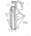
- One of the tire flanks (39) is secured in a sealed manner with a tire bead (40) by means of a plate (41) on a circumferential shoulder (33) of the base body (14).
- the other Flank (34) is clamped between two pressure plates (36 and 46), which are drawn together with screws (38), in the region of their outward-pointing bead (35).
- the outer plate (36) only has such a radial extension that it defines the upper side (18 ') of the hollow body (15'), but leaves the outer edge (28) with which the hollow body (15 ') can be placed against the shoulder (9) of the seat (4) in order to arch the elastic wall (17) outwards.
- the closure part (13 ') is here again a backflow flap for the backflow closure according to FIGS. 1 and 2.
- a toroidal or tubular hollow body such as a tire could be fixed on the base body (14 or 14) be, which forms with its outer circumference the elastically deformable wall for the sealing function.
Landscapes
- Health & Medical Sciences (AREA)
- Life Sciences & Earth Sciences (AREA)
- Engineering & Computer Science (AREA)
- Hydrology & Water Resources (AREA)
- Public Health (AREA)
- Water Supply & Treatment (AREA)
- Check Valves (AREA)
- Medical Preparation Storing Or Oral Administration Devices (AREA)
- Closures For Containers (AREA)
- Compressor (AREA)
Abstract
Description
- Die Erfindung betrifft einen Rückstauverschluß der im Gattungsbegriff des Patentanspruchs 1 angegebenen Art.
- Bei bekannten Rückstauverschlüssen dieser Art ist der Verschlußteil eine Riickstauklappe, die vom Strömungsdruck vom Dichtsitz abgehoben und bei einem Rückstau durch den Rückstaudruck gegen den Sitz angelegt wird, um den Rückstau abzusperren. Zusätzlich ist die Rückstauklappe häufig mit einem Zwangsantrieb verbunden, mit dem sie bei einem Rückstau in der Schließstellung mit Druck festlegbar ist, so daß der Rückstau auf keinen Fall sich über den Rückstauverschluß hinaus fortpflanzen kann. Das Dichtelement ist meist ein Gummiring, der auf eine Dichtfläche des Sitzes angepreßt wird. Da der Gummiring verhältnismäßig dünn und dabei relativ hart ist, ist bei Festsetzen einer halbstarren oder festen oder textilen Verunreinigung des Abwassers im Bereich der Dichtfläche des Sitzes beim Schließen der Rückstauklappe keine Abdichtung mehr gegeben, weil der Gummiring sich nicht weit genug verformen kann, um benachbart zu der festgeklemmten Verunreinigung oder an der gegenüberliegenden Seite noch fest genug an der Dichtfläche anzuliegen. Andererseits fordern die entsprechenden Vorschriften, daß auch bei fä-. kalienhaltigen Abwässern eine einwandfreie Rückstau-Dichtfunktion gegeben sein muß, die eine kaum spürbare Menge des Rückstaus durchsickern läßt. Aus diesem Grund sind die herkömmlichen Rückstauklappen nachteilig und insbesondere für fäkalienhaltige Abwässer kaum brauchbar.
- Der Erfindung liegt die Aufgabe zugrunde, einen Rückstauverschluß der eingangs genannten Art zu schaffen, bei dem die erforderliche Dichtfunktion in der Schließstellung auch dann gewährleistet ist, wenn halbharte, harte oder textile Verunreinigungen im Rückstauverschluß zwischen dem Sitz und dem Verschlußteil festgelegt oder festgeklemmt sind.
- Die gestellte Aufgabe wird erfindungsgemäß durch die im kennzeichnenden Teil des Patentanspruchs 1 angegebenen Merkmale gelöst.
- Bei dieser Ausbildung ist die umlaufende Wand aus weichem Gummi oder Kunststoff ausreichend flächenelastisch, so daß sie bei einer im Rückstauverschluß festgelegten oder eingeklemmten Verunreinigung soweit nachgibt, daß der Verschlußteil trotzdem ordnungsgemäß in seine Schließstellung kommt und daß dabei auch im Bereich der eingeklemmten Verunreinigungen eine einwandfreie Dichtung erreicht wird. Wichtig ist dabei, daß die Verformbarkeit der Wand so weit geht, daß der Verschlußteil unabhängig von der Lage und der Größe der im Rückstauverschluß festgelegten Verunreinigung seine Schließstellung einnehmen kann, wobei sich die Wand entsprechend verformt.
- Zweckmäßig ist dabei die Ausführungsform gemäß Anspruch 2, weil mit einer kegeligen Sitzfläche ein großflächiger Abdichtbereich zwischen dem Hohlkörper und dem Sitz erreicht wird, bei dem eine gute Abdichtwirkung einerseits und wegen des Kegelwinkels des Sitzes eine leichte Lösbarkeit des Hohlkörpers beim Öffnen des Verschlußteiles andererseits erreicht werden.
- Zweckmäßig ist ferner der Gedanke von Anspruch 3, weil mit diesen Formen die Abdichtwirkurg besonders gut ist und weil der Hohlkör.- per zunächst praktisch gegenkraftfrei in den Sitz einbringbar ist, weil in unverformtem Zustand des Hohlkörpers ein Umfangsspalt zwischen dem Sitz und der Wand vorliegt, der erst bei Verformen der Wand unter Abdichten beseitigt wird.
- Wichtig ist dabei auch der Gedanke von Anspruch 4, weil durch Anlegen der Oberseite des Hohlkörpers an diese Schulter die Wand des Hohlkörpers zur dichtenden Anlage an die Sitzfläche verformt wird, wenn der Verschlußteil entsprechend fest in seine Schließstellung gepreßt wird. Läßt hingegen der Anpreßdruck für den Verschlußteil nach, so bewirkt die Elastizität der Wand zunächst eine Rückver formung des Hohlkörpers, bei der sich die Wand von der Sitzfläche ablöst, ehe dann der Verschlußteil leichtgängig geöffnet werden kann. Für die Praxis hat sich eine Härte von 40 bis 60 Shore für die Wand besonders bewährt.
- Eine baulich einfache und wirkungsvolle Ausführungsform geht aus Anspruch 5 hervor. Die Versteifungsplatte stellt sicher, daß die VerforMung des Hohlkörpers vorwiegend im Bereich der außen umlaufenden Wand auftritt, wo sie für die Erzielung einer einwandfreien Dichtfunktion gebraucht wird.
- Eine einfache Montage ergibt sich mit dem Merkmal von Anspruch 6, weil der Hohlkörper von einer Platte oder dem Haltering am Grundkörper eingespannt und festgeklemmt wird.
- Eine weitere, alternative Ausführungsform geht aus Anspruch 7 hervor. Hier wird mit der reifenförmigen Ausbildung des Hohlkörpers wiederum erreicht, daß sich die Wand beim Andrücken des Hohlkörpers beim Schließen des Verschlußteiles bis zur einwandfreien Abdichtung verformen kann und dabei auch Unebenheiten ohne Beeinträchtigung der Dichtfunktionen zu schlucken vermag. Der Hohlkörper ist aber trotzdem geschlossen und in sich verhältnismäßig gestaltfest. Druck gegen die Oberseite des Hohlkörpers bewirkt die Auswölbung der Wand zur Verstärkung der Dichtwirkung. Der Hohlkörper könnte auch torusförmig ausgebildet und am Grundkörper festgelegt sein, wobei er zweckmäßigerweise wie auf eine Felge aufgezogen wird. Der Außenumfang des torusförmigen Hohlkörpers würde dann die elastische umlaufende Wand bilden, die zum Erzielen des erforderlichen Dichtsitzes eingesetzt und zum Abdichten verformt wird. Der Hohlkörper könnte am Grundkörper auch festgeklebt oder festgeschraubt sein, wobei ein festes Luftpolster bestehen bleibt.
- Wichtig ist auch das Merkmal von Anspruch 8, weil mit der Schulter nicht nur eine zusätzliche Dichtung erreicht werden kann, sondern auch die Verformung für die Wand durch den Anpreßdruck des Verschlußteiles abgeleitet wird.
- Eine weitere Verbesserung der Dichtwirkung wird mit den Merkmalen von Anspruch 9 erreicht, weil der weiche Dichtring an der kegeligen Sitzfläche auch die Eigenschaft hat, halbstarre oder harte Verunreinigungen zu schlucken und die Dichtwirkung dabei aufrecht zu halten.
- Die Dichtwirkung kann noch weiter verbessert werden, wenn die Merkmale von Anspruch 10 gegeben sind. Mit den zusätzlichen Gummi-oder Kunststoffauflagen werden weitere Dichtflächen geschaffen, an denen der Verschlußteil in der ordnungsgemäßen Schließstellung zur Anlage kommt.
- Eine weitere, zweckmäßige Ausführungsform, bei der der Verschlußteil eine Rückstauklappe eines Reinigungsrohres ist, die um eine oberhalb des Sitzes liegende Achse schwenkbar aufgehängt und mit einem oben liegenden Schwenkantrieb zumindest zum zwangsweisen Schließen des Rückstauverschlusses verbunden ist, geht aus Anspruch 11 hervor. Die den Verschlußteil bildende Rückstauklappe trägt baulich bereits die Merkmale, die für eine Zwangsbetätigung zum Öffnen oder Schließen des Rückstauverschlusses erforderlich sind, wobei insbesondere beim Schließen ein allmählich steigender Druck auf die Rückstauklappe ausgeübt wird, durch den die Wand soweit verformt wird, daß sie auch unter Zwischenlage einer starren Verunreinigung eine einwandfreie Abdichtung erbringt. Die auf dem Zapfen sitzende Rolle verringert erheblich die Reibungskräfte bei den hohen Schließ-kräften für die Rückstauklappe.
- Schließlich ist auch der Gedanke von Anspruch 12 vorteilhaft, weil damit die Montage des Reinigungsrohres oder die Umrüstung eines bisher für fäkalienfreie Abwässer benutzten Reinigungsrohres für Fäkalien versetzte Abwässer leicht möglich ist, indem nur der Einsatzteil ausgewechselt wird. Wenn der Einsatzteil allein nicht ausgewechselt werden kann, reicht es auch aus, nur die Rückstauklappe mit dem speziellen Hohlkörper auszutauschen, um die Dichtfunktion auch bei fäkalienversetzten Abwässern zu verbessern.
- Nachstehend werden anhand der Zeichnungen beispielsweisε Ausführungsformen des Erfindungsgegenstandes erläutert.
- Es zeigt:
- Fig. 1 einen Längsschnitt durch ein Reinigungsrohr mit einem Rückstauverschluß in der Offenstellung,
- Fig. 2 einen Längsschnitt durch das Reinigungsrohr von Fig. 1 kurz vor Erreichen der Schließstellung des Rückstauverschlusses und
- Fig. 3 eine abgeänderte Ausführungsform des Rückstauverschlußteils, der anstelle des bei den Fig. 1 und 2 verwendeten eingesetzt werden kann.
- Aus den Fig. 1 und 2 ist ein Reinigung.srohr (1 )erkennbar, dessen Wandung (42) eine Reinigungsöffnung (43) aufweist, die durch einen haubenförmigen Deckel (2) verschlossen ist. Durch die Reinigungsöffnung (43) ist in das Reinigungsrohr (1) ein den Rohrdurchmesser (44) ausfüllender Einsatzteil (3) eingesetzt, der einen kegelförmigen Sitz (4) aufweist, der Teil eines Rückstauverschlusses (5) ist. Der Einsatzteil (3) ist mit einer Dichtung (6) abgedichtet eingesetzt und wird bei dieser Ausführungsform durch den Deckel (2) festgehalten. Ggfs. besitzt der Einsatzteil (3) ein Spitzende, mit dem er in den Zulaufrohrstutzen greift. Der Sitz (4) könnte aber auch im Eintrittsbereich des Zulaufrohrstutzens in den Reinigungsöffnungsbereich an der Rohrwandung angeformt sein. Im Bereich des Sitzes (4) ist eine kegelförmige Verlängerung (7) vorgesehen, die innenseitig einen Dichtring (8) aus einem weichen Gummi oder Kunststoff mit einer Shorehärte zwischen 40 und 60 prägt. Der Dichtring (8) bildet eine kegelförmige Sitzfläche (8a), an die eine nach innen vorspringende Schulter (9) angrenzt. Der Schulter (9) abgewandt ist das vordere Ende der Verlängerung (7), das durch einen übergreifenden Haltering (20) abgedeckt ist, der den Dichtring (8) hält. Anstelle dieses Halteringes (10) könnte der Dichtring (8) mit einer Hinterschneidung (46) festgelegt sein. Oben in der Reinigungsöffnung (43) ist am Einsatzteil (3) oder an der Öffnungswandung (45) ein Schwenklager (11) für eine Schwenkwelle (12) eines als Rückstauklappe ausgebildeten Verschlußteiles (13) vorgesehen, wobei die Schwenkwelle (12) als Zapfen ausgebildet ist und zweckmäßigerweise in das Schwenklager (11) eingerastet ist, so daß sie sich zwar drehen läßt, aber nicht ohne weiteres herausgehoben werden kann.
- Der Verschlußteil (13) besitzt einen klappenartigen Grundkörper (14), an dem ein kegelstumpfförmiger Hohlkörper (15) abgedichtet festgelegt ist. Der Hohlkörper (15) besitzt einen bei dieser Ausführungsform nach innen vorspringenden Basisrand (16), eine daran angrenzende freie Wand (17) und eine ebene Oberseite (18), in die eine Versteifungsplatte (19) eingebettet ist. Der Rand des Hohlkörpers (15) ist mit (28) bezeichnet. Er grenzt an die Wand (17) an.
- Der Basisrand (16) wird durch einen Haltering (20) mit Befestigungsschrauben (21) am Grundkörper (14) abgedichtev festgelegt. Die Rückstauklappe ist somit ein luftgepolsterter Verschlußteil, der sich im geschlossenen Zustand absolut dicht auf den Sitz drückt, selbst wenn Unrat oder sperrige Gegenstände wie kurze Äste dazwischen liegen sollten.
- An der Rückseite des Grundkörpers (14) ist ein Haken (22) angeformt, der eine geschweifte Führungsbahn (23) mit einem Endnocken (24) trägt. Entlang der Führungsbahn (23, läßt sich ein Querzapfen (25) verschieben, der am Ende eines Hebels (26) sitzt, welcher mit einer Welle (27) im Deckel (2) drehbar ist, um den Verschlußteil (13) aus der in Fig. 1 gezeigten Offenstellung zwangsweise in die in Fig. 2 gezeigte Stellung zu führen, in der der Hohlkörper (15) in den Sitz (4) eintritt. Dabei liegt der Rand (28) des Hohlkörpers (15) an der Schulter (9) an, wodurch beim endgültigen Verschwenken des Hebels (26) entgegen dem Uhrzeigersinn die Wand (17) in Richtung des Pfeils (29) verformt wird, bis sie sich an den Ring (8) satt anlegt. Der Hohlkörper (15), der ebenfalls eine Shorehärte zwischen 40 und 60 besitzt, ist soweit verformbar, daß er auch im Bereich des Rückstauverschlusses festgelegte starre oder textile Verunreinigungen schluckt, d.h. daß die Dichtwirkung des Rückstauverschlusses auch durch die Verunreinigungen nicht beeinträchtigt wird, weil die Wand (17) so flächenelastisch und auch die Sitzfläche (8a) so nachgiebig sind, daß die Verunreinigung die Schließstellung des Verschlußteiles (13) nicht stört und auch die Dichtwirkung nicht beeinträchtigen kann. Mit der Schließstellung wird nicht nur zwischen der Schulter (9) und dem Rand (28) eine Dichtung erzielt, sondern auch am ganzen Umfang durch die sich nach außen auswölbende Wand (17). Der vom Querzapfen (25), der gemäß Fig. 2 auch mit einer Rolle ausgestattet sein kann, ausgeübte Druck, wirkt am Grundkörper (14) in Richtung eines Pfeiles (31). Bei anfänglicher Anlage des Randes (28) an der Schulter (9) wird die Wand (17) noch nicht verformt. In dieser Anfangsphase liegt zwischen der Wand (17) und der Sitzfläche (8a) ein Spalt (32) vor, der der Leichtgängigkeit des Verschlußteiles (13) zugute kommt, d.h. damit sich der Verschlußteil (13) auch bei längerer Schließstellung nicht zu fest am Sitz (4) festlegen kann. Erst bei nachdrücklichem Anpressen des Verschlußteiles (13) an den Sitz (4) und Schulter (9) wird die Wand (17) so weit nach außen gewölbt, daß sie sich an die Sitzfläche (8a) abdichtend anlegt.
- Wie in Fig. 2 strichliert angedeutet ist, könnte der Basisrand (16) des Hohlkörpers (15) auch nach außen (bei 30) um den Rand des Grundkörpers (14) herumgestülpt sein. Es könnte auch ebensso dort ein spezieller Dichtring angeordnet sein, der sich in der Schließstellung an die Schulter zwischen dem Ring (8) und dem Haltering (10) anlegt und eine zusätzliche Dichtung erbringt.
- Bei der Ausführungsform von Fig. 3 ist der Hohlkörper (15) als Gummi- oder Kunststofformteil mit reifenförmiger Gestalt ausgebildet, dessen kegelstumpfartige Form durch einen asymmetrischen Querschnitt erreicht wird. Die eine Reifenflanke (39) ist mit einem Reifenwulst (40) mittels einer Platte (41) an einem umlaufenden Ansatz (33) des Grundkörpers (14) abgedichtet festgelegt. Die andere Flanke (34) wird zwischen zwei Druckplatten (36 und 46), die mit Schrauben (38) zusammengezogen sind, eingeklemmt und zwar im Bereich ihres nach außen weisenden Wulstes (35). Die äußere Platte (36) hat jedoch nur eine so weite radiale Erstreckung, daß sie zwar die Oberseite (18') des Hohlkörpers (15') definiert, dabei aber den außenliegenden Rand (28) freiläßt, mit dem der Hohlkörper (15') gegen die Schulter (9) des Sitzes (4) anlegbar ist, um die elastische Wand (17) nach außen zu wölben. Der Verschlußteil (13') ist hier wiederum eine Rückstauklappe für den Rückstauverschluß gemäß den Fig. 1 und 2. Anstelle der Hohlkörper (15 und 15) könnte auch ein torus- oder schlauchförmiger Hohlkörper wie ein Reifen auf dem Grundkörper (14 oder 14)festgelegt werden, der mit seinem Außenumfang die elastisch verformbare Wand für die Dichtfunktion bildet.
Claims (12)
Priority Applications (1)
| Application Number | Priority Date | Filing Date | Title |
|---|---|---|---|
| AT86103730T ATE53089T1 (de) | 1985-03-19 | 1986-03-19 | Rueckstauverschluss. |
Applications Claiming Priority (2)
| Application Number | Priority Date | Filing Date | Title |
|---|---|---|---|
| DE19853509779 DE3509779A1 (de) | 1985-03-19 | 1985-03-19 | Rueckstauverschluss |
| DE3509779 | 1985-03-19 |
Publications (3)
| Publication Number | Publication Date |
|---|---|
| EP0195439A2 true EP0195439A2 (de) | 1986-09-24 |
| EP0195439A3 EP0195439A3 (en) | 1987-05-20 |
| EP0195439B1 EP0195439B1 (de) | 1990-05-23 |
Family
ID=6265611
Family Applications (1)
| Application Number | Title | Priority Date | Filing Date |
|---|---|---|---|
| EP86103730A Expired - Lifetime EP0195439B1 (de) | 1985-03-19 | 1986-03-19 | Rückstauverschluss |
Country Status (3)
| Country | Link |
|---|---|
| EP (1) | EP0195439B1 (de) |
| AT (1) | ATE53089T1 (de) |
| DE (2) | DE3509779A1 (de) |
Cited By (6)
| Publication number | Priority date | Publication date | Assignee | Title |
|---|---|---|---|---|
| DE8712537U1 (de) * | 1987-09-17 | 1987-11-05 | Kessel, Bernhard, 8071 Lenting | Reinigungsrohr für druchgehende Abwasser-Rohrleitungen |
| EP0307698A1 (de) * | 1987-09-17 | 1989-03-22 | Bernhard Kessel | Bausatz, bestehend aus einem Reinigungsrohr für durchgehende Abwasser-Rohrleitungen |
| FR2654128A1 (fr) * | 1989-11-04 | 1991-05-10 | Kessel Bernhard | Conduit d'eaux usees avec ouverture de nettoyage. |
| FR2782738A1 (fr) * | 1998-08-26 | 2000-03-03 | Von Roll Holding Ag | Appareil secondaire a obturateur pour des bouches d'incendie |
| GB2373258A (en) * | 2001-03-17 | 2002-09-18 | Ray Wolfenden | Floodwater/sewerage protection for buildings |
| WO2010089577A1 (en) * | 2009-02-06 | 2010-08-12 | Albert Cozens | Non-return valve adapter for water closet |
Families Citing this family (5)
| Publication number | Priority date | Publication date | Assignee | Title |
|---|---|---|---|---|
| DE8702300U1 (de) * | 1987-02-14 | 1988-06-23 | Fa. Franz Viegener Ii, 5952 Attendorn | Reinigungsrohr |
| DE3739302A1 (de) * | 1987-03-17 | 1988-10-06 | Bernhard Kessel | Faekalienrueckstauverschluss |
| DE3739303A1 (de) * | 1987-11-20 | 1989-06-08 | Bernhard Kessel | Rueckstauverschluss |
| DE4238059C2 (de) * | 1992-11-11 | 1997-02-20 | Bernhard Kessel | Bodenablauf |
| DE102005009777B4 (de) * | 2005-01-05 | 2008-08-21 | Aco Severin Ahlmann Gmbh & Co. Kg | Rückstauverschluss |
Family Cites Families (8)
| Publication number | Priority date | Publication date | Assignee | Title |
|---|---|---|---|---|
| DE7330968U (de) * | 1973-12-13 | Guss- Und Armaturwerk Kaiserslautern Nfg K Billand | Automatisch sich in Abhängigkeit von der Fließrichtung öffnende und schließende Abschlußklappe für Abwässer | |
| US1606396A (en) * | 1922-06-09 | 1926-11-09 | Claes J Blom | Backwater valve |
| US1864443A (en) * | 1930-10-03 | 1932-06-21 | Albert M Khun | Flood tide and backwater valve |
| US2001901A (en) * | 1933-10-14 | 1935-05-21 | Brant A Cunningham | Odor-sealing valve for combination sewer drains |
| US2447174A (en) * | 1946-08-27 | 1948-08-17 | William B Griffith | Dry pipe valve |
| US3182951A (en) * | 1962-01-18 | 1965-05-11 | Kenneth L Spencer | Pivoted valve |
| US3654942A (en) * | 1970-06-08 | 1972-04-11 | Mayer Flood Systems Inc | Mechanically located valve and method of using same |
| DE3040865C2 (de) * | 1980-10-30 | 1984-10-11 | Bernhard 8071 Lenting Kessel | Rückstauverschluß als Einsatzteil |
-
1985
- 1985-03-19 DE DE19853509779 patent/DE3509779A1/de active Granted
-
1986
- 1986-03-19 EP EP86103730A patent/EP0195439B1/de not_active Expired - Lifetime
- 1986-03-19 AT AT86103730T patent/ATE53089T1/de active
- 1986-03-19 DE DE8686103730T patent/DE3671491D1/de not_active Expired - Lifetime
Cited By (9)
| Publication number | Priority date | Publication date | Assignee | Title |
|---|---|---|---|---|
| DE8712537U1 (de) * | 1987-09-17 | 1987-11-05 | Kessel, Bernhard, 8071 Lenting | Reinigungsrohr für druchgehende Abwasser-Rohrleitungen |
| EP0307698A1 (de) * | 1987-09-17 | 1989-03-22 | Bernhard Kessel | Bausatz, bestehend aus einem Reinigungsrohr für durchgehende Abwasser-Rohrleitungen |
| DE3731160A1 (de) * | 1987-09-17 | 1989-03-30 | Bernhard Kessel | Verwendung eines reinigungsrohres fuer durchgehende abwasser-rohrleitungen als rueckflussverhinderer fuer jegliche abwaesserarten |
| FR2654128A1 (fr) * | 1989-11-04 | 1991-05-10 | Kessel Bernhard | Conduit d'eaux usees avec ouverture de nettoyage. |
| FR2782738A1 (fr) * | 1998-08-26 | 2000-03-03 | Von Roll Holding Ag | Appareil secondaire a obturateur pour des bouches d'incendie |
| CH693067A5 (de) * | 1998-08-26 | 2003-02-14 | Von Roll Holding Ag | Nebenabsperrorgan für Hydranten. |
| GB2373258A (en) * | 2001-03-17 | 2002-09-18 | Ray Wolfenden | Floodwater/sewerage protection for buildings |
| GB2373258B (en) * | 2001-03-17 | 2003-11-19 | Ray Wolfenden | Floodwater/sewage protection for buildings |
| WO2010089577A1 (en) * | 2009-02-06 | 2010-08-12 | Albert Cozens | Non-return valve adapter for water closet |
Also Published As
| Publication number | Publication date |
|---|---|
| DE3509779A1 (de) | 1986-10-02 |
| EP0195439B1 (de) | 1990-05-23 |
| ATE53089T1 (de) | 1990-06-15 |
| EP0195439A3 (en) | 1987-05-20 |
| DE3671491D1 (de) | 1990-06-28 |
| DE3509779C2 (de) | 1991-11-21 |
Similar Documents
| Publication | Publication Date | Title |
|---|---|---|
| DE69818283T2 (de) | Urinkontrollventil | |
| DE69108970T2 (de) | Klappenventil. | |
| EP1319143B1 (de) | Ventil | |
| DE2548982A1 (de) | Tragbare toilette | |
| DE69310771T2 (de) | Urinauffangbeutel sowie auslassventilsystem dafür für urininkontinenz leidende oder urostomie-operierte personen | |
| DE9316245U1 (de) | Verschluß für mit einem Randwulst versehene Dosenunterschiedlichen Durchmessers | |
| EP0195439B1 (de) | Rückstauverschluss | |
| DE2821921A1 (de) | Rueckschlagventil | |
| EP0915743A1 (de) | Anordnung zum auspressen einer fliessfähigen substanz aus einem schlauchbeutel | |
| DE1500161A1 (de) | Ventil | |
| EP1005999A2 (de) | Kartuschenverschluss mit Ventilfunktion | |
| DE2547280A1 (de) | Garantieverschluss, insbesondere fuer flaschen | |
| DE1942140C3 (de) | Kegelhahn | |
| DE3127487C2 (de) | Reinigungsrohr | |
| DE2016620B2 (de) | Drosselklappenventil | |
| EP0283864B1 (de) | Fäkalienrückstauverschluss | |
| DE2558642C3 (de) | Reinigungsrohr | |
| DE29818414U1 (de) | Selbstschließende Ventilanordnung für eine Behälterspendeöffnung | |
| DE3739303C2 (de) | ||
| EP0074034A2 (de) | Einbauhilfe für ein Einsatzteil in einen Abwasser-Sammel-behälter | |
| DE2457964A1 (de) | Ventil, insbesondere stellventil | |
| DE19501356C2 (de) | An einem Behälter angeordnetes Ventil | |
| DE1251117B (de) | ||
| DE1015289B (de) | Auslaufventil | |
| DE2508272A1 (de) | Absperrventil |
Legal Events
| Date | Code | Title | Description |
|---|---|---|---|
| PUAI | Public reference made under article 153(3) epc to a published international application that has entered the european phase |
Free format text: ORIGINAL CODE: 0009012 |
|
| AK | Designated contracting states |
Kind code of ref document: A2 Designated state(s): AT BE CH DE FR GB IT LI NL SE |
|
| PUAL | Search report despatched |
Free format text: ORIGINAL CODE: 0009013 |
|
| AK | Designated contracting states |
Kind code of ref document: A3 Designated state(s): AT BE CH DE FR GB IT LI NL SE |
|
| 17P | Request for examination filed |
Effective date: 19870706 |
|
| 17Q | First examination report despatched |
Effective date: 19880620 |
|
| GRAA | (expected) grant |
Free format text: ORIGINAL CODE: 0009210 |
|
| AK | Designated contracting states |
Kind code of ref document: B1 Designated state(s): AT BE CH DE FR GB IT LI NL SE |
|
| REF | Corresponds to: |
Ref document number: 53089 Country of ref document: AT Date of ref document: 19900615 Kind code of ref document: T |
|
| ET | Fr: translation filed | ||
| ITF | It: translation for a ep patent filed | ||
| GBT | Gb: translation of ep patent filed (gb section 77(6)(a)/1977) | ||
| REF | Corresponds to: |
Ref document number: 3671491 Country of ref document: DE Date of ref document: 19900628 |
|
| PLBE | No opposition filed within time limit |
Free format text: ORIGINAL CODE: 0009261 |
|
| STAA | Information on the status of an ep patent application or granted ep patent |
Free format text: STATUS: NO OPPOSITION FILED WITHIN TIME LIMIT |
|
| ITTA | It: last paid annual fee | ||
| 26N | No opposition filed | ||
| EAL | Se: european patent in force in sweden |
Ref document number: 86103730.7 |
|
| REG | Reference to a national code |
Ref country code: CH Ref legal event code: NV Representative=s name: TROESCH SCHEIDEGGER WERNER AG |
|
| REG | Reference to a national code |
Ref country code: CH Ref legal event code: PUE Owner name: BERNHARD KESSEL TRANSFER- KESSEL GMBH |
|
| NLS | Nl: assignments of ep-patents |
Owner name: KESSEL GMBH |
|
| REG | Reference to a national code |
Ref country code: FR Ref legal event code: TP |
|
| REG | Reference to a national code |
Ref country code: GB Ref legal event code: 732E |
|
| PGFP | Annual fee paid to national office [announced via postgrant information from national office to epo] |
Ref country code: GB Payment date: 20010313 Year of fee payment: 16 |
|
| PGFP | Annual fee paid to national office [announced via postgrant information from national office to epo] |
Ref country code: FR Payment date: 20010321 Year of fee payment: 16 |
|
| PGFP | Annual fee paid to national office [announced via postgrant information from national office to epo] |
Ref country code: AT Payment date: 20010323 Year of fee payment: 16 |
|
| PGFP | Annual fee paid to national office [announced via postgrant information from national office to epo] |
Ref country code: SE Payment date: 20010326 Year of fee payment: 16 Ref country code: NL Payment date: 20010326 Year of fee payment: 16 Ref country code: BE Payment date: 20010326 Year of fee payment: 16 |
|
| PGFP | Annual fee paid to national office [announced via postgrant information from national office to epo] |
Ref country code: CH Payment date: 20010403 Year of fee payment: 16 |
|
| REG | Reference to a national code |
Ref country code: GB Ref legal event code: IF02 |
|
| PG25 | Lapsed in a contracting state [announced via postgrant information from national office to epo] |
Ref country code: GB Free format text: LAPSE BECAUSE OF NON-PAYMENT OF DUE FEES Effective date: 20020319 Ref country code: AT Free format text: LAPSE BECAUSE OF NON-PAYMENT OF DUE FEES Effective date: 20020319 |
|
| PG25 | Lapsed in a contracting state [announced via postgrant information from national office to epo] |
Ref country code: SE Free format text: LAPSE BECAUSE OF NON-PAYMENT OF DUE FEES Effective date: 20020320 |
|
| PG25 | Lapsed in a contracting state [announced via postgrant information from national office to epo] |
Ref country code: LI Free format text: LAPSE BECAUSE OF NON-PAYMENT OF DUE FEES Effective date: 20020331 Ref country code: CH Free format text: LAPSE BECAUSE OF NON-PAYMENT OF DUE FEES Effective date: 20020331 Ref country code: BE Free format text: LAPSE BECAUSE OF NON-PAYMENT OF DUE FEES Effective date: 20020331 |
|
| BERE | Be: lapsed |
Owner name: *KESSEL G.M.B.H. Effective date: 20020331 |
|
| PG25 | Lapsed in a contracting state [announced via postgrant information from national office to epo] |
Ref country code: NL Free format text: LAPSE BECAUSE OF NON-PAYMENT OF DUE FEES Effective date: 20021001 |
|
| EUG | Se: european patent has lapsed |
Ref document number: 86103730.7 |
|
| GBPC | Gb: european patent ceased through non-payment of renewal fee |
Effective date: 20020319 |
|
| REG | Reference to a national code |
Ref country code: CH Ref legal event code: PL |
|
| PG25 | Lapsed in a contracting state [announced via postgrant information from national office to epo] |
Ref country code: FR Free format text: LAPSE BECAUSE OF NON-PAYMENT OF DUE FEES Effective date: 20021129 |
|
| NLV4 | Nl: lapsed or anulled due to non-payment of the annual fee |
Effective date: 20021001 |
|
| REG | Reference to a national code |
Ref country code: FR Ref legal event code: ST |
|
| PG25 | Lapsed in a contracting state [announced via postgrant information from national office to epo] |
Ref country code: IT Free format text: LAPSE BECAUSE OF NON-PAYMENT OF DUE FEES;WARNING: LAPSES OF ITALIAN PATENTS WITH EFFECTIVE DATE BEFORE 2007 MAY HAVE OCCURRED AT ANY TIME BEFORE 2007. THE CORRECT EFFECTIVE DATE MAY BE DIFFERENT FROM THE ONE RECORDED. Effective date: 20050319 |
|
| PGFP | Annual fee paid to national office [announced via postgrant information from national office to epo] |
Ref country code: DE Payment date: 20050322 Year of fee payment: 20 |