EP0195470B1 - Verfahren und Vorrichtung zum Formschneiden - Google Patents
Verfahren und Vorrichtung zum Formschneiden Download PDFInfo
- Publication number
- EP0195470B1 EP0195470B1 EP86200281A EP86200281A EP0195470B1 EP 0195470 B1 EP0195470 B1 EP 0195470B1 EP 86200281 A EP86200281 A EP 86200281A EP 86200281 A EP86200281 A EP 86200281A EP 0195470 B1 EP0195470 B1 EP 0195470B1
- Authority
- EP
- European Patent Office
- Prior art keywords
- filaments
- block
- starting material
- supports
- cutting
- Prior art date
- Legal status (The legal status is an assumption and is not a legal conclusion. Google has not performed a legal analysis and makes no representation as to the accuracy of the status listed.)
- Expired - Lifetime
Links
- 238000005520 cutting process Methods 0.000 title claims abstract description 36
- 238000000034 method Methods 0.000 title claims abstract description 11
- 239000007858 starting material Substances 0.000 claims abstract description 36
- 238000006073 displacement reaction Methods 0.000 claims description 10
- 239000000463 material Substances 0.000 claims description 6
- 230000005540 biological transmission Effects 0.000 claims description 5
- 238000010276 construction Methods 0.000 claims description 3
- 230000001360 synchronised effect Effects 0.000 claims description 3
- 230000005484 gravity Effects 0.000 claims 1
- 238000004519 manufacturing process Methods 0.000 description 2
- 241000238557 Decapoda Species 0.000 description 1
- JOYRKODLDBILNP-UHFFFAOYSA-N Ethyl urethane Chemical compound CCOC(N)=O JOYRKODLDBILNP-UHFFFAOYSA-N 0.000 description 1
- 239000000109 continuous material Substances 0.000 description 1
- 238000001816 cooling Methods 0.000 description 1
- 230000001627 detrimental effect Effects 0.000 description 1
- 230000000694 effects Effects 0.000 description 1
- 239000006260 foam Substances 0.000 description 1
- 231100000989 no adverse effect Toxicity 0.000 description 1
- 238000012856 packing Methods 0.000 description 1
- 238000002360 preparation method Methods 0.000 description 1
- 239000000725 suspension Substances 0.000 description 1
Images



Classifications
-
- B—PERFORMING OPERATIONS; TRANSPORTING
- B26—HAND CUTTING TOOLS; CUTTING; SEVERING
- B26F—PERFORATING; PUNCHING; CUTTING-OUT; STAMPING-OUT; SEVERING BY MEANS OTHER THAN CUTTING
- B26F3/00—Severing by means other than cutting; Apparatus therefor
- B26F3/06—Severing by using heat
- B26F3/08—Severing by using heat with heated members
- B26F3/12—Severing by using heat with heated members with heated wires
-
- B—PERFORMING OPERATIONS; TRANSPORTING
- B26—HAND CUTTING TOOLS; CUTTING; SEVERING
- B26D—CUTTING; DETAILS COMMON TO MACHINES FOR PERFORATING, PUNCHING, CUTTING-OUT, STAMPING-OUT OR SEVERING
- B26D1/00—Cutting through work characterised by the nature or movement of the cutting member or particular materials not otherwise provided for; Apparatus or machines therefor; Cutting members therefor
- B26D1/01—Cutting through work characterised by the nature or movement of the cutting member or particular materials not otherwise provided for; Apparatus or machines therefor; Cutting members therefor involving a cutting member which does not travel with the work
- B26D1/547—Cutting through work characterised by the nature or movement of the cutting member or particular materials not otherwise provided for; Apparatus or machines therefor; Cutting members therefor involving a cutting member which does not travel with the work having a wire-like cutting member
- B26D1/553—Cutting through work characterised by the nature or movement of the cutting member or particular materials not otherwise provided for; Apparatus or machines therefor; Cutting members therefor involving a cutting member which does not travel with the work having a wire-like cutting member with a plurality of wire-like cutting members
Definitions
- the invention relates to a process for simultaneously contour-cutting of a number of uniform plastic products from a block of starting material, using a plurality of longitudinally oscillating filaments disposed in parallel to one another in one plane on two parallel supports and heated by an electric current, in which the supports with the filaments are moved in a direction perpendicular to the plane thereof, whilst a relative movement of the block of starting material and of the supports with the electric filaments is effected in a direction parallel to the plane of and at right angles to the filaments, as well as to apparatus usable for such a process.
- a disadvantage of this apparatus is, however, that after the cutting the formed products in many cases have altogether lost mutual adhesion and cannot be withdrawn together. Removal and preparation for packing requires manual labour and a good deal of time, thereby causing a rise in production costs and long periods of idling of the apparatus. In addition, there is the danger that a cut-out product becomes dislodged and wedged between the various parts of the apparatus. Yet another disadvantage is the fact that before the start of the cutting operation the position of the work table must first be calibrated.
- An apparatus for the application of the process which comprises a work table and means of conveyance for the supply and support of a block of starting material, a number of substantially vertical columns, beam sections which can be moved vertically up and down along the vertical columns, supports connected to the movable beam sections between which a plurality of filaments have been mounted in parallel to one another for the cutting of the material, a drive. mechanism for the displacement of the beam sections and associated supports in a vertical direction along the columns, drives for a relative horizontal displacement of the block of starting material to be cut relative to the supports with filaments, whilst means have been provided for a co-ordinated performance of the two movements according to a predetermined programme, known as such from the aforementioned European patent application no.
- EP 0097.992 in the name of the same applicant is designed according to the invention such that the supports with filaments are movable in the plane of the filaments and at right angles to the filaments relative to the beam sections, whilst the supports consist of two parallel support sections which are exclusively connected together by means of the filaments and each of the support sections is longitudinally glidingly but horizontal forces transmittingly connected to a beam section which can be moved vertically along a column. As the support sections are only connected together by the filaments, blocks of starting material of indefinite length can be processed.
- the beam sections are equipped with guiding means for conducting horizontal movements of the support sections perpendicular to the filaments, which guiding means comprise bearing rollers along which the support sections can be moved by means of the guiding tracks attached thereto, whilst the drive for the horizontal displacement of the support sections consists of at least one drive mechanism which has been mounted at some distance from the beam sections such that the movement is transmitted to the beam sections and the support sections by means of one or more keyed shafts, a gear-wheel transmission and a worm-shaft and nut construction.
- the drives may be mounted in the most appropriate or least awkward position, for instance either underneath the work table or at the top of the columns, or even at the sides of the columns, at all events in such a way as to cause virtually no hindrance in the transport of the starting material and the resultant products.
- the United States patent US-A-4,175,455 discloses an apparatus for severing a continuous material, such as a block of urethane foam, into sections, which material is moved with respect to the working table at a constant speed in a longitudinal direction on an infeed conveyor.
- a stationary cutting platen is situated at the end of the infeed conveyor, wherein a cutting saw is movable in the longitudinal and vertical direction above the platen. While moving in the longitudinal direction, the continous material is maintained stationary with respect to the cutting saw.
- the Dutch patent application NL-A-7.208.952 discloses an apparatus for the one by one manufacture of plates, strips and scales, which are substantially semi-circular in cross-section, wherein at least one heatable filament is moved perpendicularto its longitudinal direction along an arc of a circle.
- the adjustments of this apparatus for each next cut from one block of material are realised by hand.
- the supports with the filaments of an apparatus according to the above Dutch patent application are not moved in a direction to the plane thereof, whilst a relative movement of the block of starting material and of the supports with the electric filaments is effected in a direction parallel to the plane of and at right angles to the filaments.
- One filament of an apparatus according to the above Dutch patent application serves to cut off all backs which are present on a block already being contour-cut. This filament is by no means comparable to the filaments of an apparatus according to the present invention.
- a clamping member is used for gripping the ends of a block of starting material and the products cut therefrom on the work table during the cutting.
- the said clamping member may, in addition, be designed for the supply in the longitudinal direction of the block of starting material and the discharge in the forward direction of the products cut therefrom.
- clamping means include a clamping bar which presses the block of starting material during the cutting onto the work table such that the products cannot shift under the influence of the cutting movements, and a clamping memberfor gripping the long sides of the block of starting material, which member can perform a horizontal movement over the roller conveyor, the cutting device and the conveyor beyond the cutting device, as well as a slight vertical movement in order to lift either the block of starting material or the finished products.
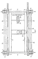
- the contour-cutting machine represented in the invention comprises a base frame 1 provided at its four corners with four vertical columns 2. These columns are interconnected at their tops by longitudinal beams 3 and cross-beams 4. It is to be observed that either beams 3 or beams 4 or both types of beam may be omitted, if desired, provided that the drives to be mentioned hereinafter are mounted at some other point.
- a beam section 5 has been mounted along each column.
- This section has the form of a channel bar, the open side of the bar being turned inwards.
- the beam section 5 can be moved along a column by means of a guide member 6 whose vertical movements are controlled with the aid of a counterweight 8 hanging in balanced suspension from a cable passed over rollers 7.
- the vertical displacement of each guide member 6 is effected by means of a screwed-spindle and nut construction - not further specified - which has been fitted within or alongside each column 2.
- the vertical drive may be provided either by separate, synchronously operating motors for each of the columns 1 or through a mechanical link-up of the drives for each of the four columns. Again, no further details are given, because the system has already been described in the aforementioned European patent application no. EP 0097.992.
- each support 10 for the filaments has been inserted on both sides of the apparatus.
- a rocker arm 11 with tension bars 12 has been attached to each support 10.
- These tension bars are connected on both sides by filaments with springs, which are not represented in detail, having also been described in the aforementioned European patent application.
- a shaft for the supply of cooling air, not represented either, may also be present.
- Each support 10 extends on both sides beyond two columns, and is provided with a retaining nut 13 which engages with a threaded rod 14.
- each threaded rod 14 is jou rnalled on a beam section 5.
- One of these beam sections is invariably provided with a right-angled transmission 15 through which a splined shaft 16 extends.
- each of these two shafts may itself be provided with a mutually synchronous motor, placed for instance on the associated beam section.
- An electric motor 22 is connected through shafts to the columns in order to effect the vertical displacement of the sections 5 with guide members 6 along each column. Obviously, it is again possible to use separate, synchronously operating motors for each of the columns.
- the support 10 is invariably journalled in two beam sections 5 in such a way as to be horizontally movable.
- a number of bearing rollers 23 have been mounted against which the support rests by means of guiding tracks 24.
- the two supports 10 are only connected together by means of the filaments. In consequence, there are no fixed cross connections between these two supports, so that besides the filaments themselves either clamping members or adjacent blocks of starting material may be present in the passage of the plastic material to be cut which have no adverse effect whatever on the proper operation of the contour- . cutting apparatus.
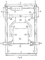
- a block of starting material 30 rests on a work table 31, whilst dashed lines represent a supply conveyor 32 and a discharge conveyor 33.
- an effective operation is attained by the introduction of a couple of guiding tracks 40 and 41 in the upper part of the apparatus.
- Each of these guiding tracks may support a travelling crab 42 and 43, respectively, intended to exert pressure on a block of starting material by means of a suspended arm 44 and clamping plate 45.
- a work table 31 and supply and discharge conveyors 32 and 33 so that the filaments of the cutting device themselves can be displaced to a position underneath the block of starting material.
- a block of starting material can both be supplied and, after cutting of the separate products, be discharged without experiencing any hindrance from the filaments.
- Figures 5 and 6 show other possible ways of clamping designed to hold the block and the wholly or partially finished products in position during the cutting.
- the clamping means depicted in figure 5 consists of a bar 46 which presses the block onto the work table 31.
- the clamping means incorporated in the upper part of the apparatus comprise guiding tracks 47 and 48 which support one or more travelling crabs 49, whilst an arm block 50 suspended from a beam 51 is provided with two arms 52 which grip the long sides of the block of starting material or the wholly or partially finished products by means of clamping plates 53.
- This clamping system which somewhat resembles the one shown in figures 1 and 3, is likewise capable of performing a horizontal movement over the roller conveyor, the cutting device and the conveyor beyond the cutting device, whilst this clamping member can also make a slight vertical movement in order to lift either the block of starting material or the finished products.
Landscapes
- Life Sciences & Earth Sciences (AREA)
- Forests & Forestry (AREA)
- Engineering & Computer Science (AREA)
- Mechanical Engineering (AREA)
- Treatment Of Fiber Materials (AREA)
- Perforating, Stamping-Out Or Severing By Means Other Than Cutting (AREA)
- Processing Of Stones Or Stones Resemblance Materials (AREA)
Claims (7)
Priority Applications (1)
| Application Number | Priority Date | Filing Date | Title |
|---|---|---|---|
| AT86200281T ATE52055T1 (de) | 1985-02-25 | 1986-02-24 | Verfahren und vorrichtung zum formschneiden. |
Applications Claiming Priority (2)
| Application Number | Priority Date | Filing Date | Title |
|---|---|---|---|
| NL8500525A NL8500525A (nl) | 1985-02-25 | 1985-02-25 | Werkwijze en inrichting voor het contoursnijden. |
| NL8500525 | 1985-02-25 |
Publications (2)
| Publication Number | Publication Date |
|---|---|
| EP0195470A1 EP0195470A1 (de) | 1986-09-24 |
| EP0195470B1 true EP0195470B1 (de) | 1990-04-18 |
Family
ID=19845585
Family Applications (1)
| Application Number | Title | Priority Date | Filing Date |
|---|---|---|---|
| EP86200281A Expired - Lifetime EP0195470B1 (de) | 1985-02-25 | 1986-02-24 | Verfahren und Vorrichtung zum Formschneiden |
Country Status (4)
| Country | Link |
|---|---|
| EP (1) | EP0195470B1 (de) |
| AT (1) | ATE52055T1 (de) |
| DE (1) | DE3670466D1 (de) |
| NL (1) | NL8500525A (de) |
Families Citing this family (3)
| Publication number | Priority date | Publication date | Assignee | Title |
|---|---|---|---|---|
| FR2787376B1 (fr) * | 1998-12-22 | 2001-03-09 | Esox | Procede et installation de decoupe de pieces de forme quelconque |
| DE102008052584B4 (de) * | 2007-10-22 | 2016-05-19 | Albrecht Bäumer GmbH & Co.KG | Seitenhalter für Maschinen |
| CN114734508B (zh) * | 2022-06-13 | 2022-08-23 | 济南正恒聚氨酯材料有限公司 | 一种用于聚氨酯硬泡沫加工的切割机 |
Family Cites Families (6)
| Publication number | Priority date | Publication date | Assignee | Title |
|---|---|---|---|---|
| US3350968A (en) * | 1963-10-31 | 1967-11-07 | Baldwin Ehret Hill Inc | Cutting apparatus |
| DE2156687A1 (de) * | 1971-11-15 | 1973-05-24 | Walter Pottmann | Schneidmaschine fuer koerper aus schaumstoff |
| NL7208952A (en) * | 1972-06-28 | 1974-01-02 | Insulating panels/shells - by cutting through block of foamed plastic mate-rial with heated wire | |
| US4175455A (en) * | 1978-03-22 | 1979-11-27 | Mcneil Corporation | Travelling cut-off saw |
| EP0035852A3 (de) * | 1980-02-27 | 1981-09-23 | J. MacA. King & Co., Limited | Formschneidevorrichtungen |
| NL8202437A (nl) * | 1982-06-16 | 1984-01-16 | Dijk Bv Gebr Van | Werkwijze en inrichting voor het contoursnijden van kunststof produkten, en verbeterde contourgesneden produkten. |
-
1985
- 1985-02-25 NL NL8500525A patent/NL8500525A/nl not_active Application Discontinuation
-
1986
- 1986-02-24 AT AT86200281T patent/ATE52055T1/de not_active IP Right Cessation
- 1986-02-24 EP EP86200281A patent/EP0195470B1/de not_active Expired - Lifetime
- 1986-02-24 DE DE8686200281T patent/DE3670466D1/de not_active Expired - Fee Related
Also Published As
| Publication number | Publication date |
|---|---|
| NL8500525A (nl) | 1986-09-16 |
| ATE52055T1 (de) | 1990-05-15 |
| EP0195470A1 (de) | 1986-09-24 |
| DE3670466D1 (de) | 1990-05-23 |
Similar Documents
| Publication | Publication Date | Title |
|---|---|---|
| KR960006832B1 (ko) | 절단기에서의 공작물 이송방법 및 장치 | |
| US5044488A (en) | Article transfer apparatus | |
| EP1402971B1 (de) | Vorrichtung zum Zuführen von Werkstücken für eine Presse | |
| CN215698420U (zh) | 一种板材加工用连续剪板机 | |
| EP0097992B1 (de) | Verfahren und Vorrichtung zum Konturschneiden von Kunststoffprodukten | |
| US4834275A (en) | Apparatus for acting on glass sheets | |
| EP0195470A1 (de) | Verfahren und Vorrichtung zum Formschneiden | |
| CN108326977B (zh) | 一种板料加工设备的进料装置 | |
| CA1090067A (en) | Method and apparatus for splitting a body of a butchered animal into two halves along the spine | |
| US2560843A (en) | Tile cutting machine | |
| US4296662A (en) | Method of and apparatus for cutting sheets of glass | |
| CA1260822A (en) | Device for the automatic and continuous correction of the centres of oscillation in a pendulant frame for the cutting of marbles, granites and hard stones | |
| GB2025304A (en) | Cutting a block of material such as clay | |
| KR100318062B1 (ko) | 금속절삭용 밴드 소오잉 머신 | |
| GB2122072A (en) | Cheese cutting apparatus | |
| GB1598940A (en) | Method and apparatus for the grouping of green bricks into a setting formation | |
| CN218802640U (zh) | 冲孔切边机 | |
| CN220806250U (zh) | 一种全自动生产的法兰机 | |
| SU1660872A1 (ru) | Устройство дл получени изделий из листового материала | |
| EP1574484B1 (de) | Verfahren zum Schneiden und Trennen von Glasscheiben, und vertikale Vorrichtung zur Herstellung dieses Verfahrens | |
| JPH1190561A (ja) | トランスファフィーダ | |
| SU1544310A1 (ru) | Устройство дл резки блоков сыра | |
| SU960011A1 (ru) | Агрегатный станок дл изготовлени пилопродукции | |
| SU884979A1 (ru) | Устройство дл резки изделий | |
| SU967630A1 (ru) | Устройство дл отделени верхнего листа от стопы и подачи его к обрабатывающей машине |
Legal Events
| Date | Code | Title | Description |
|---|---|---|---|
| PUAI | Public reference made under article 153(3) epc to a published international application that has entered the european phase |
Free format text: ORIGINAL CODE: 0009012 |
|
| AK | Designated contracting states |
Kind code of ref document: A1 Designated state(s): AT BE CH DE FR GB IT LI LU NL SE |
|
| 17P | Request for examination filed |
Effective date: 19870223 |
|
| 17Q | First examination report despatched |
Effective date: 19880516 |
|
| GRAA | (expected) grant |
Free format text: ORIGINAL CODE: 0009210 |
|
| AK | Designated contracting states |
Kind code of ref document: B1 Designated state(s): AT BE CH DE FR GB IT LI LU NL SE |
|
| REF | Corresponds to: |
Ref document number: 52055 Country of ref document: AT Date of ref document: 19900515 Kind code of ref document: T |
|
| REF | Corresponds to: |
Ref document number: 3670466 Country of ref document: DE Date of ref document: 19900523 |
|
| ITF | It: translation for a ep patent filed | ||
| ET | Fr: translation filed | ||
| PLBI | Opposition filed |
Free format text: ORIGINAL CODE: 0009260 |
|
| ITTA | It: last paid annual fee | ||
| 26 | Opposition filed |
Opponent name: SYNPRODO B.V., Effective date: 19910117 |
|
| NLR1 | Nl: opposition has been filed with the epo |
Opponent name: SYNPRODO B.V. |
|
| PLBM | Termination of opposition procedure: date of legal effect published |
Free format text: ORIGINAL CODE: 0009276 |
|
| STAA | Information on the status of an ep patent application or granted ep patent |
Free format text: STATUS: OPPOSITION PROCEDURE CLOSED |
|
| 27C | Opposition proceedings terminated |
Effective date: 19921030 |
|
| EPTA | Lu: last paid annual fee | ||
| NLR2 | Nl: decision of opposition | ||
| EAL | Se: european patent in force in sweden |
Ref document number: 86200281.3 |
|
| PGFP | Annual fee paid to national office [announced via postgrant information from national office to epo] |
Ref country code: GB Payment date: 19990225 Year of fee payment: 14 |
|
| PGFP | Annual fee paid to national office [announced via postgrant information from national office to epo] |
Ref country code: AT Payment date: 19990226 Year of fee payment: 14 |
|
| PGFP | Annual fee paid to national office [announced via postgrant information from national office to epo] |
Ref country code: SE Payment date: 19990301 Year of fee payment: 14 |
|
| PGFP | Annual fee paid to national office [announced via postgrant information from national office to epo] |
Ref country code: LU Payment date: 19990310 Year of fee payment: 14 Ref country code: CH Payment date: 19990310 Year of fee payment: 14 |
|
| PG25 | Lapsed in a contracting state [announced via postgrant information from national office to epo] |
Ref country code: LU Free format text: LAPSE BECAUSE OF NON-PAYMENT OF DUE FEES Effective date: 20000224 Ref country code: GB Free format text: LAPSE BECAUSE OF NON-PAYMENT OF DUE FEES Effective date: 20000224 Ref country code: AT Free format text: LAPSE BECAUSE OF NON-PAYMENT OF DUE FEES Effective date: 20000224 |
|
| PG25 | Lapsed in a contracting state [announced via postgrant information from national office to epo] |
Ref country code: SE Free format text: LAPSE BECAUSE OF NON-PAYMENT OF DUE FEES Effective date: 20000225 |
|
| PG25 | Lapsed in a contracting state [announced via postgrant information from national office to epo] |
Ref country code: LI Free format text: LAPSE BECAUSE OF NON-PAYMENT OF DUE FEES Effective date: 20000229 Ref country code: CH Free format text: LAPSE BECAUSE OF NON-PAYMENT OF DUE FEES Effective date: 20000229 |
|
| EUG | Se: european patent has lapsed |
Ref document number: 86200281.3 |
|
| GBPC | Gb: european patent ceased through non-payment of renewal fee |
Effective date: 20000224 |
|
| REG | Reference to a national code |
Ref country code: CH Ref legal event code: PL |
|
| PGFP | Annual fee paid to national office [announced via postgrant information from national office to epo] |
Ref country code: FR Payment date: 20020312 Year of fee payment: 17 |
|
| PGFP | Annual fee paid to national office [announced via postgrant information from national office to epo] |
Ref country code: DE Payment date: 20020313 Year of fee payment: 17 |
|
| PGFP | Annual fee paid to national office [announced via postgrant information from national office to epo] |
Ref country code: BE Payment date: 20020418 Year of fee payment: 17 |
|
| PG25 | Lapsed in a contracting state [announced via postgrant information from national office to epo] |
Ref country code: BE Free format text: LAPSE BECAUSE OF NON-PAYMENT OF DUE FEES Effective date: 20030228 |
|
| PG25 | Lapsed in a contracting state [announced via postgrant information from national office to epo] |
Ref country code: DE Free format text: LAPSE BECAUSE OF NON-PAYMENT OF DUE FEES Effective date: 20030902 |
|
| PG25 | Lapsed in a contracting state [announced via postgrant information from national office to epo] |
Ref country code: FR Free format text: LAPSE BECAUSE OF NON-PAYMENT OF DUE FEES Effective date: 20031031 |
|
| REG | Reference to a national code |
Ref country code: FR Ref legal event code: ST |
|
| PG25 | Lapsed in a contracting state [announced via postgrant information from national office to epo] |
Ref country code: IT Free format text: LAPSE BECAUSE OF NON-PAYMENT OF DUE FEES;WARNING: LAPSES OF ITALIAN PATENTS WITH EFFECTIVE DATE BEFORE 2007 MAY HAVE OCCURRED AT ANY TIME BEFORE 2007. THE CORRECT EFFECTIVE DATE MAY BE DIFFERENT FROM THE ONE RECORDED. Effective date: 20050224 |
|
| PGFP | Annual fee paid to national office [announced via postgrant information from national office to epo] |
Ref country code: NL Payment date: 20050228 Year of fee payment: 20 |
|
| PG25 | Lapsed in a contracting state [announced via postgrant information from national office to epo] |
Ref country code: NL Free format text: LAPSE BECAUSE OF EXPIRATION OF PROTECTION Effective date: 20060224 |
|
| NLV7 | Nl: ceased due to reaching the maximum lifetime of a patent |
Effective date: 20060224 |