EP0195506B1 - Sceau de sûreté - Google Patents
Sceau de sûreté Download PDFInfo
- Publication number
- EP0195506B1 EP0195506B1 EP86300840A EP86300840A EP0195506B1 EP 0195506 B1 EP0195506 B1 EP 0195506B1 EP 86300840 A EP86300840 A EP 86300840A EP 86300840 A EP86300840 A EP 86300840A EP 0195506 B1 EP0195506 B1 EP 0195506B1
- Authority
- EP
- European Patent Office
- Prior art keywords
- strip
- locking
- holes
- security seal
- indicating member
- Prior art date
- Legal status (The legal status is an assumption and is not a legal conclusion. Google has not performed a legal analysis and makes no representation as to the accuracy of the status listed.)
- Expired
Links
- 239000004033 plastic Substances 0.000 claims description 24
- 229920003023 plastic Polymers 0.000 claims description 24
- 239000002184 metal Substances 0.000 claims description 12
- 229910052751 metal Inorganic materials 0.000 claims description 12
- 239000003086 colorant Substances 0.000 claims description 3
- 238000003780 insertion Methods 0.000 claims description 3
- 230000037431 insertion Effects 0.000 claims description 3
- 239000012528 membrane Substances 0.000 claims description 3
- 230000000694 effects Effects 0.000 claims description 2
- 239000000463 material Substances 0.000 description 6
- 238000012360 testing method Methods 0.000 description 5
- 229910000831 Steel Inorganic materials 0.000 description 4
- 239000010959 steel Substances 0.000 description 4
- 239000002775 capsule Substances 0.000 description 3
- 238000010276 construction Methods 0.000 description 3
- 238000013461 design Methods 0.000 description 3
- 238000000034 method Methods 0.000 description 3
- 229910000639 Spring steel Inorganic materials 0.000 description 2
- 238000004519 manufacturing process Methods 0.000 description 2
- 230000000007 visual effect Effects 0.000 description 2
- 241000251468 Actinopterygii Species 0.000 description 1
- 229910001369 Brass Inorganic materials 0.000 description 1
- RYGMFSIKBFXOCR-UHFFFAOYSA-N Copper Chemical compound [Cu] RYGMFSIKBFXOCR-UHFFFAOYSA-N 0.000 description 1
- AYFVYJQAPQTCCC-GBXIJSLDSA-N L-threonine Chemical compound C[C@@H](O)[C@H](N)C(O)=O AYFVYJQAPQTCCC-GBXIJSLDSA-N 0.000 description 1
- 230000002411 adverse Effects 0.000 description 1
- 239000004411 aluminium Substances 0.000 description 1
- 229910052782 aluminium Inorganic materials 0.000 description 1
- XAGFODPZIPBFFR-UHFFFAOYSA-N aluminium Chemical compound [Al] XAGFODPZIPBFFR-UHFFFAOYSA-N 0.000 description 1
- 238000005452 bending Methods 0.000 description 1
- 239000010951 brass Substances 0.000 description 1
- 150000001875 compounds Chemical class 0.000 description 1
- 239000010949 copper Substances 0.000 description 1
- 229910052802 copper Inorganic materials 0.000 description 1
- 230000001419 dependent effect Effects 0.000 description 1
- 239000003292 glue Substances 0.000 description 1
- JEIPFZHSYJVQDO-UHFFFAOYSA-N iron(III) oxide Inorganic materials O=[Fe]O[Fe]=O JEIPFZHSYJVQDO-UHFFFAOYSA-N 0.000 description 1
- 238000012986 modification Methods 0.000 description 1
- 230000004048 modification Effects 0.000 description 1
- 239000000523 sample Substances 0.000 description 1
- 238000007789 sealing Methods 0.000 description 1
Images

Classifications
-
- G—PHYSICS
- G09—EDUCATION; CRYPTOGRAPHY; DISPLAY; ADVERTISING; SEALS
- G09F—DISPLAYING; ADVERTISING; SIGNS; LABELS OR NAME-PLATES; SEALS
- G09F3/00—Labels, tag tickets, or similar identification or indication means; Seals; Postage or like stamps
- G09F3/02—Forms or constructions
- G09F3/03—Forms or constructions of security seals
- G09F3/0305—Forms or constructions of security seals characterised by the type of seal used
-
- Y—GENERAL TAGGING OF NEW TECHNOLOGICAL DEVELOPMENTS; GENERAL TAGGING OF CROSS-SECTIONAL TECHNOLOGIES SPANNING OVER SEVERAL SECTIONS OF THE IPC; TECHNICAL SUBJECTS COVERED BY FORMER USPC CROSS-REFERENCE ART COLLECTIONS [XRACs] AND DIGESTS
- Y10—TECHNICAL SUBJECTS COVERED BY FORMER USPC
- Y10T—TECHNICAL SUBJECTS COVERED BY FORMER US CLASSIFICATION
- Y10T292/00—Closure fasteners
- Y10T292/48—Seals
- Y10T292/503—Split-ring catch, shackle operated
-
- Y—GENERAL TAGGING OF NEW TECHNOLOGICAL DEVELOPMENTS; GENERAL TAGGING OF CROSS-SECTIONAL TECHNOLOGIES SPANNING OVER SEVERAL SECTIONS OF THE IPC; TECHNICAL SUBJECTS COVERED BY FORMER USPC CROSS-REFERENCE ART COLLECTIONS [XRACs] AND DIGESTS
- Y10—TECHNICAL SUBJECTS COVERED BY FORMER USPC
- Y10T—TECHNICAL SUBJECTS COVERED BY FORMER US CLASSIFICATION
- Y10T292/00—Closure fasteners
- Y10T292/513—Shackles
- Y10T292/534—Seal-rupturing devices
Definitions
- This invention relates to a security seal.
- Such seals are used to maintain the security of goods in transit, in that any attempt to open the seal by unauthorised personnel should leave visible evidence of tampering.
- the invention is particularly concerned with seals of the kind known as strip seals see for example US-A-2343564 and US-A-4093287. These comprise a flexible strip, one end of which is fixed inside a locking box or chamber. In use, the free end of the strip is bent back and inserted through an entry slot in the locking box for non-detachable locking therein.
- Strip seals can be subdivided into two main categories: ball strip seals and flat strip seals, both of these terms referring to the shape of the locking box.
- the portion of the first end of the strip inside the ball-shaped locking box is bent back upon itself to form a channel for receiving the free end of the strip.
- holes in this channel section and in the free end of the strip are in register and locking is effected by one or more, usually two, spring steel circlips (circular clips) which pass through the holes.
- the circlips have free ends which, in the unlocked position, are resiliently spaced apart by the outer faces of the channel section backward (with reference to the direction of insertion of the free end of the strip) of the holes in the channel.
- the leading edge thereof urges the circlips forward until, when all the holes are in register, the free ends of the circlips spring into the holes to effect locking.
- the dimensions of the holes are chosen so that there is a certain degree of free play of the free end of the strip in the locked position. This feature is utilised to provide visible evidence that the seal is locked. Opposite the entry slot in the locking box thre is an exit slot and, in the locked position, it is possible to push the free end of the strip forward so that it partly protrudes from the exit slot, showing that the seal is locked.
- the strip is marked with identification letters and/ or numbers to make each seal individually identifiable.
- the locking box in ball seals usually comprises a ball housing of two substantially hemispherical parts that are swaged together creating a seam of varying strength of vulnerability. In some designs, a separate additional piece of material is crimped over the overlapping portions.
- Various illicit methods of opening the locking box and then re-sealing it have been developed. For example, the box may be cut open with a very fine saw, thereby giving access to the interior so that the circlips can be opened. The mechanism can then be re-set and the locking box re-sealed with glue. The end result can be very difficult to detect, especially under operational conditions.
- An object of the present invention is to overcome the problems outlined above in connection with ball seals, whilst preferably maintaining the superior strength of the ball seal in comparison with flat seals.
- the invention is particularly useful in connection with ball strip seals, it also has general applicability to strip seals.
- the present invention provides a security seal comprising a flexible strip, a locking box attached to a first end of the strip, and a free, second end of the strip being insertable through an entry slot in the locking box for non-detachable locking therein, characterised in that an indicating member is arranged inside the box adjacent a rupturable wall thereof so that, when locking of the free end of the strip is effected, the indicating member is caused to rupture the wall and thereby provide visible evidence of locking.
- the locking box preferably comprises a plastics inner lining substantially covered by an outer metal skin, such that there is a portion of one end wall having uncovered plastics material and having therein an area of weakness which is rupturable by the indicating member.
- the locking box is substantially_cylindrical with rounded edges
- the outer metal skin covers the sides and is rolled over at both ends of the box leaving an uncovered plastics portion at the centre of each end wall, one end wall having an entry slot for the strip and the opposite end wall having an area of weakness rupturable by the indicating member.
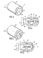
- the locking box is substantially cylindrical with rounded corners and comprises an inner, hollow plastics capsule 1 (shown in cut-away portion of Figure 1) and an outer seamless metal skin 2.
- the metal skin covers the sides and is rolled over or spun at both ends of the box, leaving an exposed central section of a plastics end wall 3 with an entry slot 4, and an exposed central section of a plastics end wall 5 at the opposite end of the locking box.
- the inner plastics capsule 1 is made in two halves separated by a longitudinal joint 6.
- the flexible strip 7 is of metal and the first end, fixed inside the locking box, is bent back upon itself as shown in Figure 2.
- Profiled configurations 8 are formed in this bent back portion and engage with corresponding configurations (not shown) inside the plastics capsule, to locate and fix the bent back portion of the strip inside the locking box.
- the bent back portion defines a longitudinally extending channel into which the free end of the strip can be inserted. Entry of the free end of the strip into this channel is assisted by a shaped flap 9 at the tip of the bent back portion, the flap being external of the locking box and the bent back portion being substantially within the locking box and protruding from the entry slot 4.
- Locking of the seal is achieved by a modification of the ball seal locking mechanism.
- a pair of circular holes 10 in register with each other is arranged in the folded back portion. Forward of this pair of holes there is a longitudinally extending cut-out section 11.
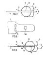
- a pair of spring steel circlips 12 passes through the cut-out 11 and, in the unlocked position, the ends of the circlips are resiliently spaced apart by the outer faces of the bent back portion, as shown in Figures 4 and 7.
- the free end of the flexible strip has a circular hole 10A of the same dimensions as the pair of holes 10. In order to achieve locking, the free end of the strip is inserted into the entry slot 4 of the locking box, and into the channel defined by the folded back portion of the fixed end of the strip.
- the leading edge of the free end passes through the channel, past the pair of holes 10, until it reaches the cutout 11, whereupon it abuts against the circlips 12.
- Further insertion into the locking box causes the leading edge of the free end of the strip to urge the circlips forwards in the direction of the arrows in Figures 6 and 9.
- the opened ends of the circlips then pass over the outer faces of the bent back portion towards the pair of holes 10, being guided by converging ribs 12 on the outer faces of the bent back portion.
- the opened ends of the circlips reach the pair of holes 10 they spring into the holes and the circlips are thus resiliently closed.
- the indicating member has a base portion and a tip portion, the tip portion being pointed and, in the unlocked position ( Figure 4), adjacent the inside of a thin section 14 (shown by broken lines in Figure 3) of the wall 5.
- the base portion of the indicating member 13 has a longitudinally extending cut-out so that it can be positioned astride the bent back portion and abutting the ends of the circlips 12 ( Figure 7).
- the tip portion of the indicating member pierces the weakened section 14 of the end wall 5 and protrudes from the end wall as shown in Figures 5 and 6.
- the indicating member 13 is of plastics material, and is of a colour which contrasts with the colour of the end wall 5, so that the protruding tip is readily visible.
- the holes 10 in the bent back portion and the hole 10A in the free end of the strip are of relatively small dimensions compared with conventional ball seals, so that there is only a relatively small amount of longitudinal free play of the free end of the strip in the locked position.
- the strip When the seal is to be opened by authorised personnel, the strip can simply be cut. However, this requires a secondary cutting implement or tool, whereas in a preferred embodiment the strip has a transverse line of weakness to facilitate manual breakage. More preferably, the flexible strip has two such lines of weakness in the form of perforations 15 arranged near the two ends, so that the two lines of perforations are outside the locking box and are in register in the locked position, thereby providing an additional indication of locking.
- the perforations 15 may, for example, consist of a single circular hole (as shown in Figure 1) or a pair of elongated holes (as shown in the other Figures).
- the seal which has been described above has a number of advantageous features in comparison to conventional ball seals.
- the indicating member of contrasting colour when it has burst through the end wall of the locking box, provides a readily visible and tactile indication of locking. This indication is not dependent upon manipulation of the free end of the strip as in conventional ball seals. It should be noted that such manipulation can only be done manually, and becomes virtually impossible under certain operational conditions, e.g. when the seal is on a container which is out of reach of an inspector. In such cases, visual examination is the only viable means of checking whether the seal is properly sealed.
- the vulnerability of the locking box itself to unauthorised interference has been greatly reduced by means of the two part plastics and metal construction.
- the outer steel skin is seamless and, in manufacture, is rolled over or spun around the ends of the plastics capsuleto leave the exposed central sections of the plastics end walls.
- the contrasting strengths of the materials used, hard steel over relatively soft plastics material compounds the difficulty of deforming the rolled- over ends of the metal skin without damaging beyond repair the ends of the plastics chamber. In fact, unsealing the metal housing by attempting to bend back the turned-in metal end that curves over the contours of the plastic chamber is virtually impossible even under laboratory conditions.
- the metal skin is rolled over at the ends in a totally smooth manner, which greatly increases its inherent strength.
- the outer metal skin of the locking box and the flexible strip will generally be of rust-resistant steel, but other materials, such as aluminium, brass, copper and painted steel, are also possible.
- the strip will be marked with identification letters and numbers.
- the plastics chamber can be made of varying colours, which will contrast with the colour of the indicating member which emerges on locking. Such colours can be used as the basis of a secure colour identification system, since the colour of the indicating member only becomes known when the seal has been locked.
Landscapes
- Engineering & Computer Science (AREA)
- Computer Security & Cryptography (AREA)
- Physics & Mathematics (AREA)
- General Physics & Mathematics (AREA)
- Theoretical Computer Science (AREA)
- Closures For Containers (AREA)
- Materials For Medical Uses (AREA)
- Cartons (AREA)
Claims (9)
Priority Applications (1)
| Application Number | Priority Date | Filing Date | Title |
|---|---|---|---|
| AT86300840T ATE47924T1 (de) | 1985-03-11 | 1986-02-07 | Sicherheitsplombe. |
Applications Claiming Priority (2)
| Application Number | Priority Date | Filing Date | Title |
|---|---|---|---|
| GB858506229A GB8506229D0 (en) | 1985-03-11 | 1985-03-11 | Security seal |
| GB8506229 | 1985-03-11 |
Publications (2)
| Publication Number | Publication Date |
|---|---|
| EP0195506A1 EP0195506A1 (fr) | 1986-09-24 |
| EP0195506B1 true EP0195506B1 (fr) | 1989-11-08 |
Family
ID=10575792
Family Applications (1)
| Application Number | Title | Priority Date | Filing Date |
|---|---|---|---|
| EP86300840A Expired EP0195506B1 (fr) | 1985-03-11 | 1986-02-07 | Sceau de sûreté |
Country Status (11)
| Country | Link |
|---|---|
| US (1) | US4690444A (fr) |
| EP (1) | EP0195506B1 (fr) |
| AT (1) | ATE47924T1 (fr) |
| AU (1) | AU577752B2 (fr) |
| BR (1) | BR8601020A (fr) |
| CA (1) | CA1278670C (fr) |
| DE (1) | DE3666888D1 (fr) |
| GB (1) | GB8506229D0 (fr) |
| IE (1) | IE57214B1 (fr) |
| NZ (1) | NZ215147A (fr) |
| ZA (1) | ZA861181B (fr) |
Families Citing this family (6)
| Publication number | Priority date | Publication date | Assignee | Title |
|---|---|---|---|---|
| FR2630772B1 (fr) * | 1988-04-29 | 1991-07-26 | Colchen Fabrice | Scelle de haute securite, en particulier pour porte de wagon ou de conteneur |
| GB2219554B (en) * | 1988-06-02 | 1992-03-25 | Deutsher Pty Ltd | Strap-type security seal |
| US4950007A (en) * | 1988-06-22 | 1990-08-21 | E. J. Brooks Company | Ball seal |
| US5768760A (en) * | 1995-10-31 | 1998-06-23 | Nynex Science & Technology, Inc. | System and method for automatically processing coin collection boxes |
| DE60220638T2 (de) * | 2002-03-27 | 2008-02-14 | Itw Ltd., Swansea | Sicherheitssiegel |
| US7325281B1 (en) | 2006-07-25 | 2008-02-05 | George Lee Willems | Security strap |
Family Cites Families (17)
| Publication number | Priority date | Publication date | Assignee | Title |
|---|---|---|---|---|
| US1320832A (en) * | 1919-11-04 | Setts | ||
| US641785A (en) * | 1899-04-17 | 1900-01-23 | Rockwell M Maccormac | Car-seal. |
| CH62569A (de) * | 1912-10-07 | 1913-12-01 | Th Fluri | Knöpfvorrichtung |
| US1112123A (en) * | 1914-05-20 | 1914-09-29 | John C Rasmussen | Car-seal. |
| US1433793A (en) * | 1921-03-08 | 1922-10-31 | Carr Fastener Co Ltd | Fastener |
| US1496885A (en) * | 1921-07-20 | 1924-06-10 | Russell S Jones | Seal |
| FR813487A (fr) * | 1936-10-06 | 1937-06-02 | Dispositif élastique d'assemblage, de fermeture, de réunion ou de liaison | |
| US2343564A (en) * | 1941-03-21 | 1944-03-07 | Ketchum Mfg Co Ltd | Seal |
| US2374898A (en) * | 1944-05-03 | 1945-05-01 | William D Rossiter | Cabinet locking means |
| GB621404A (en) * | 1946-10-14 | 1949-04-08 | Kurt Bieber | Improvements relating to snap fasteners |
| US2895199A (en) * | 1955-04-12 | 1959-07-21 | United Carr Fastener Corp | All plastic separable fastener of the press button type |
| US2869911A (en) * | 1955-05-31 | 1959-01-20 | Wallace J Dickey | Self-locking shackle seal |
| US4006471A (en) * | 1975-01-31 | 1977-02-01 | Detex Corporation | Emergency exit lock system for doors |
| US4093287A (en) * | 1977-02-22 | 1978-06-06 | Canter George G | Car seal |
| US4118057A (en) * | 1978-02-24 | 1978-10-03 | The United States Of America As Represented By The United States Department Of Energy | Reusable, tamper-indicating seal |
| US4295761A (en) * | 1979-12-10 | 1981-10-20 | Stratabolt Corporation | Post tensionable grouted anchor assembly |
| US4616953A (en) * | 1985-09-27 | 1986-10-14 | Daniel Gomes | Knock down pivot fastener |
-
1985
- 1985-03-11 GB GB858506229A patent/GB8506229D0/en active Pending
-
1986
- 1986-02-07 DE DE8686300840T patent/DE3666888D1/de not_active Expired
- 1986-02-07 AT AT86300840T patent/ATE47924T1/de not_active IP Right Cessation
- 1986-02-07 EP EP86300840A patent/EP0195506B1/fr not_active Expired
- 1986-02-11 IE IE386/86A patent/IE57214B1/en not_active IP Right Cessation
- 1986-02-13 NZ NZ215147A patent/NZ215147A/en unknown
- 1986-02-13 AU AU53451/86A patent/AU577752B2/en not_active Ceased
- 1986-02-14 CA CA000501902A patent/CA1278670C/fr not_active Expired - Lifetime
- 1986-02-17 ZA ZA861181A patent/ZA861181B/xx unknown
- 1986-02-26 US US06/833,020 patent/US4690444A/en not_active Expired - Lifetime
- 1986-03-10 BR BR8601020A patent/BR8601020A/pt not_active IP Right Cessation
Also Published As
| Publication number | Publication date |
|---|---|
| CA1278670C (fr) | 1991-01-08 |
| BR8601020A (pt) | 1986-11-18 |
| US4690444A (en) | 1987-09-01 |
| EP0195506A1 (fr) | 1986-09-24 |
| GB8506229D0 (en) | 1985-04-11 |
| ATE47924T1 (de) | 1989-11-15 |
| ZA861181B (en) | 1986-12-30 |
| AU5345186A (en) | 1986-09-18 |
| DE3666888D1 (en) | 1989-12-14 |
| IE57214B1 (en) | 1992-06-03 |
| NZ215147A (en) | 1987-06-30 |
| IE860386L (en) | 1986-09-25 |
| AU577752B2 (en) | 1988-09-29 |
Similar Documents
| Publication | Publication Date | Title |
|---|---|---|
| US4506415A (en) | Security seal and tag holder | |
| US5762386A (en) | Tamper resistant seal and method of sealing an object | |
| CA2538396C (fr) | Fermeture de securite | |
| US4512599A (en) | Security sealing system | |
| EP0195506B1 (fr) | Sceau de sûreté | |
| US4909552A (en) | Detector seal | |
| PL192060B1 (pl) | Plomba zabezpieczająca | |
| US20050230981A1 (en) | Padlock | |
| EP2225167B1 (fr) | Joint de sécurité unitarisé amélioré | |
| US4793644A (en) | Security seal with dye | |
| EP0310597B1 (fr) | Joint | |
| GB2051942A (en) | Manually closable safety seal | |
| US4775175A (en) | Security seal having a color coded tampering indicator | |
| EP2063733B1 (fr) | Dispositif d'inviolabilité | |
| US4353583A (en) | Seal of the padlock type | |
| GB2163392A (en) | Security seal | |
| US2771314A (en) | Wrap-around car seal | |
| US3441304A (en) | Shipping seal | |
| GB1594207A (en) | Security seals | |
| US2823943A (en) | Automatic wire lock seal | |
| EP2198415B1 (fr) | Indicateur d'effraction | |
| RU2181096C1 (ru) | Гибкое запорно-пломбировочное устройство | |
| EP0071459A2 (fr) | Dispositif de sécurité | |
| US569387A (en) | Seal-padlock | |
| WO1996005586A1 (fr) | Dispositif d'etancheite verrouillable |
Legal Events
| Date | Code | Title | Description |
|---|---|---|---|
| PUAI | Public reference made under article 153(3) epc to a published international application that has entered the european phase |
Free format text: ORIGINAL CODE: 0009012 |
|
| AK | Designated contracting states |
Kind code of ref document: A1 Designated state(s): AT BE CH DE FR GB IT LI LU NL SE |
|
| 17P | Request for examination filed |
Effective date: 19861021 |
|
| 17Q | First examination report despatched |
Effective date: 19881219 |
|
| RAP3 | Party data changed (applicant data changed or rights of an application transferred) |
Owner name: ENVOPAK GROUP LIMITED |
|
| GRAA | (expected) grant |
Free format text: ORIGINAL CODE: 0009210 |
|
| AK | Designated contracting states |
Kind code of ref document: B1 Designated state(s): AT BE CH DE FR GB IT LI LU NL SE |
|
| REF | Corresponds to: |
Ref document number: 47924 Country of ref document: AT Date of ref document: 19891115 Kind code of ref document: T |
|
| REF | Corresponds to: |
Ref document number: 3666888 Country of ref document: DE Date of ref document: 19891214 |
|
| ET | Fr: translation filed | ||
| ITF | It: translation for a ep patent filed | ||
| PLBE | No opposition filed within time limit |
Free format text: ORIGINAL CODE: 0009261 |
|
| STAA | Information on the status of an ep patent application or granted ep patent |
Free format text: STATUS: NO OPPOSITION FILED WITHIN TIME LIMIT |
|
| 26N | No opposition filed | ||
| ITTA | It: last paid annual fee | ||
| EPTA | Lu: last paid annual fee | ||
| EAL | Se: european patent in force in sweden |
Ref document number: 86300840.5 |
|
| PGFP | Annual fee paid to national office [announced via postgrant information from national office to epo] |
Ref country code: LU Payment date: 19971216 Year of fee payment: 13 |
|
| PGFP | Annual fee paid to national office [announced via postgrant information from national office to epo] |
Ref country code: FR Payment date: 19980210 Year of fee payment: 13 |
|
| PGFP | Annual fee paid to national office [announced via postgrant information from national office to epo] |
Ref country code: AT Payment date: 19980211 Year of fee payment: 13 |
|
| PGFP | Annual fee paid to national office [announced via postgrant information from national office to epo] |
Ref country code: DE Payment date: 19980213 Year of fee payment: 13 |
|
| PGFP | Annual fee paid to national office [announced via postgrant information from national office to epo] |
Ref country code: SE Payment date: 19980218 Year of fee payment: 13 |
|
| PGFP | Annual fee paid to national office [announced via postgrant information from national office to epo] |
Ref country code: CH Payment date: 19980223 Year of fee payment: 13 |
|
| PGFP | Annual fee paid to national office [announced via postgrant information from national office to epo] |
Ref country code: NL Payment date: 19980226 Year of fee payment: 13 |
|
| PGFP | Annual fee paid to national office [announced via postgrant information from national office to epo] |
Ref country code: BE Payment date: 19980417 Year of fee payment: 13 |
|
| PG25 | Lapsed in a contracting state [announced via postgrant information from national office to epo] |
Ref country code: LU Free format text: LAPSE BECAUSE OF NON-PAYMENT OF DUE FEES Effective date: 19990207 Ref country code: AT Free format text: LAPSE BECAUSE OF NON-PAYMENT OF DUE FEES Effective date: 19990207 |
|
| PG25 | Lapsed in a contracting state [announced via postgrant information from national office to epo] |
Ref country code: SE Free format text: LAPSE BECAUSE OF NON-PAYMENT OF DUE FEES Effective date: 19990208 |
|
| PG25 | Lapsed in a contracting state [announced via postgrant information from national office to epo] |
Ref country code: LI Free format text: LAPSE BECAUSE OF NON-PAYMENT OF DUE FEES Effective date: 19990228 Ref country code: CH Free format text: LAPSE BECAUSE OF NON-PAYMENT OF DUE FEES Effective date: 19990228 Ref country code: BE Free format text: LAPSE BECAUSE OF NON-PAYMENT OF DUE FEES Effective date: 19990228 |
|
| BERE | Be: lapsed |
Owner name: ENVOPAK GROUP LTD Effective date: 19990228 |
|
| PG25 | Lapsed in a contracting state [announced via postgrant information from national office to epo] |
Ref country code: NL Free format text: LAPSE BECAUSE OF NON-PAYMENT OF DUE FEES Effective date: 19990901 |
|
| REG | Reference to a national code |
Ref country code: CH Ref legal event code: PL |
|
| PG25 | Lapsed in a contracting state [announced via postgrant information from national office to epo] |
Ref country code: FR Free format text: LAPSE BECAUSE OF NON-PAYMENT OF DUE FEES Effective date: 19991029 |
|
| EUG | Se: european patent has lapsed |
Ref document number: 86300840.5 |
|
| PG25 | Lapsed in a contracting state [announced via postgrant information from national office to epo] |
Ref country code: DE Free format text: LAPSE BECAUSE OF NON-PAYMENT OF DUE FEES Effective date: 19991201 |
|
| REG | Reference to a national code |
Ref country code: FR Ref legal event code: ST |
|
| REG | Reference to a national code |
Ref country code: GB Ref legal event code: IF02 |
|
| REG | Reference to a national code |
Ref country code: GB Ref legal event code: 732E |
|
| PGFP | Annual fee paid to national office [announced via postgrant information from national office to epo] |
Ref country code: GB Payment date: 20050202 Year of fee payment: 20 |
|
| PG25 | Lapsed in a contracting state [announced via postgrant information from national office to epo] |
Ref country code: IT Free format text: LAPSE BECAUSE OF NON-PAYMENT OF DUE FEES;WARNING: LAPSES OF ITALIAN PATENTS WITH EFFECTIVE DATE BEFORE 2007 MAY HAVE OCCURRED AT ANY TIME BEFORE 2007. THE CORRECT EFFECTIVE DATE MAY BE DIFFERENT FROM THE ONE RECORDED. Effective date: 20050207 |
|
| PG25 | Lapsed in a contracting state [announced via postgrant information from national office to epo] |
Ref country code: GB Free format text: LAPSE BECAUSE OF EXPIRATION OF PROTECTION Effective date: 20060206 |
|
| REG | Reference to a national code |
Ref country code: GB Ref legal event code: PE20 |